BASIC ELECTRICAL FOR THE HVAC TECHNICIAN
Trace the Circuit You Just Built
Shop Project — Use your meter to prove what the circuit is doing.
In the previous lessons you built a simple circuit,
learned Ohm’s Law, and learned how to use a meter.
Now you are going to put those skills together.
Safety First
This was originally a supervised shop exercise using
the electrical training board.
Do not reproduce this exercise on household line voltage
as an unsupervised experiment.
Voltage measurements require an energized circuit.
Resistance measurements require the circuit to be
completely de-energized.
If you are following this material independently,
use an appropriate low-voltage training system unless
you have suitable electrical training, equipment and
safety procedures.
What You Will Do
By the end of this exercise you should be able to:
Measure voltage between specific points in a circuit.
Measure resistance with the circuit de-energized.
Compare readings with what you expect the circuit to do.
Explain why the readings change when SW1 opens or closes.
The Circuit You Are Testing
This is the same basic circuit you built in the earlier
shop project.
Source
→
Path
→
SW1
→
B1
→
Return to Source
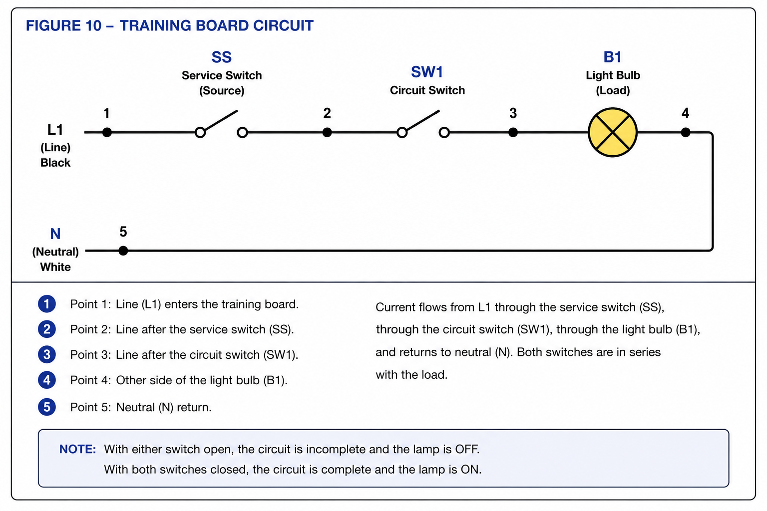
Basic training-board circuit used for the voltage and
resistance measurements in this exercise.
Using Your Meter
Voltage Measurements
Set the meter for the correct AC voltage range.
Voltage is measured between two points while the
circuit is energized.
Resistance Measurements
Turn the power OFF and disconnect the training board
before measuring resistance.
Set the meter to ohms (Ω).
Before every measurement, ask:
What should I expect the meter to read?
Then compare the actual reading with your expectation.
What You Should Have Learned
Voltage is measured between two points in an energized circuit.
Resistance is measured only on a de-energized circuit.
Opening and closing SW1 changes the electrical condition
of different points in the circuit.
Meter readings are useful only when you understand
what you expected to measure.
Original Course Sign-Off
In the original classroom version of this exercise,
the instructor reviewed the student’s measurements,
observed proper meter use, and asked the student to
explain the readings before signing off on the project.
If you are studying independently, you should be able
to explain why each measurement changes—or does not
change—when SW1 is opened or closed.