BASIC ELECTRICAL FOR THE HVAC TECHNICIAN
How to Use a Meter
Learn what your meter is telling you before you use
that reading to troubleshoot a circuit.
Your meter will probably be the most frequently used
electrical tool in your tool bag as a Heating and Air
Conditioning Technician. It is important that you understand
not only how to use the meter, but also what the reading
means.
Introduction to Meters
Anyone can put two meter leads on a circuit and read a
number from the display.
The important skill is knowing:
Where should I put the leads?
What reading should I expect?
What does the reading tell me about the circuit?
Remember:
Your meter should be the first tool out of your tool bag
and the last tool you put away.
Before you touch an electrical component, determine whether
voltage is present.
Before relying on a meter reading, make sure your meter is
working, the leads are in the correct terminals, and the meter
is set for the measurement you are trying to make.
Read the manual that came with your meter. Meters are not all
the same.
At a minimum, you should know how your meter measures AC voltage,
DC voltage, resistance,
current, and
continuity if that function
is provided.
Many HVAC meters also measure capacitance, frequency,
temperature and other values.
Having more functions does not make the meter useful unless
you understand what those measurements mean.
Before We Use the Meter
Before taking measurements, go back to the basic circuit
you learned earlier in this course.
→
Path
→
Switch
→
Load
→
Return to Source
The source supplies electrical potential.
The path provides a route for current.
The switch or control determines whether the circuit is complete.
The load uses electrical energy to do work.
The circuit must then have a path back to the other side
of the source.
When you troubleshoot a circuit with a meter, you are really
trying to answer one question:
What is happening at this point in the circuit?
The meter helps you answer that question.
Types of Meters
There are many brands and models of electrical meters, but
you will commonly encounter two basic types: analog and digital.
Analog Meters
Analog meters use a mechanical pointer moving across
a scale.
They were the standard electrical test instrument for
many years and are still useful for certain applications.
Because you have to interpret the position of the pointer
against a scale, you must select the correct range and
understand which scale you are reading.
Digital Meters
Digital meters have largely replaced analog meters
for HVAC service work.
Instead of reading a pointer, the measurement appears
on a digital display.
Many modern digital meters are auto-ranging.
Do not confuse auto-ranging with automatic function
selection.
You still need to tell the meter whether you are
measuring AC volts, DC volts, resistance, current,
or another quantity.
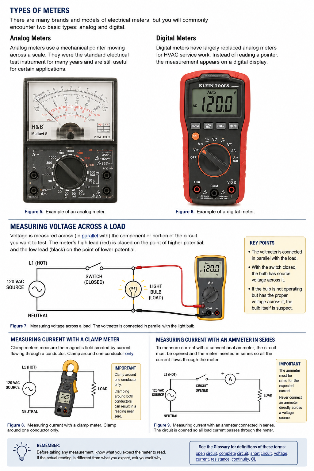
Meter types and common electrical measurement methods:
analog and digital meters, voltage measurement across a
load, clamp-meter current measurement, and current
measurement with an ammeter connected in series.
Prove Your Meter Before You Trust It
A meter reading is useful only if you know the meter is working.
Before relying on a voltage measurement, test the meter on a
known energized source when practical.
When verifying that a circuit is de-energized, use this sequence:
Known Live Source
→
Circuit Being Tested
→
Known Live Source
The first test proves the meter was working before your
measurement.
The second determines whether your circuit is energized.
The third proves that your meter and test leads were still
working after the measurement.
Do not assume that 0 volts automatically means
a circuit is safe.
Prove your meter.
Understanding Open Circuits
An open circuit does
not have a complete path for current.
Imagine this circuit:
There is electrical potential available on the source side
of the open switch, but current cannot complete the circuit
because the switch is open.
If you place one voltage-meter lead on each side of that
open switch, you should normally measure approximately
source voltage when the rest of the circuit is complete.
Open switch:
Approximately source voltage across the switch.
Now close the switch.
Both sides of a properly closed switch should be at almost
the same electrical potential.
Closed switch:
Approximately 0 volts across the switch.
These two measurements are among the most useful electrical
troubleshooting rules you will learn.
Understanding Complete Circuits
Now close the switch.
Current now has a
complete circuit.
If you place your voltage-meter leads across L1 and Neutral,
you should measure approximately source voltage.
If you place the meter across the working light bulb, you
should also measure approximately the voltage intended for
that load.
A working load must have the proper operating
voltage across it.
But be careful.
Measuring the correct voltage across a load does not prove
the load is good.
Suppose the filament inside the bulb is open.
Under the right circuit conditions, you may still measure
approximately source voltage across that failed bulb.
If the proper operating voltage is across a load, the load
should be operating, and it is not, the load becomes a strong
suspect.
That is evidence.
That is much better than guessing.
Measuring Voltage
Voltage is measured
between two points.
A voltmeter is therefore connected in parallel with the
component or part of the circuit being tested.
Voltage Measurement Procedure
- Inspect the meter and test leads.
-
Make sure the leads are plugged into the correct
meter terminals. - Turn the meter on.
- Select AC volts or DC volts as appropriate.
- Select the proper range if the meter is not auto-ranging.
-
Determine exactly which two points in the circuit
you need to measure. - Place one probe on each test point.
-
Keep your fingers behind the probe guards and away
from exposed conductive surfaces. - Allow the reading to stabilize.
Do not just put your probes somewhere in the circuit and
see what number appears.
Before touching the circuit, ask yourself:
What reading should I expect?
Using Voltage Across a Switch
Switch Open
If the rest of the circuit is complete, you should
normally measure approximately source voltage
across the open switch.
Switch Closed
You should normally measure approximately 0 volts
across a properly closed switch.
Do not simply memorize those readings.
Understand why you get them.
The same idea applies later to thermostats, pressure switches,
safety controls, relay contacts and contactors.
Using Voltage Across a Load
Put your meter across the load.
If a light bulb designed for 120 volts has approximately
120 volts across it, the bulb has the voltage it needs
to operate.
If it lights, that is normal.
If approximately 120 volts is across the bulb and it does
not light, the bulb itself becomes suspect.
You did not guess that the bulb was bad.
You proved that the circuit was supplying the bulb
with the voltage it needed.
Measuring Current
Current is measured in
amperes, or amps.
There are two common ways to measure current:
Clamp Meter
A clamp meter measures the magnetic field created by
current flowing through a conductor.
For most HVAC line-voltage work, this is usually the
easiest current measurement when appropriate for the
circuit.
Ammeter in Series
A conventional ammeter may be inserted directly into
the current path.
This requires opening the circuit and placing the
meter in series so the current flows through the meter.
Measuring Current With a Clamp Meter
- Select the proper current function.
-
Verify whether you are measuring AC or DC current
and whether your meter supports that measurement. - Clamp the meter around one conductor only.
- Make sure the jaws close completely.
- Operate the equipment.
- Allow the reading to stabilize.
- Record the measurement.
One conductor only.
If you clamp around both conductors supplying a normal
load, their magnetic fields oppose one another and the
meter may read approximately zero even though current
is flowing.
Measuring Current in Series
Some current measurements require placing the meter directly
into the circuit.
This requires more care because the circuit must be opened
and the meter becomes part of the current path.
- De-energize the circuit.
-
Verify that the circuit is de-energized with your
voltmeter. - Determine where the current measurement needs to be made.
- Open the circuit at that point.
-
Move the meter leads to the correct current terminals
if your meter requires it. - Select the proper current function and range.
- Connect the meter in series with the circuit.
-
Make sure the meter, leads, input and internal fuse
are rated for the expected current. - Energize the circuit and take the measurement.
-
De-energize the circuit before removing the meter
and restoring the wiring.
Never connect a meter configured for current
measurement directly across a voltage source.
An ammeter has very low internal resistance.
Connecting it across a voltage source can create a
short circuit.
Current and an Open Circuit
An open circuit has no complete path for current.
Current through an open circuit is 0 amps.
Remember Ohm’s Law:
I = E ÷ R
For a given voltage, increasing resistance decreases current.
Decreasing resistance increases current.
The current in the circuit is determined by the applied
voltage and the circuit resistance or impedance.
The conductor and overcurrent protection must then be sized
appropriately for that current.
Measuring Resistance
Resistance is measured
in ohms.
Never measure resistance on an energized circuit.
Your ohmmeter supplies its own small test voltage.
External voltage can produce incorrect readings and may
damage the meter.
- De-energize the circuit.
- Verify that it is de-energized.
-
Isolate the component from the rest of the circuit
as necessary. - Select the resistance or Ω function.
- Check your meter and test leads.
- Place one probe on each side of the component.
- Read the resistance.
Isolation is important.
If the component remains connected to the rest of the circuit,
you may measure another parallel path instead of the component
you intended to test.
Check the Meter Leads
Before making a resistance measurement, touch the two meter
probes together.
A good meter and good leads should indicate very low resistance.
It may not display exactly 0.000 Ω because the meter leads
themselves have a small amount of resistance.
If the meter displays
OL while the probes are firmly
touching each other, stop.
Check the meter function, lead connections, test leads,
meter, and any applicable internal fuse.
Do not continue taking measurements with a meter
you have not proven is working correctly.
Resistance of a Switch
With the circuit de-energized and the switch properly isolated:
Open Switch
An open switch should have extremely high or effectively
infinite resistance.
A digital meter will commonly display
OL.
Closed Switch
A good closed switch should have very low resistance,
normally close to 0 ohms.
Real test leads, contacts and connections may contribute
a small amount of resistance.
What you are looking for is a resistance low enough to prove
that the switch is providing a good conductive path.
Resistance of a Load
A good load will normally have some measurable resistance
or impedance appropriate to that component.
A heater, relay coil, contactor coil and motor winding will
not all have the same resistance.
There is no universal resistance value that means:
“This load is good.”
You need to know what you are testing.
If a winding or resistive load that should have
continuity reads OL,
there may be an open inside the component.
Compare resistance readings with the schematic, equipment
specifications and your other measurements.
TROUBLESHOOTING TECHNIQUE
The Hop-Scotch Method of Tracing Circuits
Now we can put these meter skills to work.
I call this the Hop-scotch method because
you move through the circuit one point at a time instead of
jumping randomly from component to component.
This is one of the most useful troubleshooting habits
you can develop.
Step 1 — Verify the Source
Set the meter for the correct voltage and verify source voltage.
If the source is not correct, there is no reason to troubleshoot
farther into the circuit yet.
Step 2 — Choose a Reference Point
Place one meter lead on the appropriate reference side
of the source.
Exactly where that reference point should be depends on the
circuit and the question you are trying to answer.
Step 3 — Move Through the Circuit
Use the other probe to move through the circuit one test point
at a time.
Before the Switch
→
After the Switch
→
Before the Next Control
→
After the Control
→
At the Load
At every point ask:
What voltage should I have here?
Step 4 — Find Where the Reading Changes
Suppose you have the expected voltage before a safety switch
but not after it.
You have just narrowed the problem down considerably.
Now investigate the switch, its connections, and the conditions
controlling it.
Step 5 — Check the Other Side
Do not forget that the circuit needs a complete path back
to the other side of its source.
A broken neutral, open second leg, loose connection or open
conductor on the return side can stop the load just as
effectively as an open on the supply side.
Step 6 — Measure Across the Load
Does the load have its proper operating voltage?
If it does and the load should be operating but is not,
the load becomes a strong suspect.
If it does not have the proper voltage, keep troubleshooting
the circuit.
Do not replace the load until you have proven the circuit
is supplying what the load needs.
EXAMPLE
A Simple Hop-Scotch Example
Suppose we have:
→ Contactor Coil → L2
The contactor should be energized, but it is not.
First verify the source.
Then follow the circuit.
Yes
Yes
Yes
No
Stop.
You have narrowed the problem to the safety switch,
its connections, or the condition causing the safety
to remain open.
Do not immediately replace the safety.
Ask the next question:
Why is it open?
It may be doing exactly what it is supposed to do.
This is why good electrical troubleshooting requires more
than knowing how to operate a meter.
You also need to understand the sequence of operation.
Common Meter Mistakes
Wrong Meter Function
Look at the meter before touching the probes
to the circuit.
Leads in the Wrong Terminals
Many meters require the red lead to be moved for
current measurement. Always verify its position
before measuring voltage.
Resistance Testing With Power Applied
De-energize and verify before measuring resistance.
Clamping Around Multiple Conductors
Clamp around one conductor when measuring load current.
Trusting a Zero-Volt Reading
Verify your meter before and after checking for
absence of voltage.
Taking a Measurement Without Knowing Why
Before placing the probes, ask yourself what you
expect the meter to read.
Review of the Basic Meter Rules
1.
Voltage is measured between two points.
2.
Voltage across a properly closed switch should be
approximately 0 volts.
3.
Voltage across an open switch in an otherwise complete
circuit will normally be approximately source voltage.
4.
A working load must have the proper operating voltage
across it.
5.
Proper voltage across a load does not automatically
prove the load is good.
6.
Current through an open circuit is 0 amps.
7.
For a given voltage, increasing resistance decreases current.
8.
For a given voltage, decreasing resistance increases current.
9.
An isolated open switch should measure OL or extremely
high resistance.
10.
An isolated properly closed switch should measure very
low resistance.
11.
A load’s resistance must be compared with what is
appropriate for that particular load.
12.
Never measure resistance on an energized circuit.
13.
Never connect a meter configured as an ammeter directly
across a voltage source.
14.
Prove your meter before trusting a zero-voltage measurement.
Glossary
These terms are used throughout this lesson and the rest
of the electrical training course.
- Open Circuit
-
A circuit without a complete conductive path for current
to flow through the intended circuit.
Glossary
- Complete Circuit
-
A circuit with a complete path from one side of the source,
through the circuit components and load, and back to the
other side of the source. - Short Circuit
-
An unintended very-low-impedance path between points
at different electrical potentials. A short circuit can
result in very high current and should cause properly
sized overcurrent protection to open the circuit. - Voltage
-
Electrical potential difference between two points,
measured in volts. - Current
- The rate of electrical charge flow, measured in amperes.
- Resistance
- Opposition to current in a DC circuit, measured in ohms.
- Continuity
- The presence of a conductive path between two points.
- OL
-
A common digital-meter indication for an open circuit,
an over-limit condition, or resistance beyond the selected
measurement range. The exact meaning depends on the meter
and function being used.