Residential and Light-Commercial Duct-System Layouts
Duct systems can distribute the same total airflow through very different arrangements of plenums, trunks, branches, terminals, return grilles, transfer paths, and equipment connections. Recognizing the layout helps a technician trace airflow, select measurement locations, locate restrictions, and understand why some rooms receive more or less air than others.
This lesson compares extended-plenum, reducing-trunk, radial, perimeter-loop, spider, central-return, multiple-return, rooftop-unit, and light-commercial arrangements. The emphasis is on identifying the system in the field and understanding its likely service points rather than completing an engineered duct design.
What You Will Learn
By the end of this lesson you should be able to:
Identify residential supply layouts.
Recognize extended-plenum, reducing-trunk, radial, perimeter-loop, and spider systems.
Trace trunks and branches.
Follow air from the equipment through main trunks, distribution boxes, branches, and supply terminals.
Compare return arrangements.
Distinguish central returns from multiple dedicated returns and identify required room-to-return transfer paths.
Recognize commercial layouts.
Identify rooftop equipment, supply trunks, branch ducts, diffusers, return paths, balancing dampers, and introductory VAV components.
Predict likely service problems.
Relate each layout to common restrictions, balancing problems, leakage locations, and access requirements.
Document an unfamiliar system.
Develop a field sketch that records equipment, air paths, branches, terminals, dampers, and measurement locations.
System Names Describe Airflow Patterns
Supply Layout
A supply-layout name generally describes how conditioned air leaves the equipment, travels through main ducts or distribution boxes, and reaches individual room terminals.
Return Layout
A return-layout description identifies how air leaves the occupied spaces and reaches the equipment inlet through central grilles, dedicated returns, transfer paths, or ceiling plenums.
Hybrid Construction
Many installed systems combine characteristics of more than one layout, such as a reducing metal trunk with flexible radial branches or a central return supplemented by dedicated room returns.
Regional Terminology
Names can vary among contractors, manufacturers, instructors, and regions. Identify the actual airflow path and construction instead of relying only on the name used for the system.
Framing changes, field modifications, additions, equipment replacements, abandoned ducts, inaccessible dampers, and later repairs can make the installed system different from the original plan. Trace and verify the actual ductwork before diagnosing it.
Common Ways to Distribute Supply Air
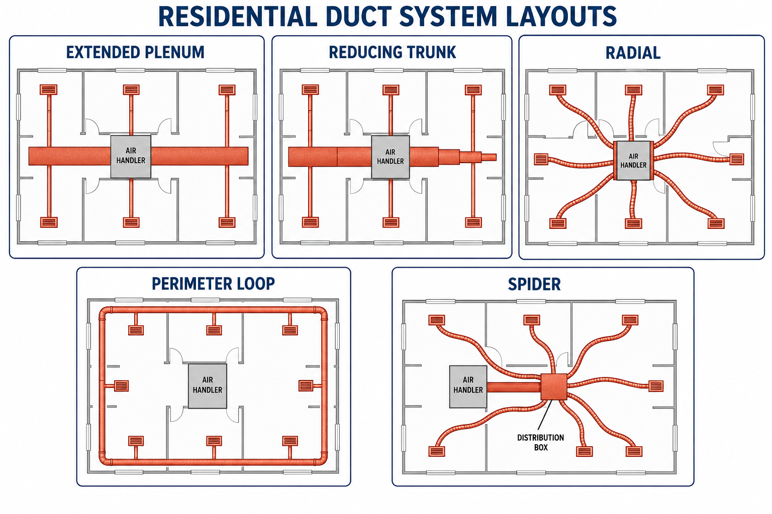
Supply-side comparison: Figure 1 emphasizes the supply layout. A complete installation must also provide an adequate return-air system and room-to-return circulation paths.
One Main Trunk Maintains Its Size
Main Arrangement
A large rectangular trunk extends from the supply plenum and maintains approximately the same dimensions through most of its length.
Branch Connections
Smaller round or rectangular branches leave the main trunk and carry air to individual supply registers or diffusers.
Common Advantages
The layout is straightforward to fabricate, install, inspect, modify, and explain to technicians and students.
Balancing Requirement
Branches at different locations and effective lengths normally require balancing dampers because available pressure is not automatically equal at every takeoff.
Common Service Points
Inspect the plenum connection, trunk end, takeoffs, branch dampers, end cap, trunk seams, and branches serving distant rooms.
Possible Complaints
Poor takeoffs, missing dampers, restrictive branches, leakage, or an improperly terminated trunk can contribute to uneven room airflow.
Branch size, fitting resistance, takeoff design, damper position, effective length, terminal resistance, leakage, and room pressure all affect the airflow delivered through each branch.
The Main Trunk Becomes Smaller After Branch Takeoffs
Main Arrangement
The trunk begins at a larger size near the equipment and reduces in steps or through transitions as branches remove airflow from the main path.
Design Purpose
Trunk reductions can maintain appropriate velocity and use material and space efficiently as less airflow remains in downstream portions.
Transition Quality
Properly shaped transitions provide a controlled change in duct area. Abrupt, poorly constructed, or internally obstructed reductions can create unnecessary resistance and turbulence.
Field Modifications
Adding a branch without evaluating the original airflow allocation can leave downstream sections and rooms with inadequate air.
Measurement Planning
Pressure measurements taken before and after reductions and branch takeoffs can help identify where excessive loss occurs.
Common Service Points
Inspect each size change, branch takeoff, damper, end section, and any transition installed close to another fitting.
Individual Branches Leave a Central Plenum
Main Arrangement
Separate round or flexible ducts leave a central supply plenum and travel directly to individual room registers without using a long main trunk.
Individual Paths
Each room branch has its own diameter, length, bends, compression, terminal, and damper position, all of which affect delivered airflow.
Installation Flexibility
Individually routed branches can simplify installation around framing, but poor routing can produce long runs, sharp bends, excessive sag, and unnecessary compression.
Balancing
Short branches can receive more air than long or restrictive branches unless the system is correctly sized and balanced.
Plenum Inspection
A large number of collars and branch connections around one plenum creates multiple possible leakage points and can make damper access difficult.
Room Diagnosis
A complaint limited to one room can often be traced along one individual branch from the plenum collar to the terminal.
A Main Duct Follows the Building Perimeter
Main Arrangement
A supply duct runs around much or all of the building perimeter, with registers or short branches serving exterior rooms and load areas.
Perimeter Delivery
Terminals near exterior walls, windows, and doors can help offset envelope loads and promote room-air mixing when properly selected and located.
Airflow Direction
Depending on the design, the loop may receive air from one point, from two directions, or through multiple connections. The actual arrangement must be traced.
Concealed Sections
Perimeter ducts may be concealed beneath slabs, within floors, above ceilings, or inside building cavities, making physical inspection and repair more difficult.
Moisture Concerns
Below-grade or slab-associated ducts require special attention to water entry, corrosion, contamination, failed joints, and inaccessible damage.
Diagnostic Planning
Register airflow, pressure comparison, leakage testing, inspection cameras, and available access points may be needed when the main loop cannot be seen directly.
A Remote Distribution Box Feeds Multiple Branches
Main Arrangement
A larger duct carries supply air from the equipment to a remote distribution box, from which multiple smaller branch ducts extend to room terminals.
Distribution Box
The box provides a central location for dividing airflow among the branch ducts and must be properly sized, supported, sealed, and connected.
Flexible Branches
Many spider systems use flexible branches whose performance depends heavily on full extension, routing, bend radius, support, and connection quality.
Access
A distribution box located in an attic or concealed area can make branch connections, balancing devices, and leakage difficult to inspect.
Possible Restrictions
An undersized feed duct, restrictive distribution box, abrupt entry, compressed branches, or too many outlets can limit the entire system.
Field Identification
Do not confuse a spider system with a true radial system that sends each branch directly from the equipment plenum.
Every Arrangement Has Different Inspection Priorities
Extended Plenum
Concentrate on trunk leakage, takeoff quality, branch dampers, end treatment, and airflow differences between near and distant branches.
Reducing Trunk
Inspect size changes, transitions, takeoff sequence, downstream airflow, and field-added branches.
Radial
Inspect each individual branch for length, bends, compression, sag, damage, leakage, damper position, and terminal condition.
Perimeter Loop
Identify feed locations, airflow direction, concealed leakage, water exposure, contamination, and inaccessible damage.
Spider
Inspect the main feed, distribution box, branch connections, flexible-duct routing, support, and balancing provisions.
Hybrid System
Sketch the actual installation and evaluate each portion according to its material, layout, fittings, airflow, and operating conditions.
Supply Air Requires a Path Back to the Equipment
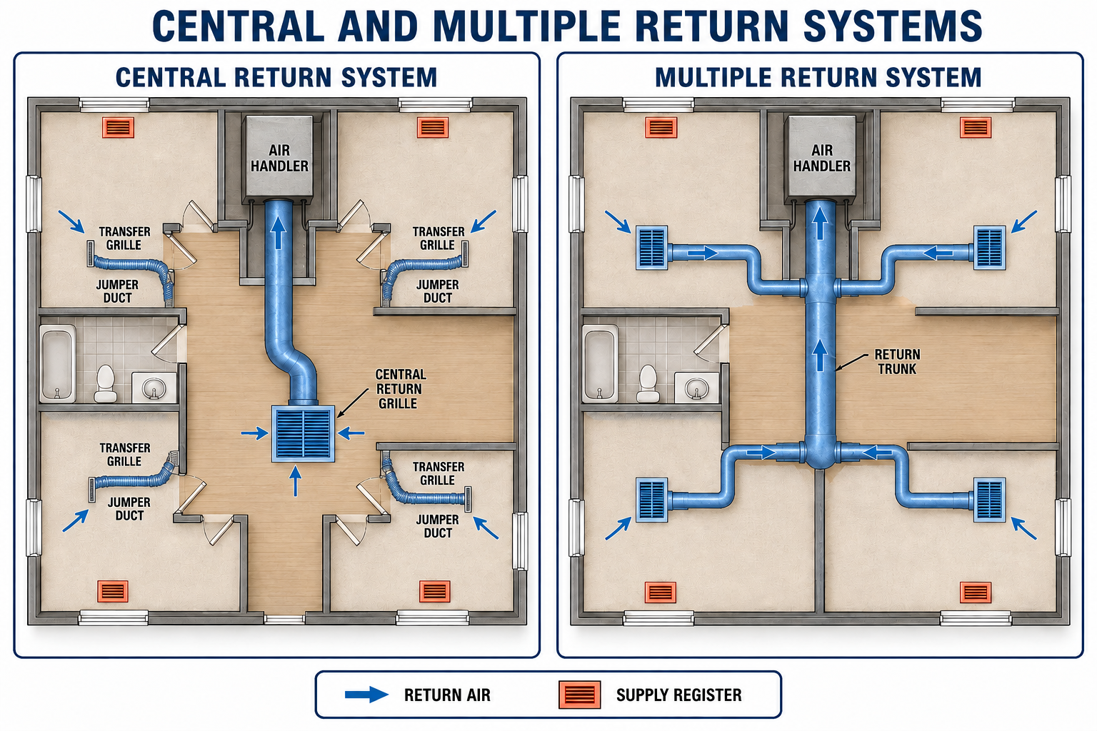
One Main Return Location
One large return grille, or a small number of central grilles, collects air from the building and connects to the equipment through a main return duct.
Several Dedicated Return Locations
Return grilles in several rooms or zones connect through branches to a common return trunk or directly to the equipment.
Rooms Must Communicate With the Central Return
Open Doorway
An open doorway can provide a return path from a room to a central return, although it cannot be assumed that doors will remain open during normal occupancy.
Transfer Grille
A transfer grille provides a permanent air opening between a closed room and an adjacent hall or common area containing the central return.
Jumper Duct
A jumper duct connects grilles on opposite sides of a wall or ceiling boundary and provides a return path while reducing direct sound and light transfer compared with a simple opening.
Door Undercut
A door undercut can pass some air, but its effective free area is often limited and must not automatically be assumed adequate for the room’s supply airflow.
Closed-Room Pressure
A closed room with supply airflow but an inadequate return path can become positively pressurized relative to the hallway or equipment area.
System Interaction
Restricted room return paths can reduce supply delivery, increase leakage to outdoors, draw outdoor air into other areas, and contribute to comfort complaints.
A central-return system may appear acceptable with every interior door open and perform poorly when bedroom or office doors are closed. Evaluate room pressure and airflow under the conditions occupants actually create.
Dedicated Returns Provide More Direct Air Paths
Room Return Grilles
Dedicated return grilles allow air to leave individual rooms without depending entirely on an open door or transfer path.
Return Branches
Each return branch adds its own length, fittings, grille resistance, leakage potential, and connection to the main return trunk.
Return Trunk
The main return trunk must carry the combined airflow from the connected branches without creating excessive resistance.
Filter Arrangements
A multiple-return system may use one central filter at the equipment, filters at return grilles, or another approved arrangement. Multiple filters must be identified before pressure-drop testing.
Balancing
Return branches influence room pressure and total airflow, but return dampers must be adjusted cautiously so the system maintains adequate equipment airflow and proper building pressure relationships.
Leakage
Return leakage can draw dust, insulation fibers, odors, moisture, attic air, crawlspace air, garage contaminants, or combustion products into the system.
The total return path remains limited by grille free area, branch sizes, fittings, trunk size, filter resistance, equipment openings, leakage, and blower performance.
Rooftop Equipment Commonly Serves Ceiling Distribution
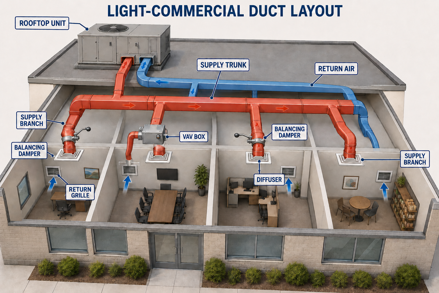
Rooftop Unit
A packaged rooftop unit commonly contains the blower, filter, heating section, cooling section, controls, and outdoor-air components within one cabinet.
Roof Curb and Openings
The roof curb supports the unit and provides aligned supply and return openings between the equipment and the building duct system.
Supply Trunk
A main supply trunk carries conditioned air through the building and feeds branch ducts serving rooms or zones.
Supply Branches
Branches connect the trunk to ceiling diffusers, registers, terminal units, or smaller downstream duct networks.
Ceiling Diffusers
Ceiling diffusers distribute air across occupied spaces and are selected for airflow, throw, spread, drop, noise, ceiling type, and room requirements.
Return Grilles
Return grilles allow room air to enter a ducted return system or an approved ceiling-return plenum before traveling back to the equipment.
Commercial Return Air May Follow Different Paths
Grilles Connect to Return Ducts
Return grilles connect through branches and trunks to the rooftop unit or air-handling equipment, providing a defined return-air pathway.
The Ceiling Space Carries Return Air
Return grilles discharge into an approved ceiling plenum, and the plenum carries air toward a return opening or duct connected to the equipment.
Materials, wiring, penetrations, cleanliness, fire and smoke protection, access, and use of the space must comply with the applicable codes and building requirements. Do not treat a return plenum as an ordinary storage or utility space.
Branches Need Controlled Adjustment
Branch Damper
A manual balancing damper is normally located in the branch duct where it can add controlled resistance without relying on the supply terminal as the primary balancing device.
Damper Position
An external handle may indicate blade position, but the actual damper and linkage must be inspected when the indication and airflow do not agree.
Access
Balancing dampers must remain accessible for adjustment and verification after ceilings, insulation, and architectural finishes are installed.
Documentation
Record the original damper position before adjustment and document the final measured airflow rather than relying only on handle angle.
Balancing distributes available airflow according to room or zone requirements. A fully open position does not prove that a branch receives the correct airflow or that the complete system has adequate total airflow.
A VAV Box Changes Zone Airflow
Variable-Air-Volume Control
A variable-air-volume box changes the airflow delivered to a zone in response to a control signal, zone demand, or operating sequence.
Primary Air Damper
An internal damper modulates the primary supply-air opening and changes the resistance and airflow through the terminal unit.
Airflow Sensor
Many VAV boxes use an airflow-sensing arrangement and controller to compare measured or inferred airflow with the zone airflow setpoint.
Downstream Distribution
One VAV box may feed one diffuser or a downstream branch system serving several diffusers within the same zone.
Reheat
Some VAV boxes include electric or hot-water reheat so supply air can be reheated when the zone requires less cooling or requires heat.
System Interaction
As VAV dampers modulate, the central fan and controls must respond so duct pressure and airflow remain within the system’s intended operating range.
Introductory scope: This lesson identifies the VAV box as part of the duct layout. Detailed VAV controls, airflow calibration, static-pressure reset, terminal operation, and system balancing require additional commercial training.
Create a Field Sketch Before Testing
- Identify the equipment type, location, orientation, and operating modes.
- Locate the supply and return openings at the equipment.
- Trace the supply plenum and determine whether the system uses a trunk, radial branches, a loop, a distribution box, or a hybrid arrangement.
- Mark every visible size change, transition, elbow, tee, wye, takeoff, offset, and end cap.
- Record branch sizes, materials, approximate lengths, visible restrictions, and terminal locations.
- Locate balancing dampers, zone dampers, VAV boxes, bypass paths, access doors, and other airflow-control devices.
- Trace each return grille toward the equipment and identify central, multiple, ducted, plenum, jumper, and transfer paths.
- Note filters, coils, heat exchangers, humidifiers, air cleaners, sound devices, and other components in the airflow path.
- Identify ducts located outside conditioned space and inspect them for leakage, insulation damage, condensation, and environmental exposure.
- Mark practical pressure, temperature, velocity, and airflow measurement locations.
- Compare the sketch with available plans, balancing reports, equipment data, and control documentation.
- Update the sketch when field observations prove that the installed arrangement differs from the plans.
A useful field sketch shows which ducts connect to which plenums, trunks, branches, terminals, zones, and equipment openings. Physical proximity does not prove that two concealed ducts are connected.
Use the Layout to Narrow the Search
One Room Has Weak Supply Airflow
Inspect that room’s register, branch damper, boot, branch duct, takeoff, fittings, leakage, flexible-duct routing, and return path.
Several Downstream Rooms Are Weak
Look for a common trunk restriction, closed damper, failed transition, crushed section, leakage, disconnected duct, undersized feed, or field-added branch.
Every Room Has Weak Airflow
Evaluate the filter, blower, coil, heat exchanger, total external static pressure, main supply and return ducts, equipment openings, and controls.
Complaint Occurs With Doors Closed
Investigate central-return access, transfer grilles, jumper ducts, door position, room pressure, and the relationship between room supply and return airflow.
One Commercial Zone Is Incorrect
Inspect the zone damper or VAV box, airflow sensor, controller, downstream branches, diffusers, reheat operation, and zone-return path.
System Is Noisy
Check duct velocity, restrictive fittings, damper position, terminal selection, flex compression, turbulence near takeoffs, leakage, vibration, and fan operation.
Layout Errors to Avoid
“Every system fits one exact category.”
Many installations combine trunk, radial, flexible, central-return, multiple-return, and later-modified sections.
“A branch close to the blower always receives the most air.”
Airflow depends on the complete branch path, fittings, damper position, terminal resistance, pressure distribution, and interaction with the other branches.
“A central return works whenever the hallway grille is large.”
Air from closed rooms still needs an adequate path to reach the central grille.
“Several return grilles guarantee adequate return airflow.”
The return branches, trunk, filter, equipment opening, fittings, and blower must support the required combined airflow.
“A rooftop unit always uses a ceiling-plenum return.”
Commercial systems can use fully ducted returns, approved ceiling plenums, or combinations of the two.
“The plans prove how the system is connected.”
Plans are valuable references, but field changes and concealed modifications require verification of the installed system.
Can You Identify the Layout?
- How does an extended-plenum system differ from a reducing-trunk system?
- What distinguishes a radial system from a spider system?
- Why do branches in an extended-plenum system still require balancing?
- What should be inspected at each reduction in a reducing trunk?
- Why can flexible-duct installation quality be especially important in radial and spider systems?
- What additional concerns apply to concealed or below-grade perimeter ducts?
- How does a central-return system move air from a closed bedroom to the return grille?
- What happens when a room receives supply air without an adequate return path?
- Why do multiple return grilles not automatically guarantee adequate total return airflow?
- How does a ducted commercial return differ from a ceiling-plenum return?
- What is the basic purpose of a VAV box?
- What information belongs on a technician’s field sketch of an unfamiliar system?
What You Should Have Learned
Extended-plenum and reducing-trunk systems use main trunks, while radial and spider systems distribute air through multiple individual branches.
A radial system sends branches directly from the equipment plenum, while a spider system uses a separate distribution box supplied by a larger feed duct.
A perimeter-loop system distributes air around much or all of the building perimeter and may contain concealed sections requiring specialized inspection.
A central-return system depends on open doorways, transfer grilles, jumper ducts, or other designed paths from closed rooms to the central grille.
A multiple-return system uses dedicated room returns but remains limited by its branches, trunk, filters, fittings, equipment opening, and blower performance.
Light-commercial systems commonly use rooftop equipment, supply and return trunks, branches, diffusers, balancing dampers, and zone-control components.
A VAV box changes airflow to a zone and may include airflow sensing, controls, and reheat.
A technician should trace and sketch the installed system rather than assuming that its name or original plan completely describes its current configuration.