Airflow Through Cooling and Heating Equipment
A duct system does more than deliver air to the rooms. It must move the correct amount of air through filters, blowers, evaporator coils, heat exchangers, electric heaters, and other components before useful heating or cooling can reach the occupied space.
This lesson follows the air through common residential and light-commercial equipment and explains how airflow affects cooling capacity, moisture removal, temperature rise, safety controls, comfort, and equipment reliability. The emphasis is on what a service technician must observe, measure, and verify.
What You Will Learn
By the end of this lesson you should be able to:
Trace the complete air path.
Follow return air through the filter, blower, conditioning components, supply duct, and occupied space.
Explain cooling airflow.
Describe how airflow affects sensible capacity, latent capacity, coil temperature, condensate, and freeze risk.
Explain heating airflow.
Relate airflow to furnace temperature rise, heat-exchanger temperature, electric-heat operation, and heat-pump performance.
Recognize airflow restrictions.
Identify filters, coils, fittings, dampers, grilles, and undersized ducts that can reduce system airflow.
Use equipment data correctly.
Select the required airflow and blower setting from the approved equipment instructions, performance tables, and nameplate information.
Plan a technician diagnosis.
Use temperatures, pressure measurements, blower data, operating conditions, and direct airflow tests to evaluate the air side.
Every Component Uses Part of the Blower’s Available Pressure
Return System
Return grilles, ducts, fittings, dampers, and filter assemblies carry air from the occupied space to the equipment.
Air-Moving Equipment
The blower creates the pressure difference needed to move air through the equipment and duct system.
Conditioning Components
Coils, heat exchangers, electric heaters, humidifiers, and air-cleaning devices transfer energy or treat the airstream while adding resistance.
Supply System
Supply plenums, trunks, branches, fittings, dampers, boots, grilles, and registers distribute conditioned air to the rooms.
A blower setting does not guarantee a particular airflow. Actual airflow depends on the blower’s performance at the resistance imposed by the installed equipment, filter, return system, and supply system.
Airflow Through an Evaporator Coil
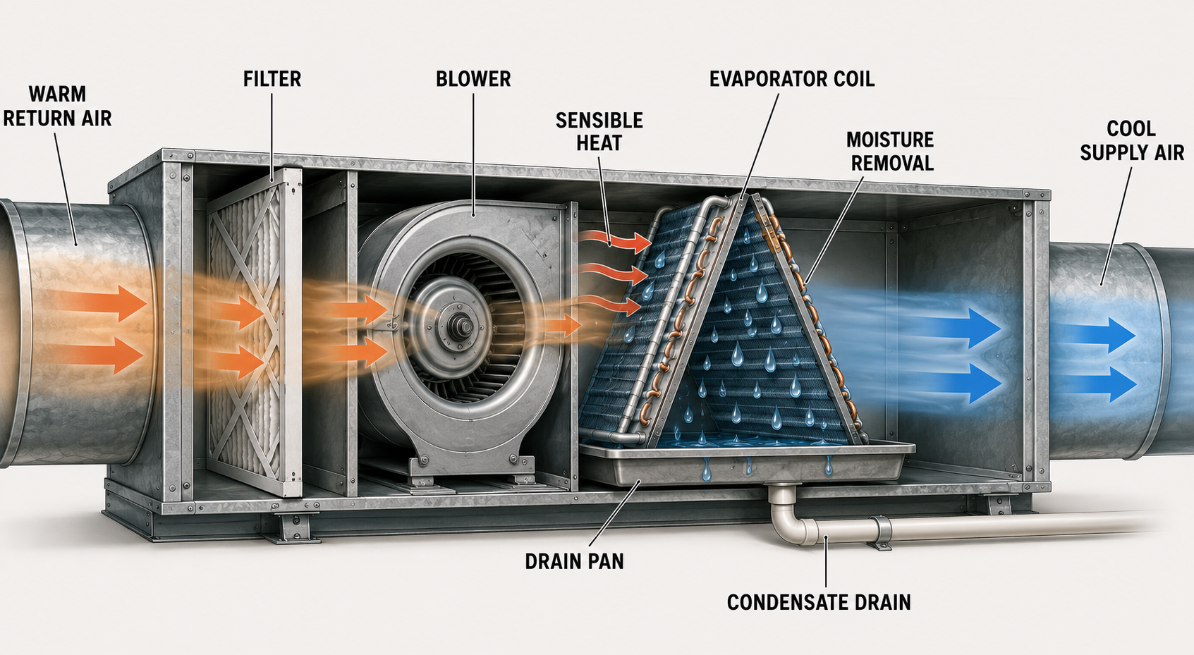
The evaporator does not cool air merely because refrigerant is flowing. Heat transfer requires the correct mass of air to pass across a clean coil at the operating conditions for which the matched equipment was designed. The blower, coil, refrigerant circuit, duct system, and building load operate as one system.
Air Temperature Decreases
The coil removes sensible heat from the airstream. Airflow, entering-air condition, coil temperature, and refrigerant-side operation all affect the leaving-air temperature.
Moisture Condenses
When the coil surface is below the entering air’s dew point, water vapor condenses on the coil and drains through the condensate system.
Approximately 400 CFM per nominal ton is a familiar starting reference, not a universal commissioning value. Required airflow varies with the matched equipment, sensible and latent load, selected mode, blower setup, available static pressure, and manufacturer instructions. Some applications intentionally use a different airflow, and multi-stage or variable-capacity equipment may use several airflow targets.
Too Little and Too Much Airflow Produce Different Problems
Less Heat Reaches the Coil
Low airflow can lower the evaporating temperature, reduce total capacity, increase the air-temperature change, encourage frost or ice formation, and produce poor room circulation. Causes can include a dirty or restrictive filter, dirty coil, incorrect blower setup, closed dampers, blocked grilles, duct restrictions, or a blower problem.
More Air Passes Across the Coil
Excess airflow may reduce the air-temperature change and moisture removal, increase air noise, create register drafts, and move the blower outside the intended operating range. It may also reveal that blower setup or duct balancing does not match the equipment and load.
Do not diagnose airflow from temperature split alone. A large or small return-to-supply temperature difference can be influenced by airflow, entering wet-bulb and dry-bulb conditions, refrigerant charge, metering-device operation, coil condition, compressor capacity, duct heat gain, and measurement location.
Airflow Carries Heat Away from the Equipment
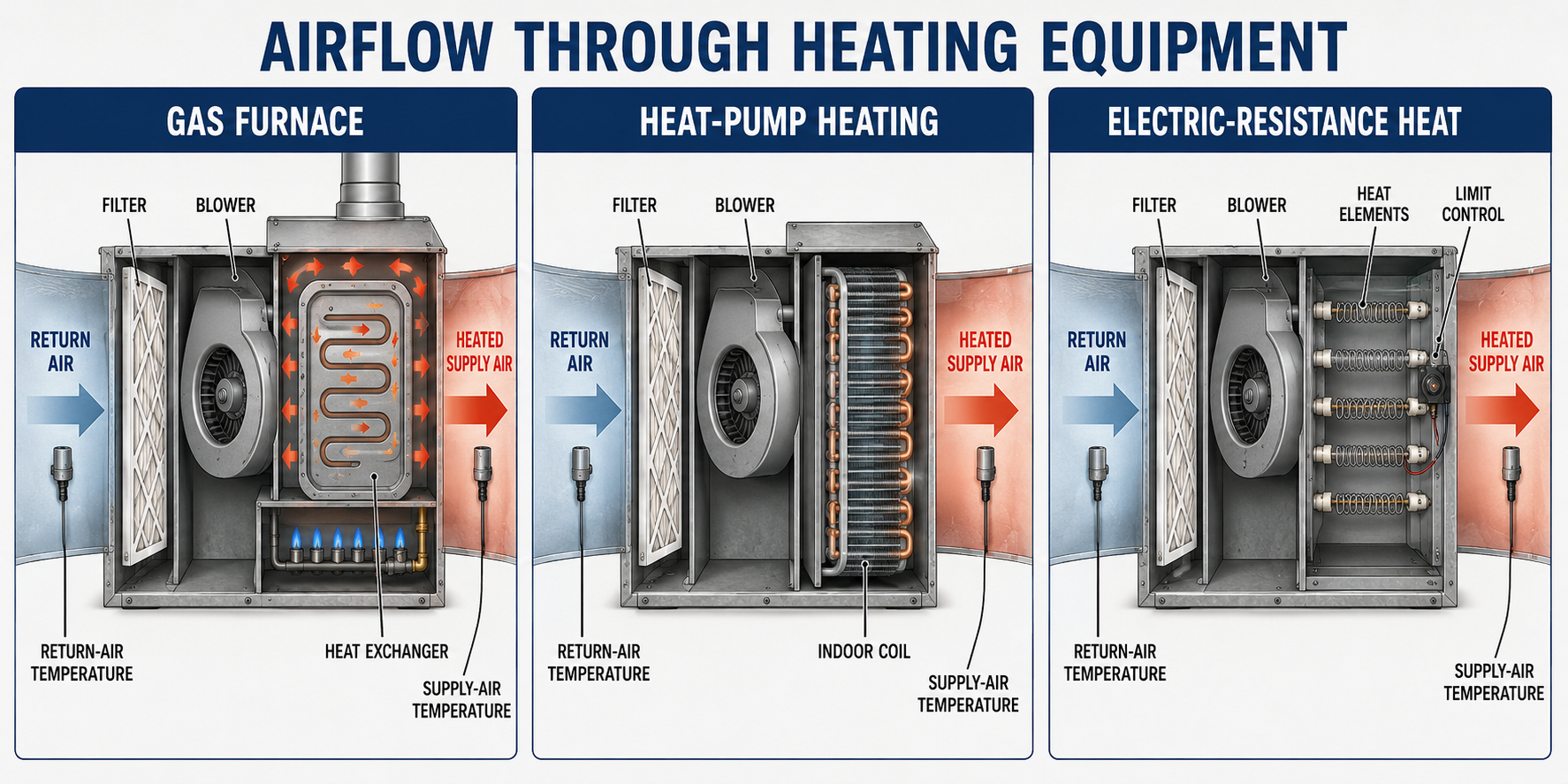
Gas or Oil Furnace
Return air passes around the outside of the heat exchanger and carries combustion-produced heat into the supply duct. The circulating air must never mix with flue gases inside a sound heat exchanger.
Electric Resistance Heat
Air passes across energized heating elements. The approved minimum airflow, staging, blower interlocks, and limit controls are essential to prevent excessive element and cabinet temperatures.
Heat Pump
In heating mode, the indoor refrigerant coil transfers heat to the airstream. Delivered-air temperature is commonly lower than that of a fossil-fuel furnace, even when the system is operating correctly.
Hydronic Air Handler
Air passes across a water coil supplied by a boiler or water heater approved for the application. Airflow, water temperature, water flow, and coil condition jointly determine delivered capacity.
Use the Nameplate Range as an Operating Requirement
Furnace temperature rise is the difference between the air temperature entering the furnace and the air temperature leaving the furnace after the system reaches stable operation. Measure in representative airstream locations that are not distorted by radiant heat, bypass air, an evaporator coil, humidifier, or a direct line of sight to the heat exchanger.
Leaving Air − Entering Air
Compare the measured result with the range printed on the furnace rating plate and the exact model’s installation instructions.
Rise Usually Increases as Airflow Decreases
For a stable heat input, less airflow must absorb the heat, so each unit of air experiences a greater temperature increase.
Check Airflow Before Changing Fuel Input
Possible causes include an obstructed filter or coil, incorrect blower speed, closed dampers, blocked grilles, an undersized duct system, a blower fault, excessive external static pressure, or excessive input. High temperature rise can contribute to limit cycling and heat-exchanger stress.
Verify Both Airflow and Heat Input
Possible causes include excessive airflow, incorrect blower setup, low fuel input, burner problems, low gas pressure, duct leakage, or measurement error. Follow the manufacturer’s combustion and input-checking procedures.
A furnace high-limit switch protects against abnormal temperature. Repeated limit opening is a fault condition to diagnose, not an acceptable method of regulating normal operation. Never bypass a limit or operate equipment outside its approved temperature-rise range.
One Indoor Blower May Need Several Airflow Settings
Continuous Fan
Fan-only airflow may be lower than cooling airflow to reduce noise and power consumption while circulating and filtering air.
First-Stage Cooling
Two-stage equipment normally uses a reduced airflow matched to first-stage compressor capacity.
Full Cooling
High-stage or full-capacity cooling requires the airflow specified for the matched indoor coil and outdoor unit.
Heat-Pump Heating
Heating airflow may differ from cooling airflow and may change as compressor capacity, outdoor conditions, or auxiliary heat stages change.
Furnace Heating
Heating speed must keep the furnace within the approved temperature-rise range at each firing stage.
Electric Auxiliary Heat
Controls must provide at least the airflow required for the connected heater size and installed configuration.
Blower taps, dip switches, airflow-selection pins, thermostat signals, communicating-control settings, motor profiles, and programmed delays may determine airflow. A replacement component can operate electrically while still being configured incorrectly for the installed equipment.
Air Must Reach the Equipment Before It Can Be Conditioned
The return-air filter protects the blower and conditioning surfaces while removing particles from the airstream. MERV, or Minimum Efficiency Reporting Value, describes particle-removal performance under the ASHRAE 52.2 test method. MERV does not state whether a particular filter will fit the system’s available pressure budget.
What the Filter Captures
A higher MERV rating generally identifies greater removal efficiency for smaller particles within the test method’s rating ranges.
What the Blower Must Overcome
Pressure drop is the loss in total pressure across the filter at a stated airflow or face velocity. It depends on filter construction, size, surface area, airflow, installation, and dust loading—not on MERV alone.
Use the filter manufacturer’s pressure-drop data and verify that the equipment and duct system can maintain required airflow. A larger filter or deeper media cabinet can provide more surface area and may produce less resistance than a small filter with the same MERV rating. Measure actual pressure drop when diagnosing the installed system.
Evaluate Airflow Before Adjusting the Refrigerant Circuit
- Identify the exact indoor and outdoor equipment, matched components, heating input, electric-heater size, motor type, and control configuration.
- Determine the required airflow or approved temperature-rise range from the rating plate and manufacturer instructions.
- Confirm the operating mode, stage, thermostat signals, blower commands, programmed delays, and zoning position.
- Inspect the filter for correct size, direction, fit, cleanliness, bypass, MERV rating, and available pressure-drop data.
- Inspect return and supply grilles, dampers, ducts, flexible connectors, coils, blower wheel, heat exchanger, and accessories for restrictions or leakage.
- Measure total external static pressure and individual component pressure drops at the correct test locations.
- Use the manufacturer’s blower table, fan curve, motor data, or approved commissioning procedure to interpret the pressure measurement.
- Measure airflow directly when required with an appropriate method such as a flow hood, duct traverse, or another manufacturer-approved procedure.
- Measure return and supply temperatures at representative locations and compare cooling operation or furnace temperature rise with approved data.
- Correct the proven cause, restore all panels and dampers, and repeat measurements under stable operating conditions.
Diagnostic sequence matters: Incorrect airflow changes refrigerant pressures, superheat, subcooling, coil temperature, compressor loading, and temperature split. Charging or replacing refrigerant-side components before verifying airflow can hide the original problem and create a second fault.
Errors That Lead to Misdiagnosis
“The blower is running, so airflow is adequate.”
A blower can run against excessive resistance and deliver far less air than the equipment requires.
“Every cooling system needs exactly 400 CFM per ton.”
The correct target comes from the matched-equipment data and application requirements.
“A higher-MERV filter is automatically better.”
Filtration efficiency and pressure drop are separate characteristics; the installed system must accommodate both.
“A high furnace temperature rise proves a bad heat exchanger.”
Temperature rise is affected by airflow and heat input and does not by itself establish heat-exchanger condition.
“An ECM always delivers the correct airflow.”
A constant-airflow ECM can compensate only within its programmed range and available capability; configuration and excessive static pressure still matter.
“A normal temperature split proves correct airflow.”
Different combinations of load, airflow, coil condition, and refrigerant operation can produce similar temperature readings.
Can You Follow Air Through the Equipment?
- Why does a selected blower speed not guarantee a specific airflow?
- What two types of heat may be removed as air passes through an evaporator coil?
- Why is 400 CFM per ton a reference rather than a universal requirement?
- Name four conditions that can cause low cooling airflow.
- How can excessive cooling airflow affect moisture removal?
- How is furnace temperature rise calculated?
- Where is the acceptable furnace temperature-rise range found?
- Why may a heat pump’s supply air feel cooler than furnace supply air?
- What does MERV describe, and what does it not describe?
- Why must filter pressure drop be evaluated at the system’s airflow?
- Why should airflow be verified before refrigerant charge is adjusted?
- What measurements can a technician combine to evaluate equipment airflow?
What You Should Have Learned
The blower, equipment components, return duct, supply duct, and occupied space form one connected airflow system.
Cooling airflow affects sensible capacity, latent capacity, coil temperature, condensate formation, comfort, and freeze risk.
Required cooling airflow must come from matched-equipment and manufacturer data rather than a universal CFM-per-ton rule.
Heating equipment requires enough airflow to transfer heat safely and deliver the intended capacity.
Furnace temperature rise must remain within the rating-plate range and must be measured at representative locations.
One blower may use different airflow settings for fan-only, cooling, heat-pump heating, furnace heating, staging, and auxiliary heat.
MERV describes particle-removal performance, while filter pressure drop describes resistance to airflow.
A reliable diagnosis combines equipment data, inspection, pressure, temperature, blower performance, and direct airflow measurements as needed.