Static, Velocity, and Total Pressure
Air moves through a duct system because the blower creates a pressure difference. The air possesses pressure associated with its condition and pressure associated with its motion, and both must be understood before a technician can interpret duct measurements correctly.
This lesson distinguishes static pressure, velocity pressure, and total pressure; introduces inches of water column and pascals; and explains how the blower adds pressure while ducts and passive components consume it. Later lessons will apply these fundamentals to positive and negative pressure, field instruments, static-pressure testing, total external static pressure, and restriction diagnosis.
What You Will Learn
By the end of this lesson you should be able to:
Define static pressure.
Describe the portion of air pressure associated with the air’s condition rather than its motion.
Define velocity pressure.
Relate the kinetic energy of moving air to air velocity and recognize that velocity pressure is always positive.
Define total pressure.
Use the algebraic relationship among total, static, and velocity pressure at the same point.
Recognize pressure units.
Read small HVAC air pressures in inches of water column and pascals without confusing units or decimal places.
Explain pressure loss.
Describe why total pressure decreases as air passes through ducts, fittings, and passive system components.
Connect pressure with airflow.
Explain why a pressure reading alone does not establish CFM without additional equipment or duct information.
The Blower Creates a Pressure Difference
Air does not move through a duct because it has been commanded to move. The blower transfers mechanical energy to the airstream and creates a difference in pressure. Air then moves through the available path while the duct system and its components resist that movement.
Blower
The blower is the primary source of mechanical energy in the air-distribution system and produces a pressure rise from its inlet to its outlet.
Airflow Path
Return ducts carry air toward the blower, and supply ducts carry air away from the blower to the occupied spaces.
System Resistance
Duct surfaces, filters, coils, heat exchangers, fittings, dampers, grilles, and registers resist movement and consume pressure.
Airflow Result
Actual airflow is determined by the interaction between blower performance and the resistance of the complete installed air path.
Pressure helps produce airflow, but a static-pressure reading is not a CFM reading. The same pressure can be associated with different airflows when blower characteristics, duct size, system configuration, or operating mode differ.
Three Ways to Describe Pressure in Moving Air
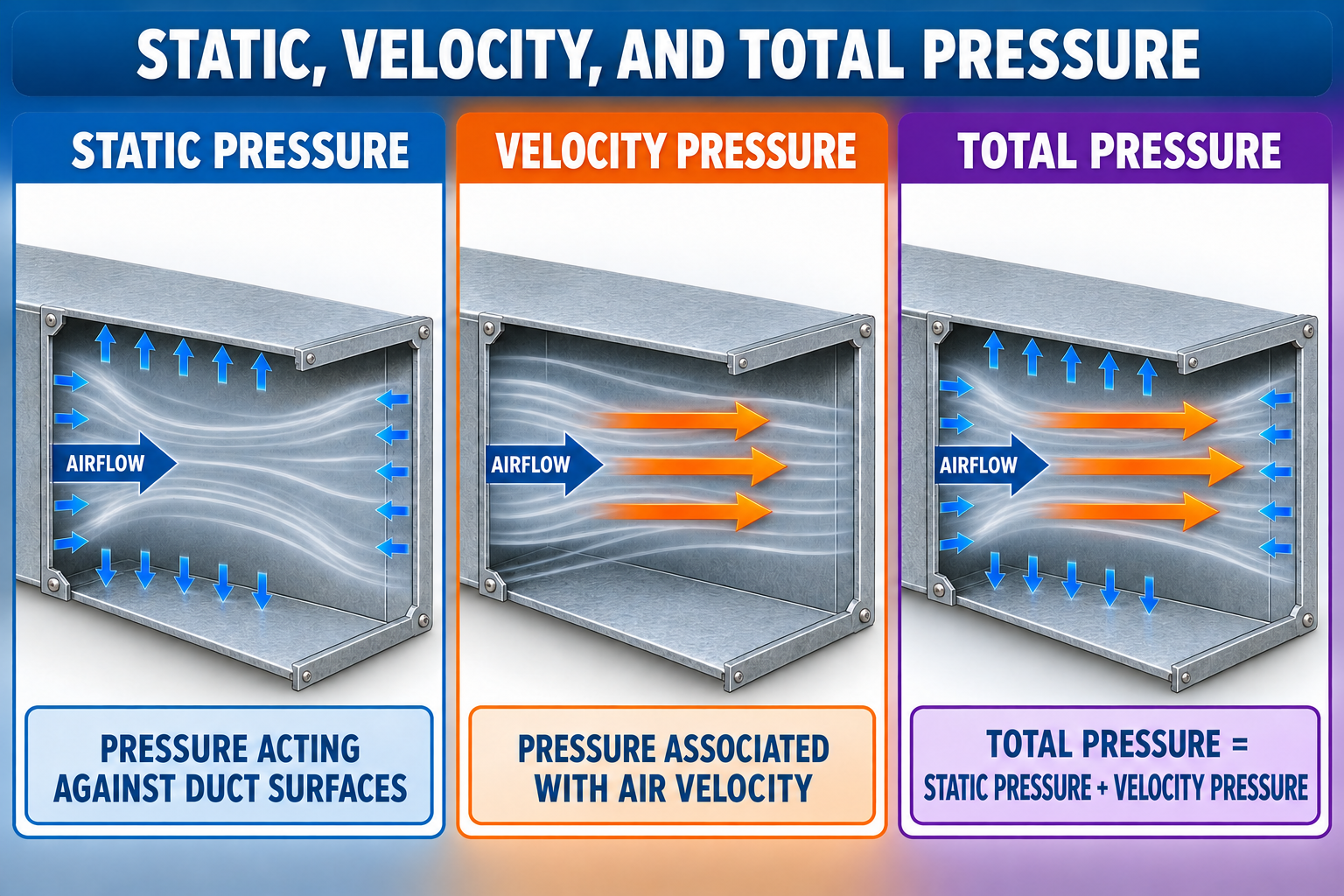
Static Pressure
Static pressure is associated with the air’s state rather than its motion. It acts in all directions and pushes against duct walls and component surfaces.
Velocity Pressure
Velocity pressure represents the kinetic energy of moving air. It is related to air velocity and is always a positive value.
Total Pressure
Total pressure represents the combined static and velocity pressure at the same location in the airstream.
Pt = Ps + Pv
Total pressure equals static pressure plus velocity pressure using algebraic values.
Pv = Pt − Ps
Velocity pressure equals total pressure minus static pressure at the same point.
Pressure Exerted Against the Duct
Static pressure is the pressure technicians measure most often in residential and light-commercial air systems. It is used to evaluate how much resistance the blower is working against and to compare pressure on opposite sides of equipment or duct components.
Acts in All Directions
Static pressure acts against the duct walls as well as against surfaces within the airstream.
May Be Positive or Negative
The sign depends on whether pressure at the test point is above or below the selected reference pressure.
Measured with a Static Probe
A properly designed and positioned probe senses static pressure while minimizing the effect of air striking the probe.
Used for Diagnostics
Static-pressure measurements support total external static pressure, component pressure-drop, blower-performance, and duct-restriction evaluations.
The sign requires a reference. Positive and negative duct pressure will be developed fully in Lesson 6. For now, remember that pressure cannot be called positive or negative unless the comparison pressure is identified.
Pressure Representing Air Motion
Moving air possesses kinetic energy. Velocity pressure is the pressure equivalent of that motion. As air velocity increases, velocity pressure increases rapidly; doubling velocity produces approximately four times the velocity pressure when air density remains the same.
Lower Velocity Pressure
Comfort-system ducts often operate with velocity pressures of only a few hundredths of an inch of water column, requiring suitable instrument resolution and careful technique.
Higher Velocity Pressure
Higher air velocity increases velocity pressure and can also contribute to greater friction, turbulence, noise, and fitting losses.
Velocity ≈ 4005 × √Pv
Velocity is in feet per minute when velocity pressure is in inches of water column and standard-air assumptions apply.
CFM = Average FPM × Area
Airflow requires representative average velocity and actual duct cross-sectional area.
Velocity varies across a duct. An accurate duct-airflow determination normally requires an approved multipoint traverse, correct duct area, appropriate density treatment, and a test location with a usable velocity profile.
The Combined Mechanical Energy of the Airstream
Total pressure includes both static pressure and velocity pressure. It is useful for following the energy supplied by the blower because it accounts for pressure stored in the air and pressure represented by motion.
Total Pressure Decreases
A duct, filter, coil, damper, fitting, grille, or register cannot add mechanical energy to the airstream. Friction and turbulence cause total-pressure loss in the direction of airflow.
Total Pressure Increases
The blower transfers mechanical energy to the air and produces a total-pressure rise from its inlet to its outlet.
Total pressure equals static plus velocity pressure. Total external static pressure, introduced in Lesson 9, is an established industry term for a static-pressure difference measured across defined equipment boundaries.
Probe Openings Determine What Is Measured
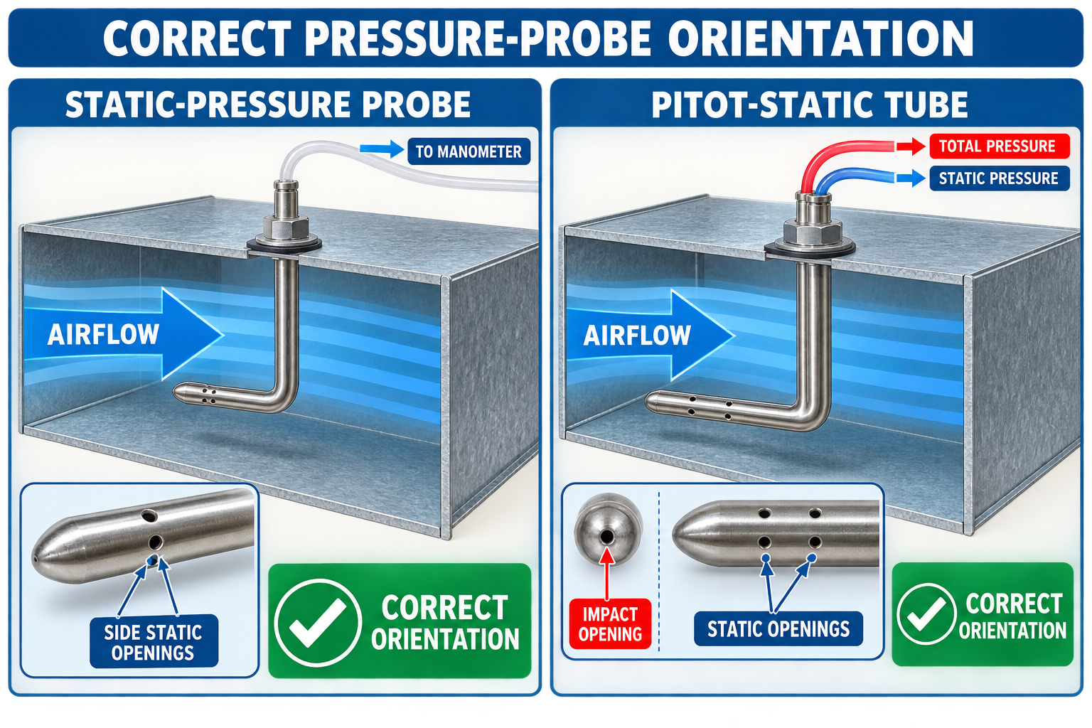
Static-Pressure Openings
Static openings are positioned so they sense pressure perpendicular to the local airflow rather than the direct impact of moving air.
Total-Pressure Opening
The total-pressure opening faces directly upstream into the moving air and senses static plus velocity pressure.
Pitot-Static Tube
A Pitot-static tube provides separate total- and static-pressure connections so their difference can be measured as velocity pressure.
Orientation Error
Misalignment, blocked openings, duct-wall contact, swirl, and turbulence can prevent the probe from sensing the intended pressure.
This is a pressure-concept introduction. Instrument selection is covered in Lesson 7, and test-hole selection and static-probe placement are covered in Lesson 8.
HVAC Air Pressures Are Small
Residential and light-commercial duct pressure is commonly expressed in inches of water column. The unit may appear as in. w.c., in. wg, in. H2O, or a similar notation. Metric instruments and technical documents commonly use pascals.
1.00 in. w.c.
The pressure capable of supporting approximately a one-inch vertical column of water under the unit’s defined conditions.
Approximately 249 Pa
One inch of water column is approximately 249 pascals.
0.50 in. w.c.
Approximately 125 Pa. This is a familiar example value, not a universal allowable pressure for every system.
0.05 in. w.c.
Approximately 12.5 Pa. The extra zero changes the value by a factor of ten.
Instrument Unit
Confirm the displayed unit before recording or comparing a measurement.
Comparison Data
Use the same unit as the equipment or component data whenever practical to avoid conversion and decimal errors.
A note that says only “0.4 pressure” is incomplete. Record the pressure type, sign when applicable, value, unit, location, reference, and operating condition.
The System Spends the Pressure Added by the Blower
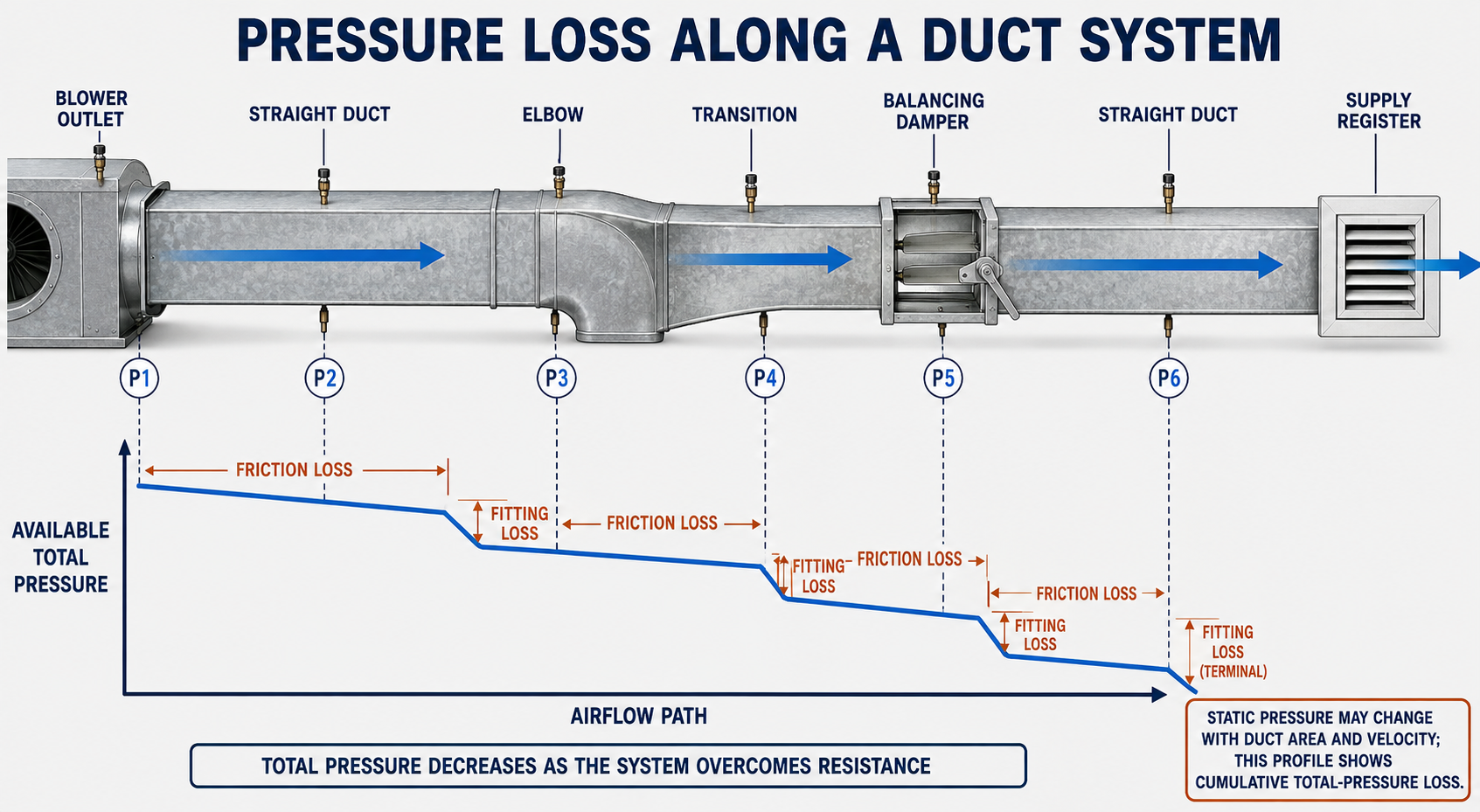
Straight Duct
Surface friction and internal turbulence produce pressure loss as air travels through a length of duct.
Fittings
Elbows, takeoffs, tees, transitions, offsets, entries, and branches change air direction or velocity and produce additional loss.
Equipment Components
Filters, coils, heat exchangers, electric heaters, humidifiers, and air cleaners add resistance to the air path.
Control and Terminal Devices
Dampers, grilles, registers, diffusers, and balancing devices consume pressure while controlling, directing, or distributing airflow.
A duct or component does not have one fixed pressure drop at every CFM. As airflow and velocity increase, friction and fitting losses increase. This is why a pressure reading must be interpreted with the actual operating condition.
Duct Area Can Change the Form of Pressure
Velocity Usually Increases
When the same airflow passes through a smaller duct area, air velocity and velocity pressure increase. Some static pressure is converted into velocity pressure while the transition also produces loss.
Velocity Usually Decreases
When the same airflow enters a larger area, velocity pressure decreases and part of it may be recovered as static pressure. Friction and turbulence prevent complete recovery.
Total pressure decreases through passive resistance, but static pressure may rise or fall locally as duct area and velocity change. Test locations and pressure type must therefore match the question being investigated.
System Resistance Changes Delivered Airflow
A blower operates where its performance capability intersects the resistance of the installed system. Changing a filter, closing dampers, crushing flexible duct, adding a coil, or changing the blower command moves the system to a different operating condition.
PSC Blower
A fixed-speed permanent split capacitor blower commonly delivers less airflow as external resistance increases.
Constant-Torque ECM
A constant-torque motor responds differently from a PSC motor but still does not guarantee one airflow at every pressure.
Constant-Airflow ECM
A programmed motor can increase speed and power to maintain airflow through part of its range but eventually reaches a capability limit.
Manufacturer Data
Blower tables or fan curves relate airflow to pressure for specific equipment, motor settings, modes, and configurations.
Do not diagnose from “high” or “low” pressure alone. The equipment model, blower type, airflow command, test location, operating mode, and manufacturer data determine what the reading means.
Identify the Measurement Before Interpreting the Number
- Identify whether the value is static pressure, velocity pressure, total pressure, or a pressure difference.
- Identify the pressure reference and retain any positive or negative sign.
- Confirm that the unit and decimal place match the comparison data.
- Record the exact test location and its position relative to the blower, duct, fitting, and equipment components.
- Record operating mode, stage, blower setting, filter condition, damper positions, panels, zones, and system stability.
- Determine whether the probe and opening were capable of sensing the intended pressure.
- Compare the value with the exact equipment, component, fan, design, or test-procedure data that applies.
- Use airflow, temperature, equipment operation, and additional pressure measurements to confirm the conclusion.
The pressure type, reference, sign, unit, location, operating condition, and comparison source must all be known before the reading can support a technical conclusion.
Pressure Errors to Avoid
“Static pressure is airflow.”
Static pressure is not CFM. Airflow can be estimated only when pressure is combined with applicable blower or duct information.
“More static pressure always means more airflow.”
Greater system resistance commonly reduces airflow from fixed-speed blowers, while some ECMs compensate only within their operating capability.
“Velocity pressure can be negative.”
Velocity pressure represents kinetic energy and is always positive, even when gauge static pressure is negative.
“Total pressure means TESP.”
Total pressure equals static plus velocity pressure; TESP is a later equipment static-pressure measurement.
“Static pressure always falls in airflow direction.”
Total pressure falls through passive resistance, but local static pressure can increase when velocity pressure is converted into static pressure.
“Every residential system should measure 0.50 in. w.c.”
Equipment ratings and approved operating pressures vary. No single static-pressure value applies to every unit or test location.
Can You Distinguish the Three Pressures?
- What creates the pressure difference that moves air through a forced-air duct system?
- What portion of the airstream’s pressure acts against the duct walls?
- What does velocity pressure represent?
- Can velocity pressure be negative?
- What is the relationship among total, static, and velocity pressure?
- How is velocity pressure determined from total and static pressure?
- What probe opening faces directly into the airflow?
- Approximately how many pascals equal one inch of water column?
- Why does one velocity reading not normally establish duct CFM?
- Why does total pressure decrease through a passive duct component?
- How can static pressure increase while total pressure decreases?
- Why must a pressure reading be interpreted with operating and equipment information?
What You Should Have Learned
The blower adds mechanical energy and creates the pressure difference needed to move air through the system.
Static pressure is associated with the air’s state, acts in all directions, and may be positive or negative relative to a reference.
Velocity pressure represents the kinetic energy of moving air and is always positive.
Total pressure is the algebraic sum of static pressure and velocity pressure at the same point.
HVAC duct pressure is commonly expressed in inches of water column or pascals, with one inch of water approximately equal to 249 pascals.
The blower produces a pressure rise, while ducts, fittings, and passive components produce total-pressure loss.
Changes in duct area can convert static pressure and velocity pressure while friction and turbulence continue to reduce total pressure.
Pressure supports airflow diagnosis only when pressure type, reference, sign, unit, location, operating condition, and comparison data are known.