PV Modules, Strings, and Arrays
A photovoltaic system begins with individual PV modules, but the electrical characteristics encountered by a technician depend on how those modules are connected together. Modules may be connected in series to form strings, multiple strings may be combined in parallel, and the complete group of modules becomes the PV array.
For troubleshooting, these relationships are important because series connections primarily affect voltage while parallel connections primarily affect available current. Understanding the physical and electrical organization of the array allows the technician to predict reasonable measurements and recognize when one string or portion of the array is operating differently from the others.
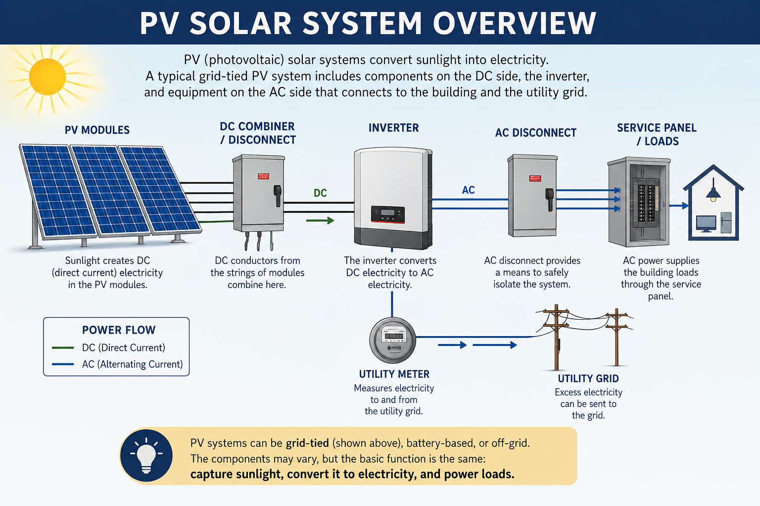
From One Module to a Complete Array
A single PV module produces a limited amount of voltage, current, and power. To obtain the electrical characteristics required by the system, modules are interconnected into larger electrical groups.
In a conventional string-inverter installation, modules are commonly connected in series to increase DC voltage. Multiple strings may then operate on separate inverter inputs or be combined in parallel to increase available current. The technician needs to understand these relationships before interpreting voltage or current measurements.
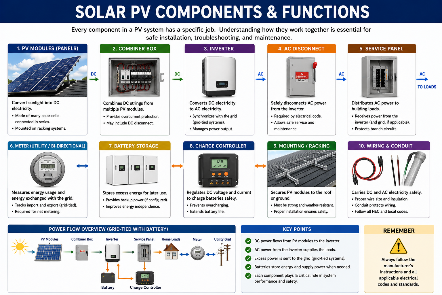
The Basic Generating Component
A photovoltaic module contains multiple solar cells electrically interconnected and packaged into a weather-resistant assembly. The module converts solar radiation into DC electrical power and provides that power through its output conductors and connectors.
For field service, the module is an important reference point because its nameplate identifies electrical ratings that help the technician estimate reasonable module, string, and array performance.
PV Cells
Semiconductor devices within the module convert solar energy directly into DC electrical energy.
Module Output
The interconnected cells provide the voltage and current available at the module output conductors.
Junction Box
The rear module junction box provides the internal transition between the cell circuits and the external output conductors.
PV Connectors
Weather-resistant connectors provide the field connections between modules, strings, optimizers, microinverters, or other PV equipment.
Know the Ratings Before Interpreting a Measurement
A technician should record the module manufacturer, model, and important electrical ratings whenever module-level troubleshooting is required. The values on the nameplate or manufacturer specification sheet establish the reference needed to determine whether a field measurement is reasonable.
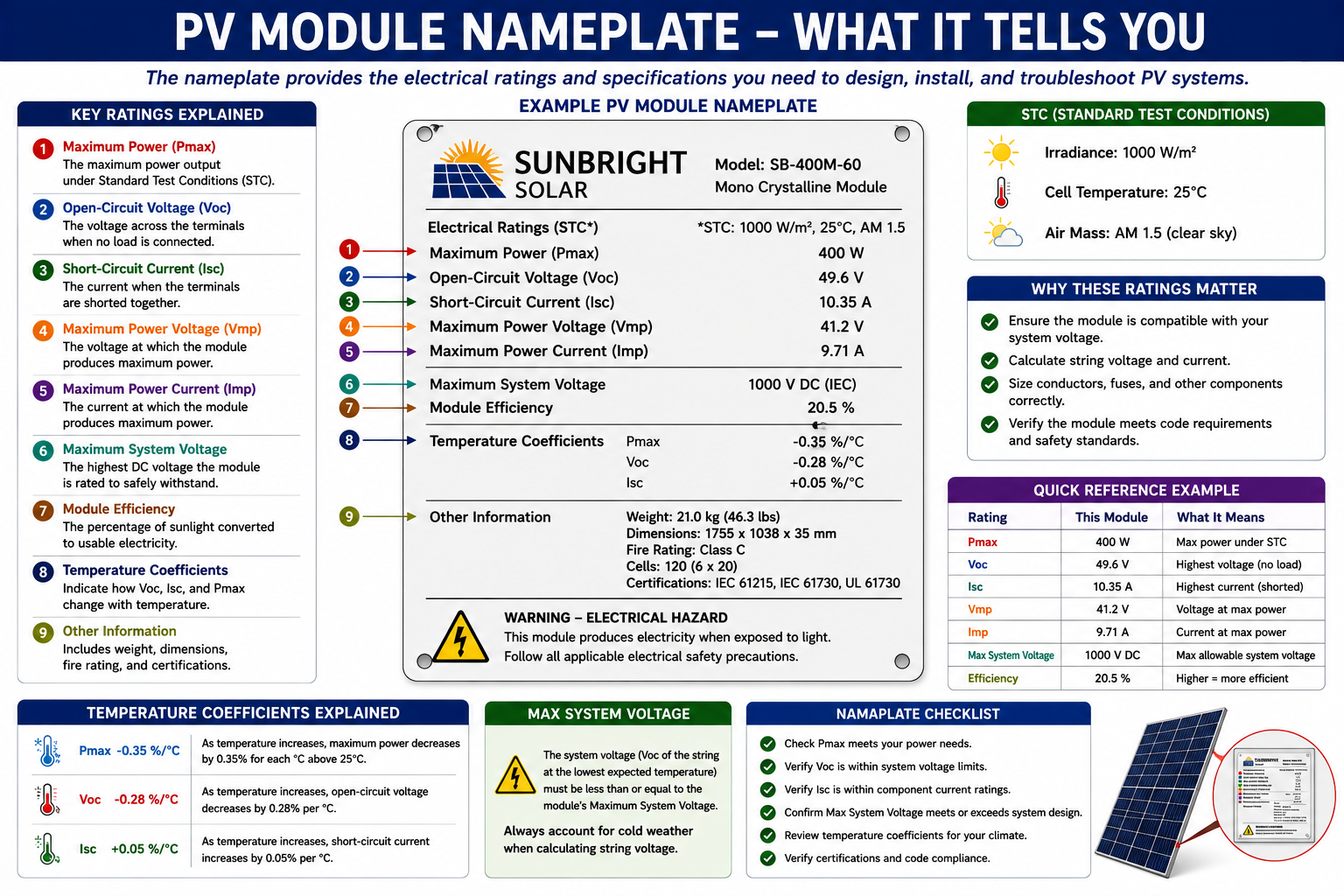
Pmax — Maximum Power
The module’s rated maximum power under the specified test conditions, commonly expressed in watts.
Voc — Open-Circuit Voltage
The DC voltage across the module when the circuit is open and essentially no load current is flowing.
Vmp — Maximum-Power Voltage
The approximate module voltage at its maximum-power operating point under the specified rating conditions.
Isc — Short-Circuit Current
The module’s rated current under specified short-circuit test conditions. This is a specification value, not an instruction to short-circuit a module during routine troubleshooting.
Imp — Maximum-Power Current
The approximate module current at its maximum-power operating point under the specified rating conditions.
Maximum System Voltage
A system limitation associated with the module and installation. It is not the normal operating voltage of one individual module.
Modules in Series Increase String Voltage
A conventional PV string is formed by connecting modules in series. The positive output of one module connects to the negative output of the next, creating one continuous electrical path through the modules.
In a series circuit, voltage contributions add together. The current flowing through the series path is common to the connected modules and is limited by the operating conditions of the circuit.
Ten Modules in Series
If ten similar modules are each operating at approximately 40 VDC, the series string would operate at approximately 400 VDC under comparable conditions.
10 modules × 40 VDC ≈ 400 VDC
This relationship becomes a useful troubleshooting reference. If the technician knows the approximate module voltage and the number of modules in the string, a reasonable string-voltage range can be estimated before a measurement is taken.
Module Count Helps Establish an Expected Reading
When troubleshooting a string-inverter system, string voltage is one of the most useful electrical measurements available. A technician should not simply record the measured voltage; the result should be compared with what the known string configuration suggests should reasonably be present.
Determine the Number of Modules
Identify how many modules are connected in series in the string using system documentation, monitoring information, conductor tracing, or physical inspection where practical.
Identify the Module Ratings
Use the module nameplate or manufacturer specification sheet to determine Voc, Vmp, and other relevant values.
Consider Operating Conditions
Actual module voltage changes with temperature, sunlight, inverter operating state, system loading, and other field conditions.
Compare Expected and Measured Voltage
A measured value that differs substantially from reasonable expectations or from comparable strings becomes a useful diagnostic clue.
Parallel Strings Increase Available Current
Multiple strings can be connected in parallel when the system requires additional current while maintaining approximately the same string voltage. The positive conductors from the strings connect to a common positive point and the negative conductors connect to a common negative point through the appropriate PV equipment.
In a parallel arrangement, string voltage remains approximately equal while the currents from the individual strings combine at the common connection.
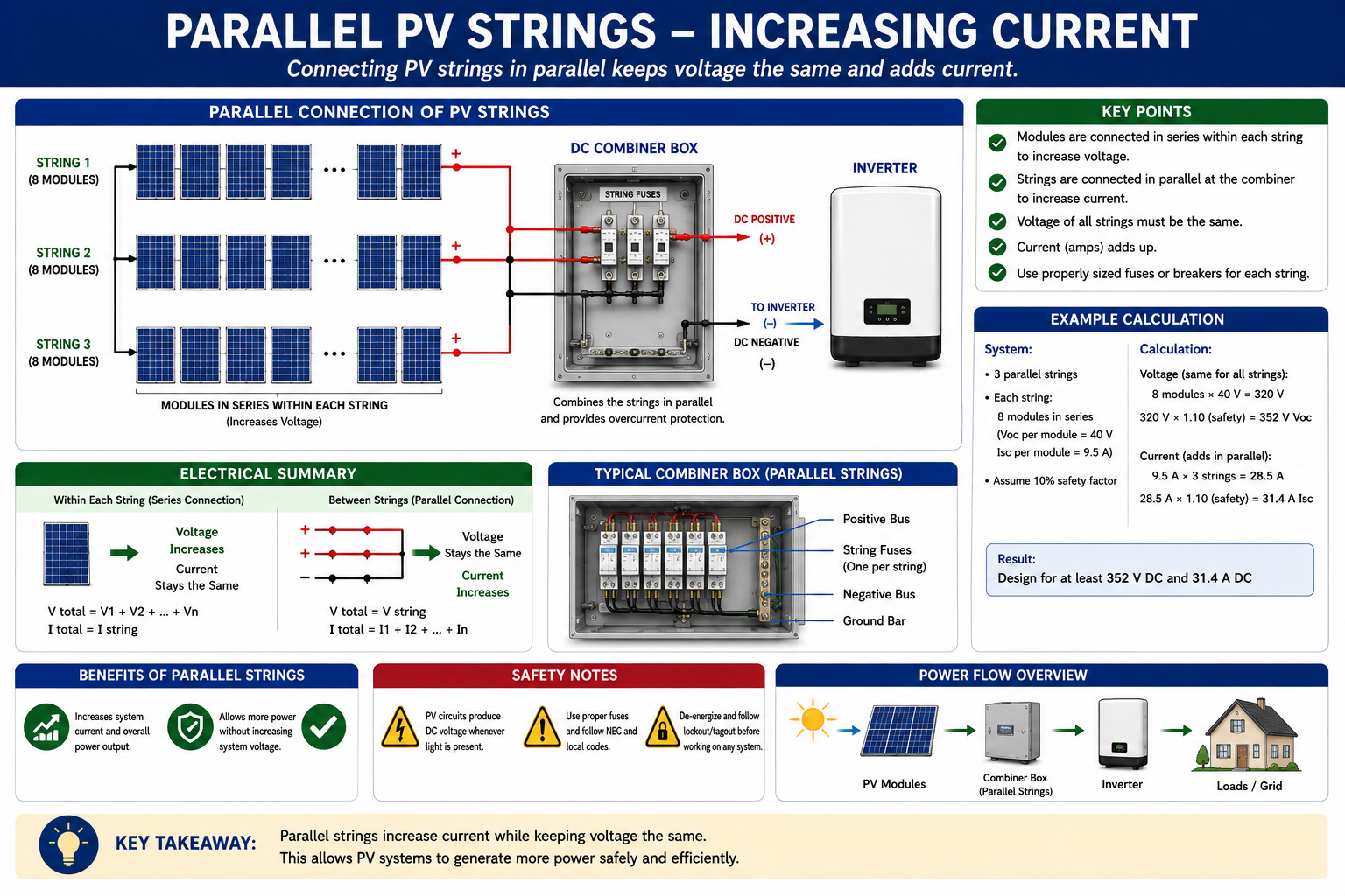
Three Similar Strings in Parallel
If three strings are each producing approximately 8 amps under comparable operating conditions, their combined current could be approximately 24 amps at the common output.
8 A + 8 A + 8 A ≈ 24 A
Actual field readings may differ because irradiance, orientation, shading, temperature, module condition, and other operating factors can affect each string.
The Physical Array and Electrical Circuits Are Not Always the Same Thing
A PV array is the collection of photovoltaic modules associated with an installation or a defined portion of the installation. One physical group of modules can contain several electrically separate strings.
Do not assume that every module visible on the same roof surface belongs to one electrical circuit. Different groups may feed separate inverter inputs, separate MPPT channels, different inverters, or different module-level power-electronics circuits.
Field point: Follow the electrical configuration rather than relying only on the physical appearance of the array. System documentation, conductor routing, inverter inputs, combiner equipment, and monitoring information help identify how the modules are actually grouped.
Similar Strings Provide a Built-In Comparison
When two or more strings use the same module type, contain the same number of modules, face a similar direction, and receive similar sunlight, their electrical behavior should generally be reasonably similar.
This gives the technician a powerful comparison tool. If three comparable strings behave normally and one differs significantly, the investigation can be concentrated on the abnormal string instead of beginning with the entire array.
A Shaded Module Can Affect More Than One Cell
PV output depends on solar energy reaching the cells. When part of a module is shaded, the affected cells cannot contribute electrical energy at the same level as fully illuminated cells.
In a conventional series string, the operating condition of one module can affect the performance of the electrically related string. Module-level power electronics can change how strongly one module affects neighboring modules, but shading still reduces the energy available from the shaded module itself.
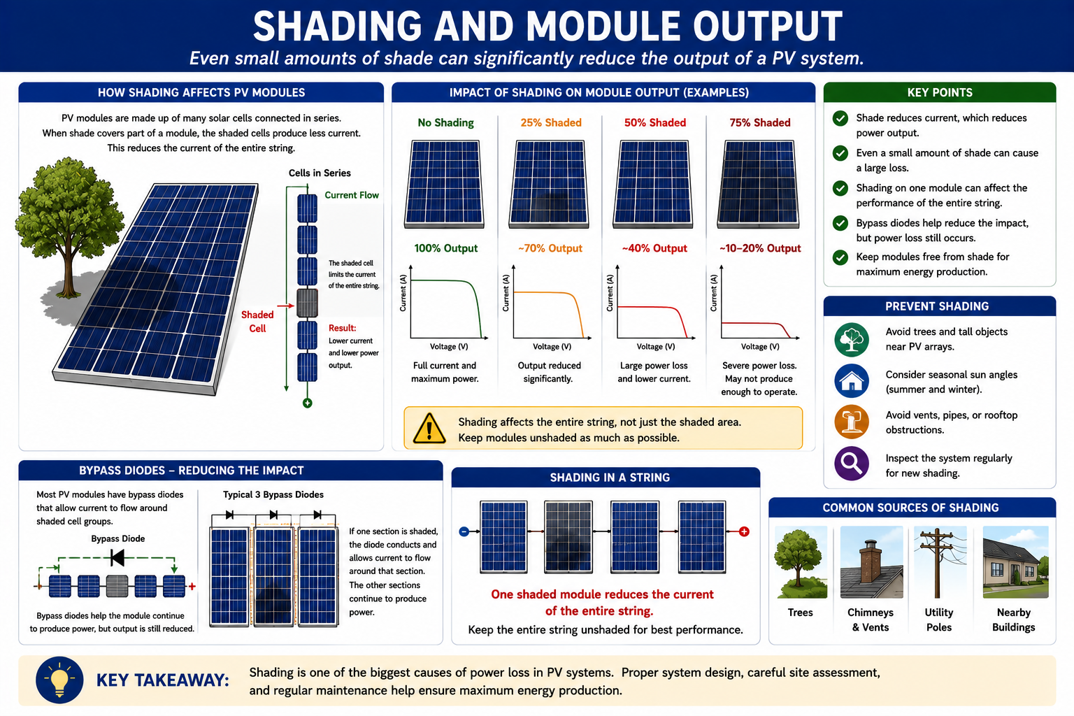
Trees and Vegetation
Growing vegetation can create new shading that was not present when the PV system was originally installed.
Roof Structures
Chimneys, vents, antennas, parapets, adjacent roof sections, and other structures can create predictable shading at certain times of day.
Debris and Contamination
Leaves, bird deposits, dirt, snow, and other material can reduce the solar energy reaching part of a module.
Module-Level Electronics
Optimizers and microinverters can reduce the influence of one poorly performing module on unrelated modules, but they cannot restore sunlight that is not reaching the shaded module.
Current Measurements Need Similar Solar Conditions
PV current responds strongly to available irradiance. This makes current comparison useful, but only when the circuits being compared are experiencing reasonably similar conditions.
A string in full sun should not automatically be expected to produce the same current as a string receiving partial shade. Likewise, an east-facing string and west-facing string may behave differently at the same time of day even when both are functioning correctly.
Compare Similar Circuits
Use strings with the same module type, similar module count, orientation, and electrical configuration whenever possible.
Check the Sunlight
Confirm that changing cloud cover, moving shade, or other environmental conditions are not creating the difference.
Look for a Large Difference
Small differences may be normal. A substantial unexplained difference between otherwise comparable strings deserves further investigation.
Use the Series and Parallel Relationships to Interpret Problems
Zero String Voltage
An open circuit, disconnected conductor, open device, damaged connection, incorrect test point, or another interruption may prevent expected string voltage from reaching the measurement point.
Unexpectedly Low Voltage
Investigate module count, circuit configuration, connections, bypassed portions of modules, equipment state, and other conditions that can reduce the expected voltage.
Normal Voltage but Low Production
Sunlight, shading, current limitation, module condition, inverter operation, wiring resistance, or another performance issue may be involved.
One String Differs From Others
When comparable strings operate normally and one does not, the abnormal string becomes the logical area for the next inspection or measurement.
PV String Current Is Direct Current
PV string conductors carry DC current. A clamp meter designed only for AC amperage will not correctly measure DC string current.
When DC current measurement is required, use a meter or clamp meter specifically capable of measuring DC amperage and properly rated for the expected circuit conditions. Detailed PV electrical-testing procedures are covered in Part III.
Series Strings Can Produce Hazardous DC Voltage
The voltage of series-connected PV modules adds together. A string containing many modules can therefore produce substantial DC voltage whenever sufficient light reaches the array, even when the inverter is shut down or the AC circuit is disconnected.
Do not assume that opening an AC breaker eliminates DC voltage from the array. Identify the system configuration and available energy sources, follow manufacturer procedures, use appropriately rated test equipment and PPE, and follow applicable electrical and workplace-safety requirements.
What You Should Take From This Lesson
Modules Are the Building Blocks
Individual photovoltaic modules provide the basic DC generating source used to construct larger PV circuits and arrays.
Series Connections Add Voltage
Modules connected in series form strings, and the individual module voltage contributions combine to create the total string voltage.
Parallel Connections Add Current
Comparable strings connected in parallel operate at approximately the same voltage while their available currents combine.
Nameplate Information Establishes Expectations
Module voltage, current, power, and system ratings provide the reference needed to evaluate module and string measurements.
Shading Changes Output
Shading reduces the electrical contribution of affected modules and can influence the performance of the associated string or module-level circuit.
String Comparison Is a Diagnostic Tool
When similar strings operate under similar conditions, significant differences in voltage or current can help localize a problem.
String Inverters, Microinverters, and Power Optimizers
The next lesson examines the major power-conversion architectures encountered in PV systems. Understanding where DC-to-AC conversion occurs and whether module-level power electronics are present is essential for choosing the correct troubleshooting path.
PV Solar System Fundamentals
Return to the Part I landing page for all six PV Solar System Fundamentals lessons.