String Inverters, Microinverters, and Power Optimizers
PV modules generate DC electricity, but most building electrical systems use AC electricity. The inverter architecture determines where that DC-to-AC conversion occurs, how modules are electrically grouped, what conductors are present throughout the installation, and which test points are useful during troubleshooting.
This lesson compares conventional string-inverter systems, microinverter systems, and string-inverter systems using power optimizers. The goal is not to choose or design a system. The goal is to recognize what is installed and understand how the equipment arrangement changes the technician’s inspection and diagnostic path.
Find Out Where the Power Conversion Happens
One of the first questions a technician should answer when approaching a PV installation is where the DC generated by the modules becomes AC. The answer immediately provides information about the wiring, equipment locations, monitoring capabilities, likely test points, and electrical hazards present in different portions of the system.
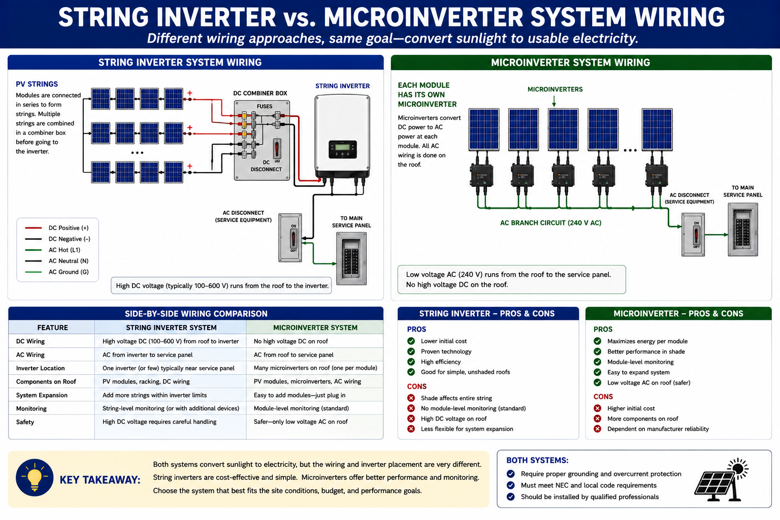
A conventional string-inverter system sends the combined DC output of a group of modules to a centralized inverter. A microinverter system converts the output of individual modules to AC at or near the array. A power-optimizer system performs module-level DC-to-DC power conversion but still sends DC through a string to a central inverter for final conversion to AC.
DC In — AC Out
The fundamental inverter function is to convert DC electrical power from photovoltaic generation into AC electrical power suitable for the electrical system the inverter serves. Modern inverters also commonly perform monitoring, protective, communications, maximum-power-point tracking, and grid-interconnection functions.
For troubleshooting purposes, think of the inverter as a boundary between electrical sections of the PV system. On one side is PV-generated DC power. On the other side is AC power connected to building distribution equipment, loads, or the utility interconnection.
DC Input
The inverter receives energy generated by the PV modules from one or more strings or through compatible module-level equipment.
Power Conversion
Power electronics inside the inverter convert DC electricity into controlled AC electricity.
AC Output
The inverter supplies AC power through the appropriate distribution, disconnecting, protection, and interconnection equipment.
Monitoring & Protection
The inverter may report operating information, record faults, communicate with other equipment, and respond to abnormal AC or DC conditions.
Several Modules Feed a Central Inverter
In a conventional string-inverter system, modules are connected in series into one or more DC strings. Those strings are connected to a string inverter either directly or through additional combining, disconnecting, or protective equipment depending on the installation.
The centralized inverter performs the DC-to-AC conversion for the connected string or strings. This means significant portions of the wiring between the array and inverter remain DC circuits.
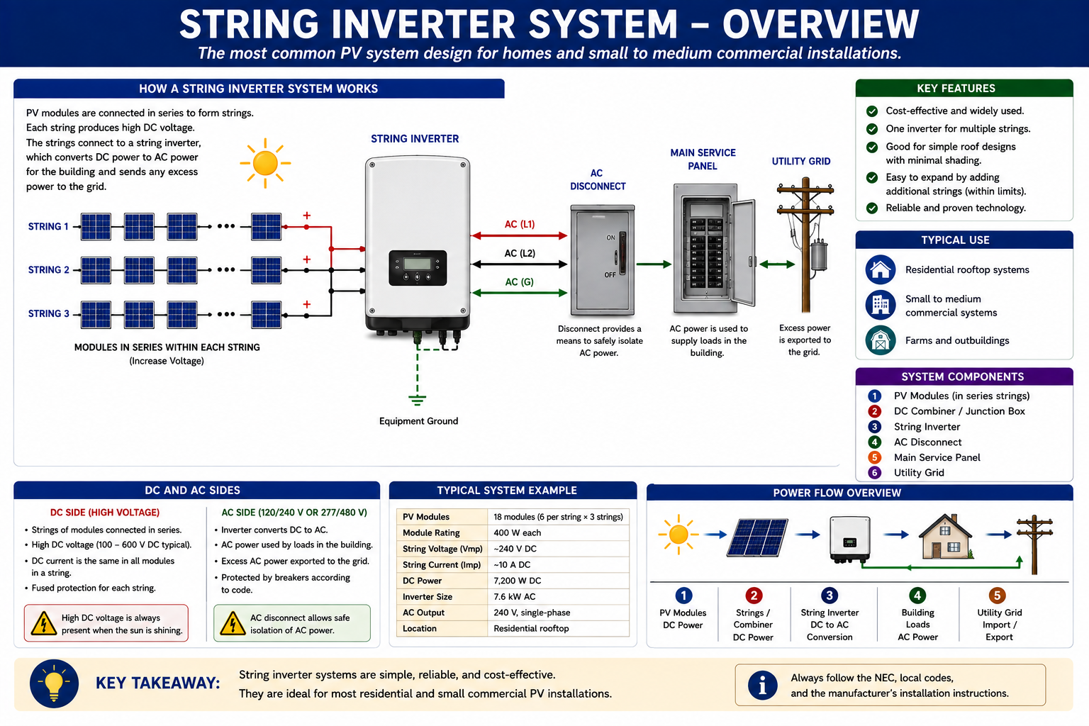
PV Modules Generate DC
Each illuminated module contributes electrical power to the series string.
Modules Form a String
Series-connected modules create the string voltage discussed in Lesson 3.
DC Travels to the Inverter
String conductors carry PV-generated DC power from the array toward the inverter or associated DC equipment.
The Inverter Produces AC
The centralized inverter converts the combined DC input into AC power for the electrical system.
The String Gives the Technician Useful Test Points
Because modules are connected together before reaching the inverter, a technician can often compare complete strings before moving to individual modules. String voltage, string current, inverter input data, monitoring information, and comparison with other similar strings can quickly narrow a problem to one portion of the array.
This is why Part III of this course tests the broader electrical circuit before moving to individual modules. If three strings behave normally and one is significantly different under comparable conditions, the investigation can be concentrated on that string.
The Inverter Adjusts Its Operating Point
A PV module does not produce one fixed combination of voltage and current. Its operating characteristics change with sunlight, temperature, loading, shading, and other conditions. Maximum power point tracking, commonly abbreviated MPPT, is the power-electronic process used to operate PV generation near the combination of voltage and current that produces the most useful power under current conditions.
With a traditional string inverter, one inverter input may manage the operating point of an entire string or group of strings. Module-level power electronics move some of that optimization closer to each individual module.
DC-to-AC Conversion Occurs at the Module
A microinverter is a small inverter installed at or near a PV module. Instead of sending the module’s DC output through a long string circuit to a central inverter, the module connects to a microinverter and the DC-to-AC conversion occurs at the array.
The AC outputs from multiple microinverters are then interconnected through an AC branch-circuit arrangement. This changes the technician’s electrical path substantially: the longer conductors leaving the array are AC rather than the traditional high-voltage DC string conductors found in a conventional string-inverter system.
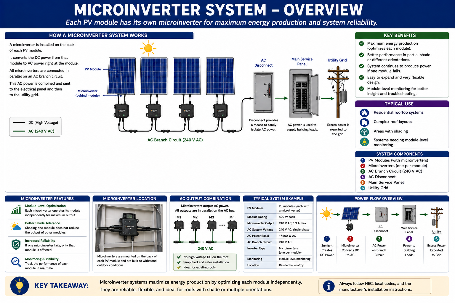
Module-Level Conversion
The DC output of each module, or module grouping supported by the equipment, is converted to AC locally.
Independent Operation
Individual module-level conversion reduces the degree to which one module’s operating condition determines the power available from unrelated modules.
AC Branch Circuit
The outputs of the microinverters are combined electrically on compatible AC branch-circuit equipment rather than as a conventional DC string feeding one central inverter.
Module-Level Information
Many microinverter platforms provide monitoring that allows production and status information to be viewed at the individual-device or individual-module level.
One Poor Module Does Not Automatically Mean the Entire Array Is Poor
Module-level conversion gives the technician a different troubleshooting advantage. Monitoring information may identify one module or microinverter that is producing less than neighboring units while the remainder of the array continues operating normally.
The technician can then concentrate on the affected module, microinverter, DC connection between them, AC branch connection, communications path, environmental condition, or other local problem rather than beginning with the entire array.
Diagnostic point: If nineteen microinverters report normally and one does not, start by determining what is different about the affected location instead of treating the entire PV system as failed.
Module-Level DC Conversion With a Central Inverter
A DC power optimizer is module-level power electronics installed with a PV module. Unlike a microinverter, the optimizer does not normally provide the final AC output for the building. It performs DC-to-DC power conversion and optimization at the module level while the modules and optimizers remain part of a DC system feeding a compatible string inverter.
This architecture combines module-level control and monitoring capabilities with centralized DC-to-AC conversion. From a service perspective, it also adds another electronic device between the PV module and the central inverter.
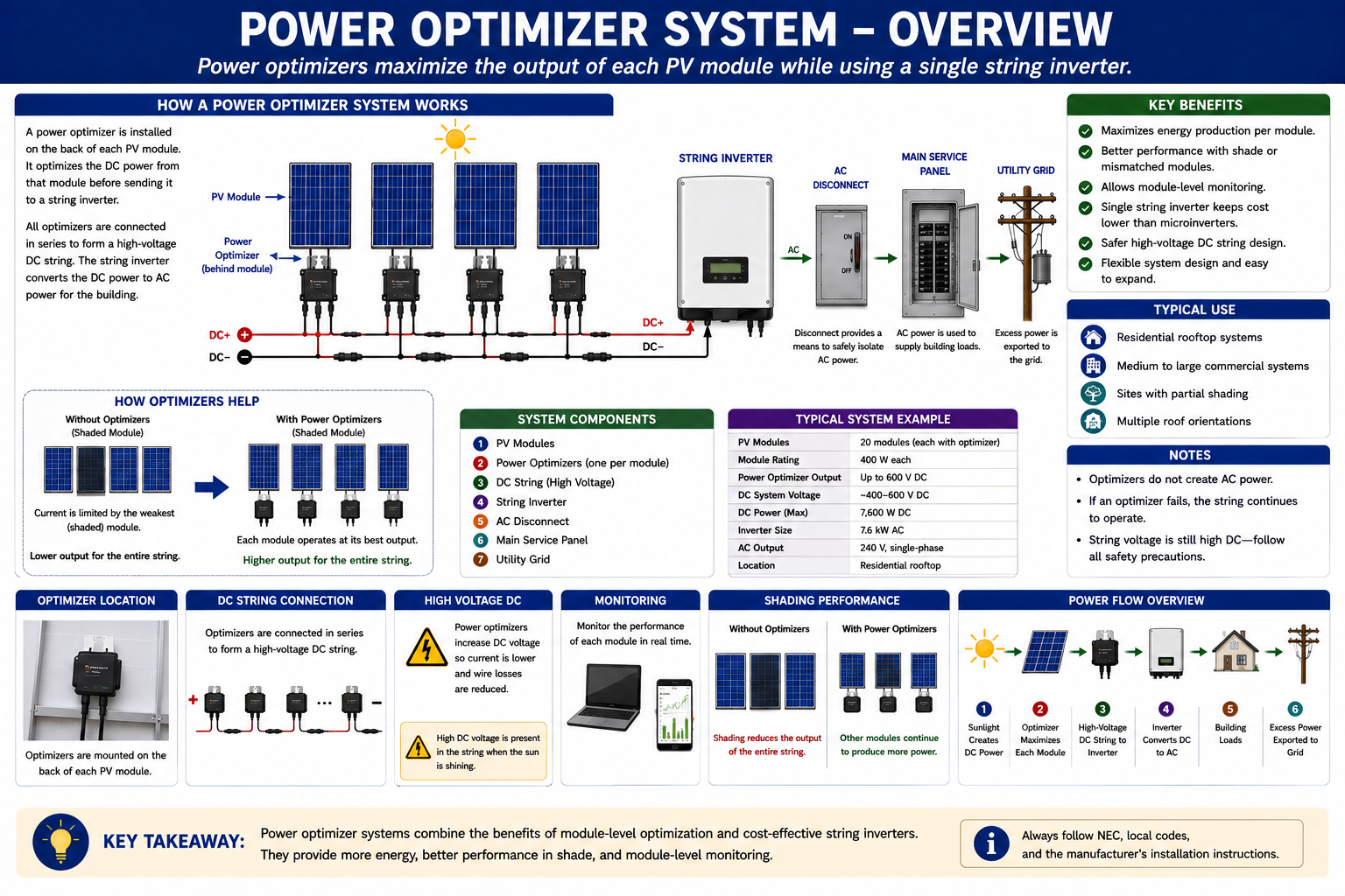
Separate the Module From the Optimizer in Your Diagnosis
When an optimizer-equipped module appears to underperform, do not immediately assume that the PV module itself has failed. The module, optimizer, connectors, conductors, inverter input, monitoring system, and other related equipment can all contribute to the reported condition.
Later electrical-testing lessons use this distinction deliberately. If the module itself produces reasonable electrical values but the system reports abnormal performance when the optimizer is part of the circuit, the evidence begins to point away from the module and toward the optimizer or another portion of the system.
Microinverters and Optimizers Are Both MLPE — But They Do Different Jobs
Microinverters and DC power optimizers are commonly grouped under the term module-level power electronics, or MLPE. Their major field-service characteristic is that some of the power conversion, optimization, monitoring, or control occurs at the individual-module level rather than only at one central inverter.
The important technician distinction is that a microinverter performs DC-to-AC conversion at the module, while a power optimizer performs DC-to-DC conversion and still relies on a compatible central inverter for the final AC output.
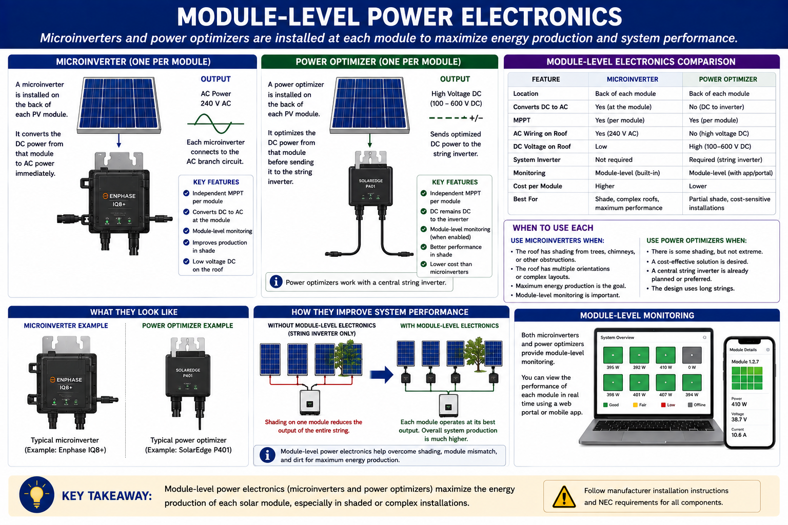
Traditional String Inverter
Modules form DC strings and a centralized inverter performs the DC-to-AC conversion.
Microinverter
DC-to-AC conversion occurs at or near individual modules and the array-side collection circuit is AC.
Power Optimizer
Module-level DC-to-DC power electronics feed a compatible DC string and centralized inverter.
Monitoring
MLPE systems frequently provide more detailed module-level operating information than a basic conventional string-inverter arrangement.
Architecture Changes How Module Differences Affect Production
In a conventional series string, module operating conditions are electrically related. Shading, damage, orientation differences, contamination, aging, or other mismatch conditions affecting one module can influence the performance of the string.
Module-level power electronics allow each associated module to be controlled more independently. This does not eliminate losses caused by shading or a damaged module—the affected module cannot produce energy that is not available—but it can reduce the effect that the weak module has on otherwise productive modules.
Look Under the Modules
The inverter architecture may be obvious from equipment mounted near the electrical service, but sometimes the most important components are under the array. A rooftop installation with a central inverter may still contain power optimizers beneath every module. A system without a large central PV inverter may use microinverters mounted under the modules.
Use equipment labels, conductor paths, monitoring information, system documentation, and a safe visual inspection to determine what is actually installed before deciding how the system should be tested.
What Changes for the Technician?
String Inverter
Expect series-connected modules, DC string conductors leading toward centralized conversion equipment, and useful string-level electrical measurements.
Microinverters
Expect module-level DC-to-AC conversion, AC collection from the array, multiple electronic devices at the modules, and often detailed module-level monitoring.
Power Optimizers
Expect module-level DC electronics combined with DC string wiring and a compatible centralized inverter.
Choose the Diagnostic Path
Use the architecture to determine whether the next useful information is at the AC branch circuit, central inverter, DC string, optimizer, microinverter, module, connector, or monitoring system.
The Architecture Determines What Type of Circuit Leaves the Array
For a conventional string-inverter system, the principal power conductors leaving the array toward the inverter are DC. For a microinverter system, DC-to-AC conversion occurs at the module level and the collection wiring leaving the array is AC.
Power-optimizer systems fall between these two arrangements: module-level electronics are present, but the downstream string remains DC until it reaches the compatible central inverter.
Use Monitoring Data as Evidence
Modern PV systems frequently provide production data, operating status, alarms, historical graphs, and communications information. The level of detail depends on the equipment architecture and manufacturer.
A centralized inverter may provide aggregate inverter or string information, while MLPE platforms may provide individual-module or individual-device information. Monitoring can help identify where to investigate, but it does not replace physical inspection or electrical testing when those steps are necessary.
Technician rule: A monitoring alarm tells you where the system detected a problem. It does not automatically prove which physical component caused the problem.
The Architecture Determines How Much of the System Is Affected
Central Inverter Failure
If one centralized inverter serves a large portion of the array, loss of that inverter can stop production from all PV circuits connected to it.
One Microinverter Failure
A failure associated with one microinverter will normally affect the module or module grouping served by that device rather than stopping every other independent microinverter.
Optimizer Failure
An optimizer fault may affect the associated module and can also influence string operation depending on the equipment architecture and nature of the failure.
Communications Failure
Loss of monitoring or communications does not always mean that power conversion has stopped. Verify electrical operation independently when necessary.
Do Not Assume the Same Shutdown Condition for Every Architecture
String inverters, microinverters, optimizers, rapid-shutdown equipment, battery systems, and hybrid systems can create very different energized conditions. Turning off an AC breaker or operating one disconnect does not automatically establish that every PV conductor is de-energized.
Identify the architecture and all available energy sources before service. Follow manufacturer shutdown and startup procedures, equipment labeling, applicable electrical requirements, workplace-safety practices, lockout/tagout procedures where applicable, and required PPE.
What You Should Take From This Lesson
Find the DC-to-AC Conversion Point
Where conversion occurs is one of the fastest ways to distinguish a conventional string-inverter system from a microinverter system.
String Inverters Use Centralized Conversion
Modules form DC strings that feed one or more centralized inverters.
Microinverters Convert Power at the Array
Module-level inverters convert DC to AC locally and their AC outputs are interconnected through compatible branch-circuit equipment.
Optimizers Keep the Main Power Path DC
Power optimizers perform module-level DC-to-DC conversion while a central inverter still performs the system’s final DC-to-AC conversion.
Architecture Determines the Troubleshooting Path
Knowing what equipment is installed tells the technician where useful AC, DC, string-level, module-level, monitoring, and communications information can be obtained.
PV System Components and Power Flow
The next lesson moves beyond inverter architecture and follows the complete electrical path through the installation. It identifies disconnects, combiner equipment, conductors, distribution equipment, service connections, and the path PV-generated power follows from the array into the building electrical system.
PV Solar System Fundamentals
Return to the Part I landing page for all six PV Solar System Fundamentals lessons.