Pressure-Switch Troubleshooting
A pressure switch that is open may be operating correctly, responding to the wrong sensed pressure, incorrectly adjusted, miswired, or internally defective. Troubleshooting must determine which condition exists before the control is reset, adjusted, bypassed, or replaced.
The most reliable method compares four things at the same moment: actual system pressure, pressure at the switch connection, expected contact state, and measured electrical state. When those facts agree, the diagnosis becomes much clearer.
What You Will Learn
By the end of this lesson you should be able to:
Classify the pressure-switch complaint.
Separate a system-pressure problem from sensing, adjustment, wiring, and switch problems.
Diagnose low-pressure trips.
Evaluate refrigerant feed, evaporator load, airflow, valve position, and pump-down operation.
Diagnose high-pressure trips.
Evaluate condenser heat rejection, refrigerant conditions, restrictions, and valve positions.
Inspect the sensing path.
Recognize leaks, restrictions, trapped pressure, damage, and connection-location errors.
Prove contact operation.
Compare measured pressure with continuity, resistance, voltage drop, and reset behavior.
Use a systematic diagnostic process.
Verify the repair through repeated operation without defeating the control’s safety function.
Should the Switch Be Open?
Do not begin by assuming that the pressure switch failed. Begin by determining the pressure acting on the control and whether that pressure should place the selected contact path open or closed.
Actual System Pressure
Measure pressure with appropriate instruments at a location that represents the condition being diagnosed.
Pressure at the Switch
Confirm that the sensing line, fittings, valves, and connection allow the same condition to reach the control.
Expected Contact State
Use switch action, cut-in, cut-out, differential, reset method, and the selected terminal path.
Measured Electrical State
Use safe continuity, resistance, or voltage testing to determine whether the contacts are actually open or closed.
If system pressure reached the specified cut-out and the contacts opened correctly, diagnose the condition that caused the pressure event. Replacing the switch will not correct the refrigeration, airflow, waterflow, valve, load, or control-sequence problem.
Why Suction Pressure Falls
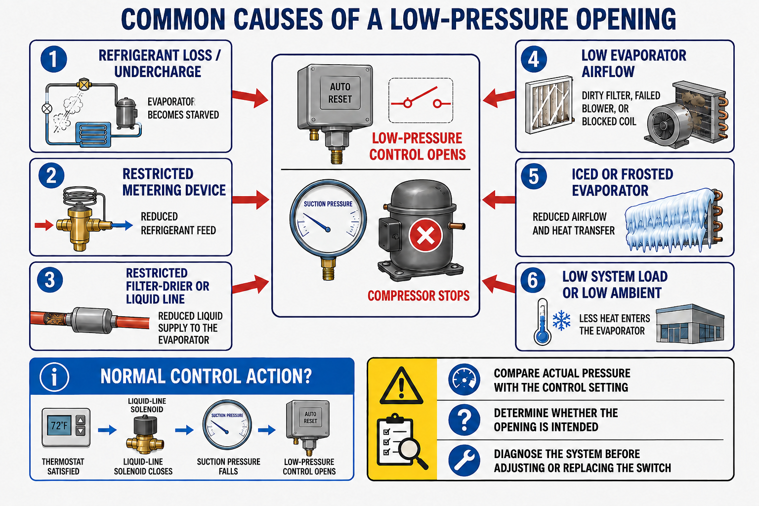
Refrigerant Loss
A leak and resulting undercharge can reduce evaporator feed and lower suction pressure.
Restricted Refrigerant Feed
A restricted filter-drier, metering device, liquid line, solenoid valve, distributor, or other component can starve the evaporator.
Low Evaporator Airflow
A dirty filter, blocked coil, failed fan, incorrect blower speed, closed damper, or duct restriction can reduce evaporator load.
Evaporator Ice
Ice restricts heat transfer and airflow and may drive suction pressure lower as the condition worsens.
Low Product or Water Load
Low temperature, inadequate flow, or very little heat entering the evaporator can reduce suction pressure.
Closed or Partially Closed Valve
A service valve, hand valve, liquid-line solenoid, or other valve in the wrong position can restrict refrigerant flow.
In a pump-down system, the thermostat closes the liquid-line solenoid when demand ends, suction pressure falls, and the low-pressure switch intentionally stops the compressor. Confirm whether the opening occurred during normal sequencing or during an active cooling demand.
Why Condensing Pressure Rises
Dirty or Blocked Condenser
Dirt, debris, bent fins, scale, blocked air paths, or poor coil maintenance can reduce heat rejection.
Fan or Waterflow Failure
A failed fan, wrong rotation, incorrect speed, pump problem, closed water valve, fouling, or warm entering water can raise condensing pressure.
Hot-Air Recirculation
Condenser discharge air returning to the inlet raises entering-air temperature and reduces heat-rejection capacity.
Refrigerant Overcharge
Excess refrigerant can occupy condenser volume and contribute to elevated liquid level and high-side pressure.
Noncondensables
Air or another noncondensable gas adds partial pressure and can cause pressure to be high for the measured condenser-medium temperature.
Restriction or Closed Valve
A closed discharge or liquid valve, crushed line, or severe restriction can create excessive pressure upstream of the blockage.
High-side pressure often falls after the compressor stops. A dirty condenser, failed fan, closed valve, overcharge, or other cause can still be present and can immediately recreate the trip after restart.
Diagnose in a Deliberate Order
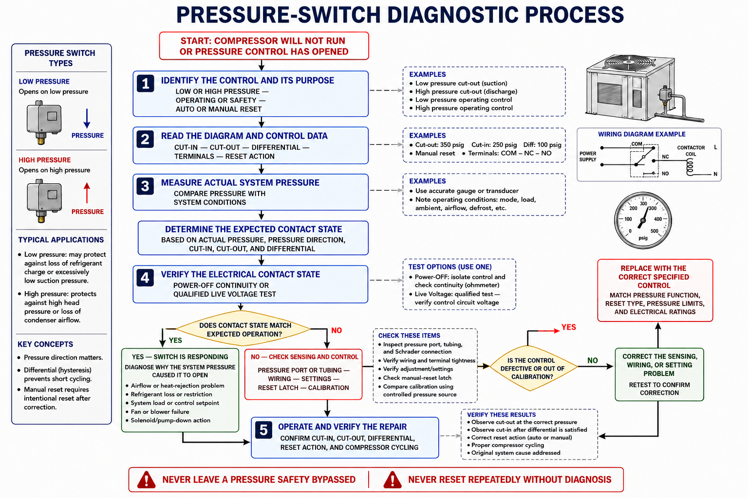
1. Identify the Function
Determine whether the control provides low-pressure operating control, pump-down, high-pressure protection, fan cycling, alarm input, or another function.
2. Identify the Control
Record the model, range, switch action, contact arrangement, reset method, pressure connection, and electrical rating.
3. Confirm the Sequence
Use the equipment diagram and sequence of operation to determine when the contacts should change state.
4. Measure Pressure
Observe pressure before, during, and after the trip rather than relying only on a reading taken after shutdown.
5. Check the Sensing Path
Verify that the pressure acting on the switch matches the condition measured by the technician.
6. Verify Settings and Reset
Compare the indicated and calculated cut-in, cut-out, differential, and reset condition with the required values.
7. Test the Circuit
Check terminal identification, wiring, continuity, resistance, and voltage drop using safe procedures.
8. Verify the Repair
Operate the equipment through repeated cycles and confirm correct pressure, contact action, and complete system performance.
The Switch and Gauge May See Different Pressures
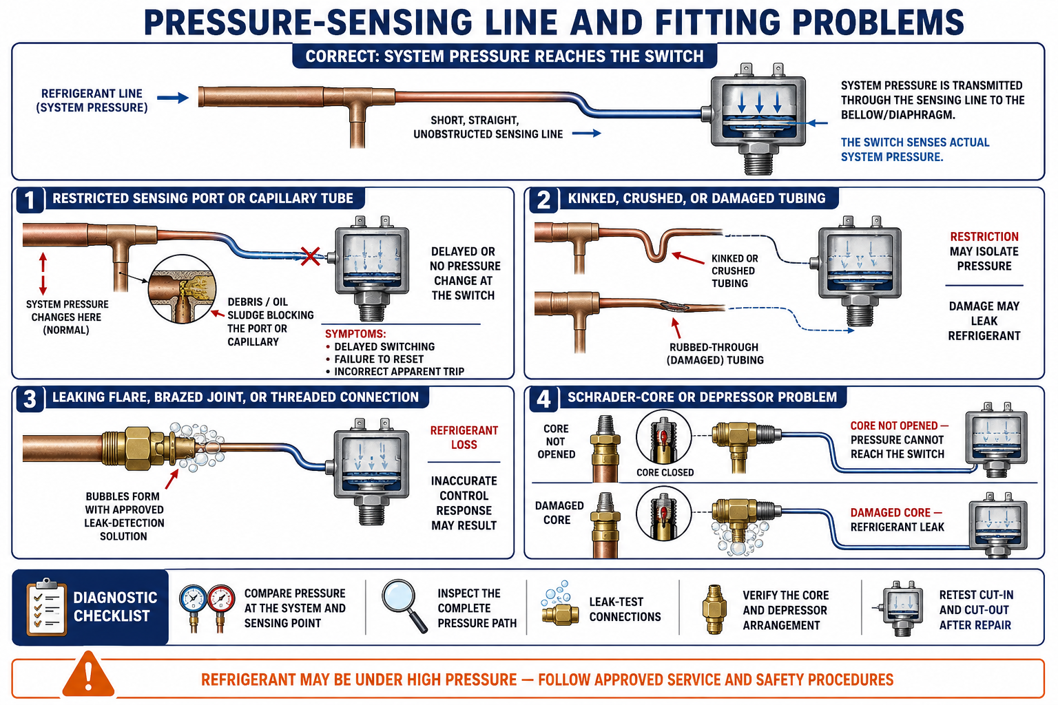
Kinked or Crushed Capillary
A damaged tube can restrict pressure transmission and delay or prevent the control from responding.
Restricted Fitting or Passage
Debris, sealant, oil, liquid, corrosion, or a damaged fitting can obstruct the pressure path.
Leaking Connection
A leak can change the pressure acting on the control and also release refrigerant.
Closed Service Valve
A valve can isolate the switch or gauge and trap a pressure that no longer represents the operating system.
Trapped Liquid or Oil
Improper tap location, routing, or mounting can allow material to accumulate in the sensing path and affect response.
Different Test Location
Pressure drop across piping, valves, restrictions, or operating components can make a remote gauge reading differ from the switch connection.
Pressure can equalize rapidly after the compressor stops. Record the pressure and contact event as the trip occurs whenever the equipment and safe test procedure allow it.
Incorrect Adjustment Can Imitate a System Fault
Unwanted Shutdown
The control can open during otherwise acceptable operation if cut-out is set inside the normal operating range.
Delayed or Rapid Restart
An unsuitable cut-in or differential can prevent restart, create an excessive swing, or contribute to short cycling.
Confirm what each scale displays. RANGE may indicate cut-in, cut-out, or move both points. DIFF may move the low event or high event depending on the model. A manual-reset control uses a specified reset condition rather than an automatic cut-in relationship.
Changing the pressure setting to prevent a trip can remove intended protection or allow operation outside equipment limits. Compare measured operation with the original equipment specification before making any adjustment.
The Pressure Mechanism May Be Correct While the Circuit Is Not
Wrong SPDT Terminal
Using the normally open path instead of the normally closed path can reverse the intended equipment sequence.
Loose or Corroded Connection
A poor terminal can create intermittent operation, heat, arcing, and voltage drop that appears to be an internal switch problem.
Damaged Conductor
A broken wire, failed splice, damaged insulation, or poor connector can open the circuit independently of the switch contacts.
Parallel Path or Backfeed
Connected controls, alarms, boards, or loads can create misleading continuity and voltage readings.
Worn or Pitted Contacts
Contacts may close mechanically but develop excessive resistance and voltage drop under load.
Welded Contacts
Damaged contacts may remain electrically closed when pressure should open the controlled circuit.
Prove Failure Against Specifications
Incorrect Operating Pressure
The contacts consistently change state outside the permitted cut-in or cut-out tolerance when pressure is measured correctly.
No Contact Transfer
Pressure crosses the specified operating point, but the isolated contact paths do not open, close, or transfer as designed.
Will Not Reset
The required pressure condition is satisfied and the proper reset procedure is followed, but the control remains locked out.
Excessive Contact Resistance
The closed contact path has abnormal resistance or voltage drop after wiring and terminal conditions are verified.
Pressure-Sensing Failure
The bellows, diaphragm, capillary, fitting, or seal is damaged or leaking and cannot respond correctly.
Unstable or Nonrepeatable Action
The contact events vary beyond permitted tolerance over repeated controlled cycles.
Recheck meter setup, pressure location, scale interpretation, switch terminals, wiring isolation, valve position, and repeatability before declaring the control defective.
The Safety Function Must Remain Intact
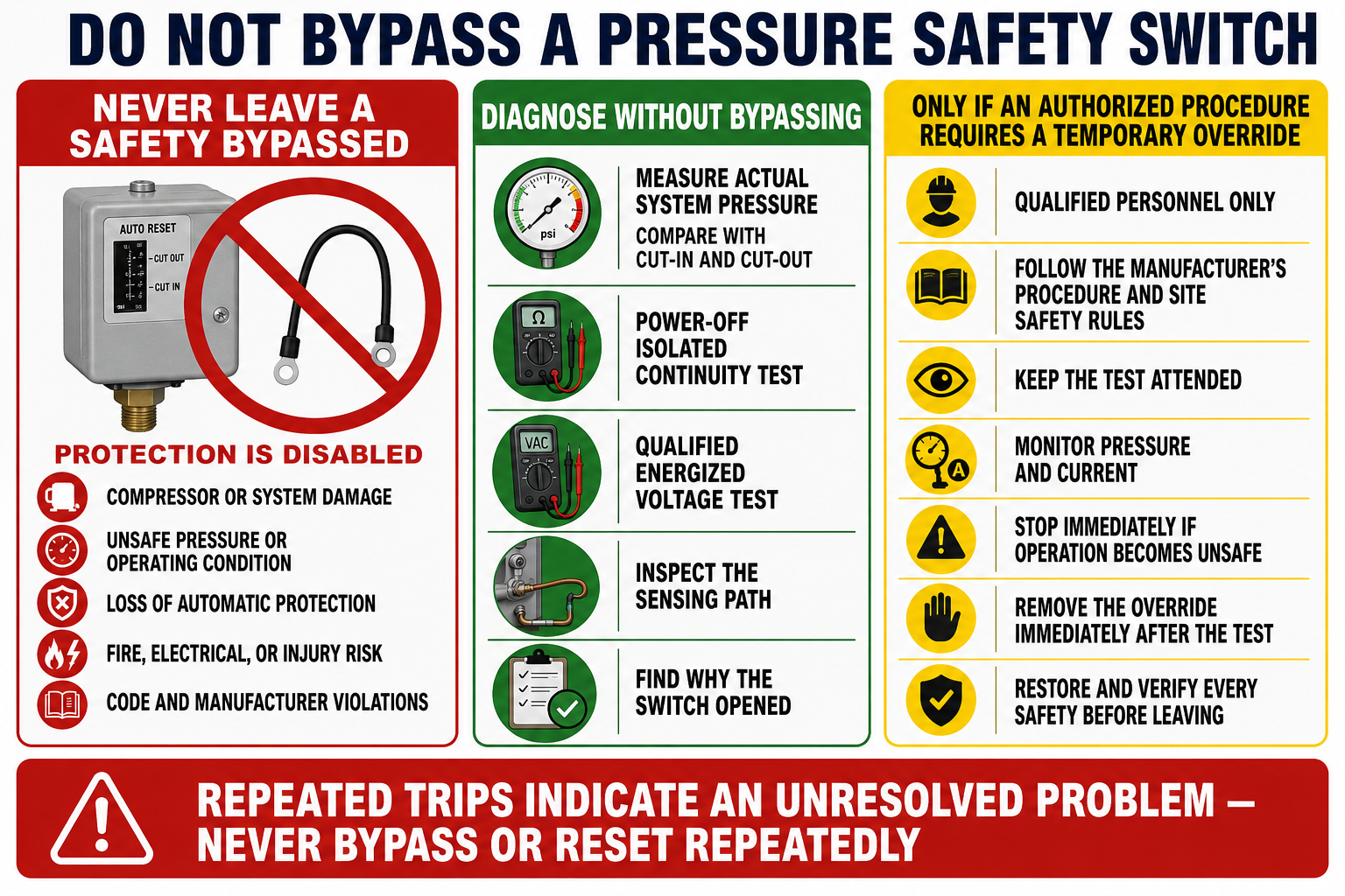
A jumper across a pressure switch makes the circuit behave as though the selected contact path is closed regardless of system pressure. It does not prove why the switch opened and does not correct the condition that caused the trip.
Control-circuit devices and interlocks are not substitutes for disconnecting and controlling hazardous energy. Follow the employer’s electrical and lockout/tagout procedures for servicing, and never leave a pressure safety defeated when returning equipment to service.
Temporary diagnostic actions: Any temporary jumper or forced operation must be specifically permitted by applicable manufacturer and workplace procedures, performed by a qualified person who maintains control of the equipment, and removed immediately after the authorized test.
Capture the Condition as It Happens
Intermittent problems often disappear after shutdown because pressures equalize, temperatures change, ice melts, fans restart, connections cool, or a manual-reset switch has already been reset. Collecting time-related evidence is essential.
Record Operating Pressures
Monitor low-side and high-side pressure before and at the moment of the trip when safe and appropriate.
Record Temperatures
Measure condenser entering and leaving conditions, suction and liquid lines, air or water streams, and ambient conditions as required.
Observe Loads and Components
Watch fan operation, valve position, solenoid action, airflow, waterflow, contactors, and controller commands.
Use Available History
Review fault codes, event logs, trend data, prior service notes, weather, load changes, and reports from operators.
When conditions are safe, record the tripped contact state, actual pressures, control settings, and visible system condition before resetting a manual control. Resetting can erase the most useful diagnostic evidence.
Test the Complete Operating Sequence
- Correct the confirmed refrigeration, airflow, waterflow, valve, sensing, adjustment, wiring, or switch problem.
- Restore all conductors, fittings, valves, covers, insulation, locks, adjustment locks, and protective devices.
- Confirm the control uses the correct settings and reset method for the equipment.
- Operate the system through the number of cycles required by the manufacturer.
- Measure actual cut-in and cut-out or trip and reset conditions.
- Confirm normal pressures, saturation temperatures, line temperatures, airflow or waterflow, and load response.
- Verify that alarms, controllers, contactors, solenoids, fans, and the compressor follow the intended sequence.
- Document the original complaint, measurements, diagnosis, repair, final settings, and verified operating results.
Successful restart proves only that the circuit can operate at that moment. A complete verification confirms that the pressure switch protects and controls the system correctly through changing pressure and repeated operation.
Avoid These Troubleshooting Errors
“An open pressure switch is defective.”
An open switch may be correctly responding to its cut-out pressure or remaining in a required manual-reset lockout.
“Low suction pressure always means low refrigerant.”
Low charge is one possibility, but restricted feed, low evaporator load, poor airflow, icing, and valve position can produce similar pressure.
“Pressure at my gauge is pressure at the switch.”
Different locations, closed valves, restrictions, trapped pressure, and sensing-line defects can create different readings.
“If a jumper starts the unit, the switch is bad.”
The jumper only closes the electrical path. It does not show whether the switch opened correctly because of system pressure.
Can You Separate Switch Failure From System Failure?
- What four facts should be compared when diagnosing a pressure switch?
- Why should an open pressure switch not automatically be replaced?
- Name four conditions that can cause a low-pressure trip.
- How does normal pump-down differ from an unexpected low-pressure trip?
- Name four conditions that can cause a high-pressure trip.
- Why can a fault still exist after high-side pressure falls?
- How can a restricted sensing line affect switch operation?
- Why should pressure be recorded as the trip occurs?
- How can incorrect settings imitate a system problem?
- What evidence can prove that the switch itself is defective?
- Why does a jumper not prove pressure-switch failure?
- What must be verified before the equipment is returned to service?
What You Should Have Learned
Troubleshooting begins by determining whether measured pressure should place the selected contact path open or closed.
Low-pressure trips can result from refrigerant starvation, low evaporator load, airflow problems, icing, valve position, or normal pump-down.
High-pressure trips can result from poor condenser heat rejection, overcharge, noncondensables, restrictions, closed valves, or excessive load.
Sensing-line restrictions, leaks, damage, trapped pressure, and different test locations can make the switch and gauge see different conditions.
Incorrect settings, wrong terminals, loose wiring, parallel paths, damaged contacts, and backfeed can imitate switch failure.
Actual switch failure is proven by comparing repeatable measured pressure and electrical operation with the exact specifications.
A pressure safety must never be permanently bypassed, and a control circuit is not an energy-isolating device.
A completed repair is verified through repeated cycles with correct pressure, contact action, and complete system operation.