Pressure-Switch Electrical Testing
Electrical testing can show whether a pressure switch contact path is open, closed, transferring correctly, or carrying an excessive voltage drop. Those results are meaningful only when they are compared with the pressure acting on the control and the contact state expected from the wiring diagram.
Continuity and resistance tests are performed on de-energized, verified-safe circuits with the component isolated as required. Voltage tests are performed on energized circuits only when justified and only by qualified persons using appropriate procedures, personal protective equipment, and properly rated instruments.
What You Will Learn
By the end of this lesson you should be able to:
Identify pressure-switch terminals.
Use the exact control diagram to locate common, normally closed, normally open, and other contact arrangements.
Perform a continuity test.
Test an isolated contact path on a de-energized circuit and interpret open and closed readings.
Interpret resistance readings.
Recognize near-zero resistance, open circuit, and abnormal contact resistance.
Test voltage across contacts.
Relate measured voltage drop to an open or closed contact path in an energized circuit.
Compare pressure with contact state.
Determine whether the electrical result agrees with the control’s cut-in, cut-out, and reset condition.
Avoid unsafe or misleading tests.
Recognize backfeed, parallel paths, high-impedance meter effects, incorrect references, and unsafe bypassing.
Start With the Exact Wiring Diagram
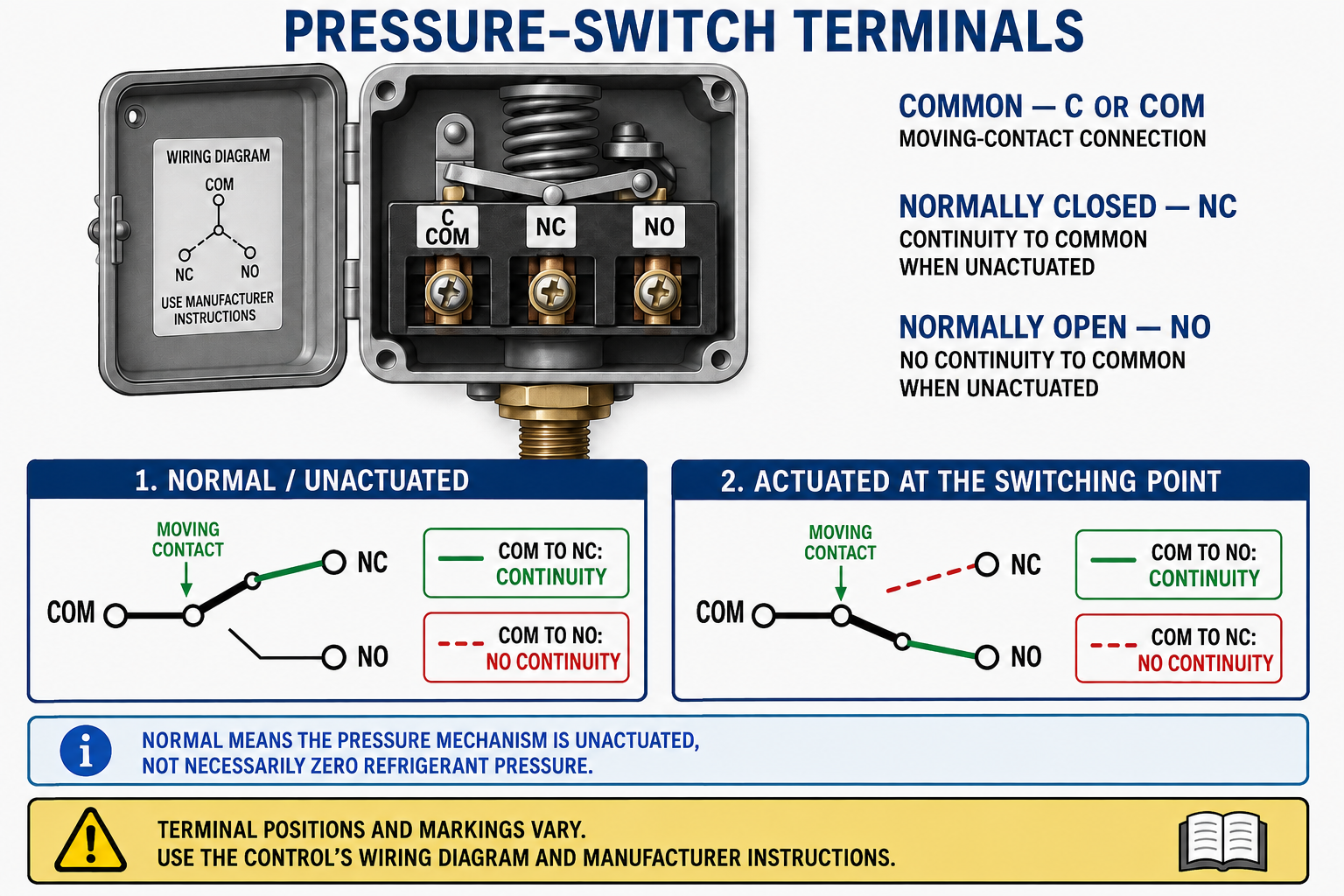
SPST
A single-pole, single-throw switch has one controlled path that opens or closes at the pressure event.
SPDT
A single-pole, double-throw switch transfers a common terminal between two contact paths.
DPST
A double-pole, single-throw switch opens or closes two electrically separate paths together.
Electronic Input
Some switches provide a dry-contact input to a controller rather than directly switching a contactor or motor load.
One manufacturer may use C, NC, and NO; another may use numbers, colors, LINE and MOTOR markings, or a switch-action diagram. A wrong terminal assumption can reverse the diagnosis or create an unsafe circuit.
Pressure Determines What the Meter Should Show
Before connecting a meter, determine whether the selected contact path should be open or closed at the present pressure. Use the control’s switch action, actual sensed pressure, cut-in, cut-out, differential, and reset condition.
Opens at the Low Event
The controlled path is expected to open when pressure falls to cut-out and close when pressure rises to cut-in on an automatic-reset model.
Opens at the High Event
The controlled path is expected to open when pressure rises to cut-out and close when pressure falls to cut-in on an automatic-reset model.
A manual-reset control can remain electrically open after pressure has recovered. Confirm whether it is locked out and whether the specified pressure condition has been met before expecting the contacts to close.
De-Energize Whenever the Test Allows
Live parts must generally be de-energized before work is performed on or near them unless an applicable exception is established. De-energization must be verified with test equipment; an open disconnect, indicator light, thermostat setting, or silent machine is not proof of zero voltage.
Identify Every Energy Source
Consider separate indoor and outdoor supplies, control transformers, disconnects, generators, stored energy, induced voltage, and possible backfeed.
Apply Required Energy Control
Follow the employer’s lockout/tagout and electrical safe-work procedures for the equipment and task.
Verify Absence of Voltage
A qualified person uses appropriate test equipment to verify that exposed circuit parts are de-energized.
Control Stored Pressure
Electrical isolation does not remove refrigerant pressure or other stored energy from the pressure switch and its sensing connection.
Test instruments, leads, probes, and accessories must be inspected, correctly rated for the circuit and environment, and used with the safe-work practices and protective equipment required for the hazard.
Test the Contact Path With Power Off
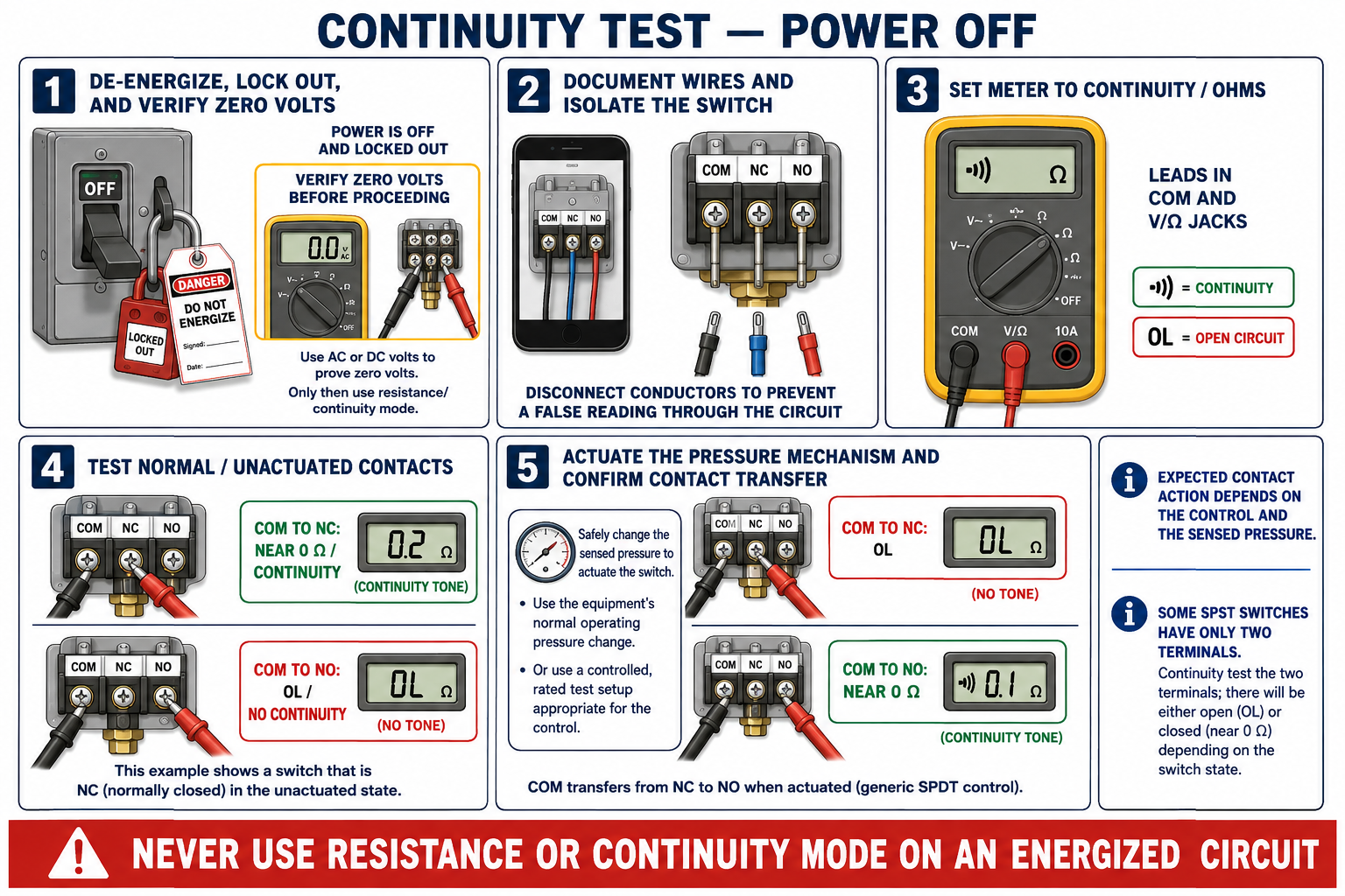
- Identify the exact contact path and its expected state at the present pressure.
- De-energize the equipment, apply required energy-control procedures, and verify absence of voltage.
- Document wire positions and isolate at least one side of the contact path when necessary to eliminate parallel circuit paths.
- Select continuity or the appropriate resistance range and verify basic meter operation according to the meter manufacturer’s procedure.
- Place one probe on each terminal of the selected contact path without allowing the probes to contact grounded metal or other terminals.
- Compare the reading with the expected contact state and the pressure acting on the control.
Why isolate the contact path: A connected relay coil, controller, indicator, winding, or alternate wiring path can make an open switch appear to have continuity. Disconnecting the appropriate conductor prevents the meter from reading through the rest of the circuit.
Interpret the Reading, Not Just the Beep
Closed Contact Path
A sound closed contact normally measures very low resistance, close to the resistance of the test leads and connections.
Open Contact Path
An open contact normally displays OL, infinity, or another meter indication of an open circuit.
Unexpected Resistance
Significant or unstable resistance across a contact expected to be closed can indicate contamination, pitting, loose terminals, damaged contacts, or poor probe connection.
Unexpected Continuity
Continuity through an expected-open path can result from welded contacts, wrong terminals, an unisolated parallel path, or incorrect pressure assumptions.
A meter may beep at a resistance higher than a sound switch contact should have. Read the displayed resistance and compare it with lead resistance, circuit requirements, and manufacturer specifications instead of relying only on the audible tone.
One Path Opens as the Other Closes
For a de-energized and isolated SPDT switch, test common to each switched terminal. At a stable pressure away from the operating point, one path should normally show continuity while the other shows open. When the pressure mechanism changes state, those readings should transfer.
C to NC Closed
C to NC shows low resistance while C to NO shows open.
C to NO Closed
C to NO shows low resistance while C to NC shows open.
The NC and NO labels refer to the manufacturer’s defined unactuated position, not necessarily normal system operation or zero pressure. Follow the switch-action diagram for the actual model.
Measure the Voltage Drop Across the Contacts
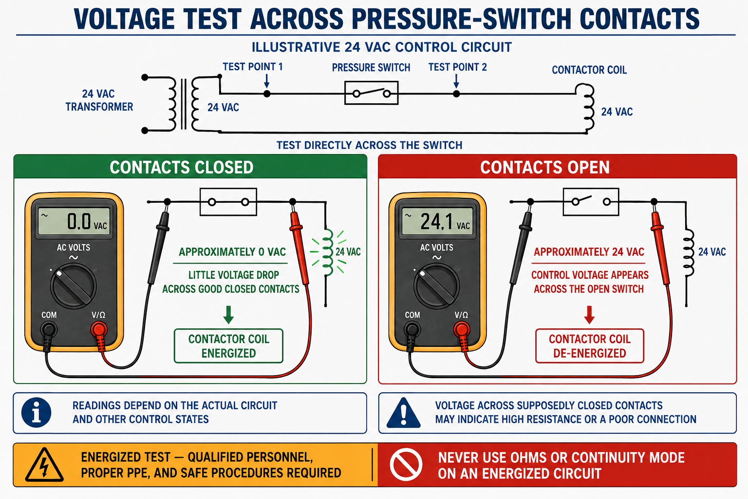
A voltage-across-the-contacts test places one probe on each side of the selected switch contact path. The meter measures the electrical potential difference across that component, not voltage from either terminal to ground.
Approximately 0 V Across
A sound closed switch behaves like a conductor and normally has little voltage drop across its contacts.
Available Circuit Voltage Across
In a complete energized series circuit with a valid return path through the load, an open switch normally has approximately the available control voltage across it.
An open downstream limit, disconnected load, open transformer secondary, controller output, broken conductor, or missing return path can prevent full control voltage from appearing across an open pressure switch. Interpret the entire circuit, not one expected number in isolation.
Use Pressure and Circuit Logic Together
Expected Closed, Near 0 V
The voltage-drop result agrees with a closed contact path, but pressure and downstream operation should still be confirmed.
Expected Open, Full Voltage
The result agrees with an open contact interrupting an otherwise complete energized circuit.
Expected Closed, Significant Voltage
The contact may be open or resistive, or the probes may be on the wrong terminals. Verify pressure, wiring, meter range, and circuit reference.
Expected Open, Near 0 V
The circuit may be de-energized, open elsewhere, backfed to the same potential on both sides, bypassed, or tested across the wrong contact path.
Excessive resistance may create a measurable voltage drop under load even though a continuity test appeared acceptable. Compare the measured drop with the circuit requirements and the control manufacturer’s specifications.
Terminal-to-Common Tests Answer a Different Question
Measuring from each switch terminal to the circuit’s correct electrical reference can help locate where voltage is present or lost. The reference may be the opposite transformer leg, neutral, or another circuit conductor identified by the wiring diagram; it is not automatically equipment ground.
Evaluates Contact Drop
Compares the two sides of the selected contact path directly.
Traces Circuit Potential
Shows whether each terminal is at the expected potential relative to the circuit reference.
Ground is not a universal control-circuit return: Using equipment ground as the reference without confirming the circuit design can produce misleading readings and can create additional exposure during testing.
Know What Can Fool the Meter
Parallel Paths
Connected loads or alternate wiring can create apparent continuity around an open contact.
Backfeed
Another transformer, control board, alarm circuit, or connected component can energize a conductor from the load side.
High-Impedance Meter Voltage
Capacitive coupling or electronic circuitry can produce a measurable voltage that cannot supply meaningful load current.
Wrong Contact Path
Testing common to the wrong SPDT terminal can make correct switch action appear reversed.
Pressure at the Wrong Location
A gauge and switch may see different pressures because of valve position, restriction, trapped pressure, or connection location.
Unstable Pressure
Pressure moving around an operating point can cause contacts and readings to change while the measurement is being made.
Pressure, Contacts, and Circuit Must Agree
- Review the sequence of operation and identify the pressure switch’s exact function.
- Read the control label and wiring diagram to identify terminals, switch action, settings, and reset method.
- Measure the pressure acting on the switch and determine the expected contact state.
- When possible, de-energize, verify absence of voltage, isolate the path, and test resistance or continuity.
- If an energized test is justified and authorized, use the required safe-work practices and measure voltage directly across the selected contacts.
- Trace terminal-to-reference voltage only with the correct circuit reference identified from the diagram.
- Observe contact operation at the specified cut-in and cut-out pressures through the required operating cycles.
- Correct the system, sensing, wiring, or switch problem and restore all wires, covers, locks, and protective devices before operation.
Bypassing a pressure switch defeats its control or safety function. Any temporary diagnostic action must be specifically permitted by applicable procedures, remain under the qualified person’s control, and be removed before the equipment is returned to service.
Avoid These Meter-Testing Errors
“Continuity can be tested on a live circuit.”
Resistance and continuity functions are used only after the circuit is de-energized, verified safe, and isolated as required.
“Zero volts across the switch proves it is good.”
Zero volts can indicate closed contacts, but it can also occur when the circuit is de-energized or both terminals are at the same potential.
“Full voltage across the switch proves it is defective.”
Full control voltage across an open switch may be exactly correct when pressure has operated the control.
“A continuity beep proves the contacts are sound.”
The beep threshold may allow more resistance than the circuit should have, and connected parallel paths can create a false indication.
Can You Interpret the Electrical Test?
- Why must pressure-switch terminals be identified from the exact control diagram?
- What information determines whether a contact path should be open or closed?
- Why must continuity testing be performed on a de-energized circuit?
- Why may one wire need to be disconnected before a continuity test?
- What resistance should a sound closed contact normally show?
- What should an open contact normally show on a resistance meter?
- What voltage is normally measured across sound closed contacts in an energized circuit?
- What voltage can appear across open contacts in a complete energized series circuit?
- Why might an open switch have little or no voltage across it?
- Why is terminal-to-ground not always the correct control-circuit test?
- How can an SPDT switch be tested for transfer action?
- Why must the electrical result always be compared with measured pressure?
What You Should Have Learned
Pressure-switch terminals and contact paths must be identified from the exact model’s diagram.
The expected contact state depends on sensed pressure, switch action, operating points, and reset condition.
Resistance and continuity tests require a de-energized, verified-safe circuit and an isolated contact path when necessary.
A sound closed contact normally has very low resistance, while an open contact shows an open circuit.
Closed contacts normally have little voltage across them under load, while open contacts can have the available control voltage across them.
Voltage-across and voltage-to-reference measurements answer different circuit questions.
Parallel paths, backfeed, electronic circuits, wrong references, and pressure differences can create misleading readings.
Electrical test results must be compared with actual pressure and verified contact operation before a switch is condemned.