Adjustable Pressure Controls with Offset Differential
Adjustable pressure controls do not all display or change their operating points in the same way. A range adjustment may establish cut-in, cut-out, or move both operating points together, while a differential adjustment determines the separation between contact events.
On an offset-differential control, the scale commonly displays one operating point and the differential. The second operating point must be calculated by adding or subtracting the differential according to whether the control opens on falling pressure or rising pressure.
What You Will Learn
By the end of this lesson you should be able to:
Identify the scale arrangement.
Determine whether a control displays cut-in, cut-out, both operating points, or one point plus differential.
Explain range adjustment.
Describe how a range adjustment establishes or moves an operating point.
Explain differential adjustment.
Describe how the differential adjustment changes the separation between contact events.
Calculate an offset operating point.
Add or subtract differential after confirming whether the control is open-low or open-high.
Set the control safely.
Remain within the permitted range, differential, pressure, and equipment limits.
Verify measured operation.
Confirm actual cut-in and cut-out pressures over repeated operating cycles.
Range and Differential Perform Different Jobs
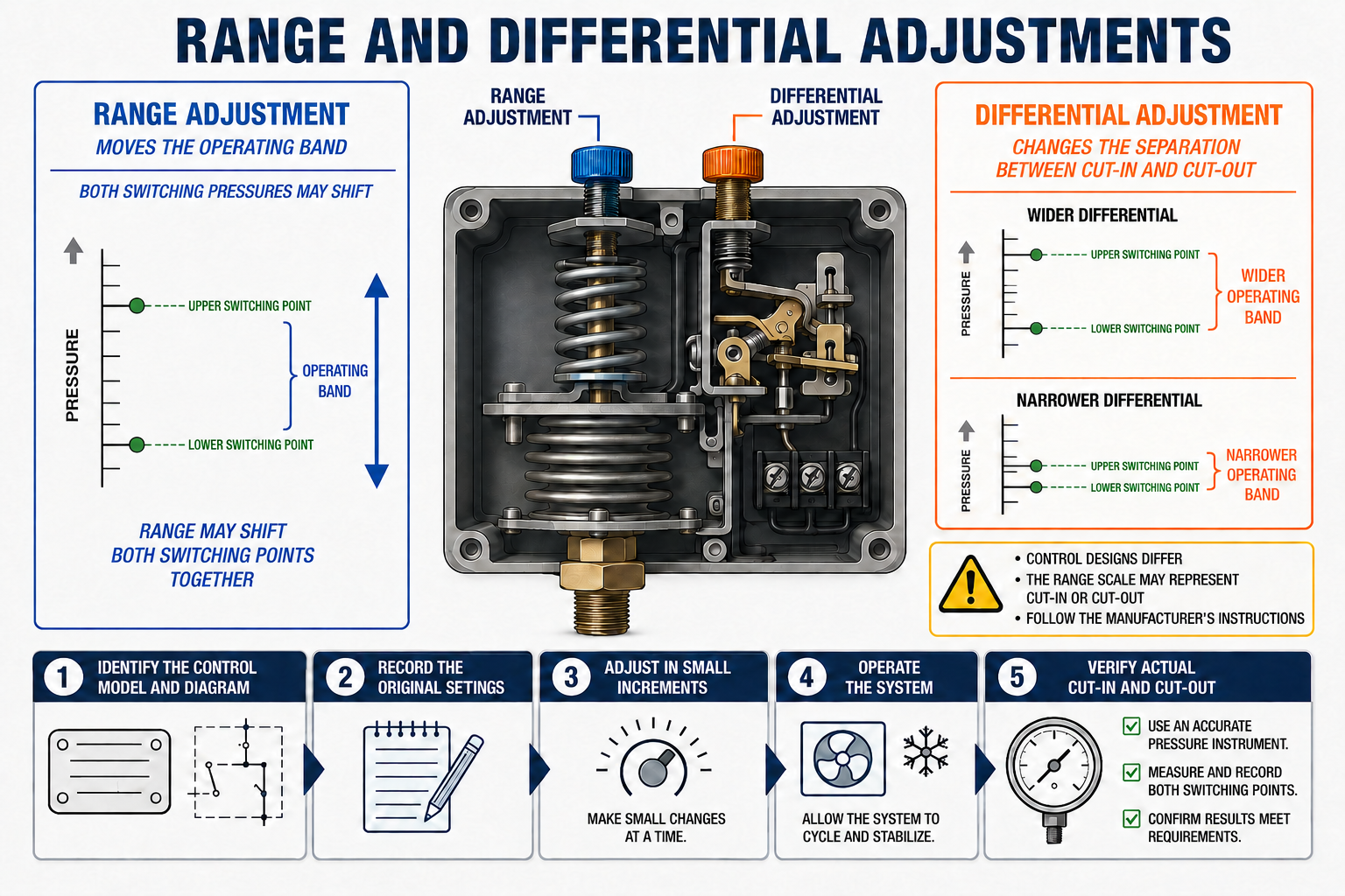
Positions an Operating Point
The range mechanism establishes the operating point shown on the control or moves the operating relationship through the permitted pressure range.
Changes the Separation
The differential mechanism changes the pressure distance between contact opening and closing within the control’s stated limits.
On one control, RANGE may indicate cut-in. On another, it may indicate cut-out. A range screw may move both operating points, and a differential screw may move either the low event or the high event. Use the exact model instructions.
Determine What the Control Displays
Cut-In and Cut-Out
Both operating points are displayed directly. The indicated differential is the difference between the two pointers or values.
Cut-In and Differential
The control displays cut-in and the pressure separation. Cut-out must be calculated for an open-low application.
Cut-Out and Differential
The control displays cut-out and the pressure separation. Cut-in must be calculated for an open-high application.
Range with Fixed Differential
One operating point is adjustable, while the other follows at a factory-established offset.
Before calculating anything, identify the value displayed by the range scale, the meaning of the differential scale, the terminal path being controlled, and whether the contact action is open-low or open-high.
One Point Is Displayed and the Other Is Calculated
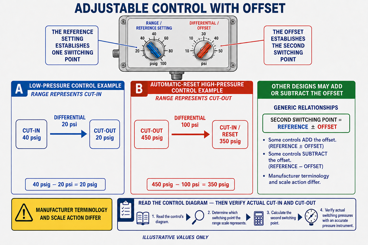
The word offset describes the second operating point being separated from the displayed range setting by the differential value. The direction of that offset depends on switch action.
Cut-Out Is Below Cut-In
Cut-out = cut-in − differential.
Cut-In Is Below Cut-Out
Cut-in = cut-out − differential.
Do not subtract automatically: First confirm which operating point the range scale displays. The subtraction formulas above apply to the stated common arrangements, not to every pressure-control mechanism.
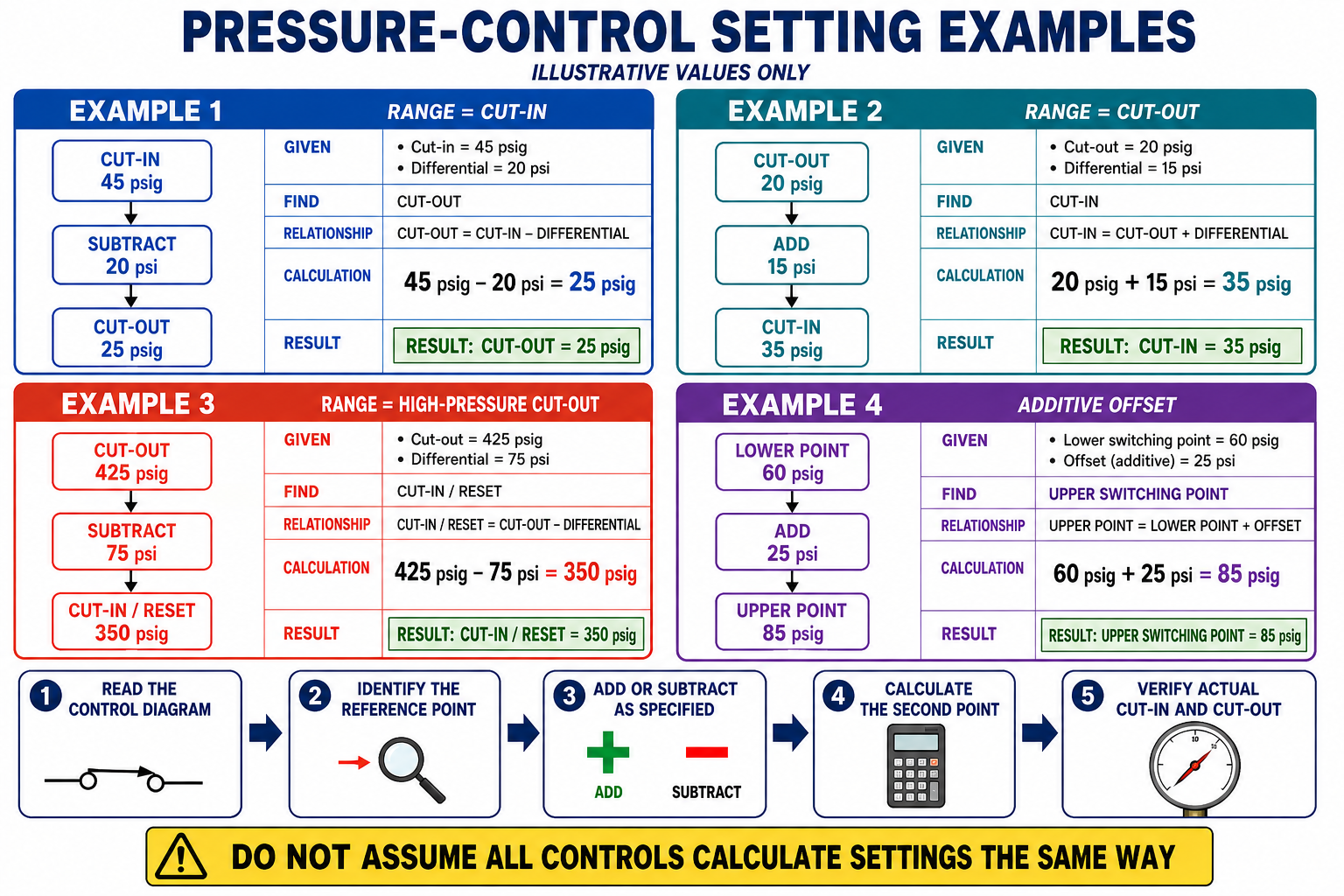
Range Displays Cut-In
Consider an automatic-reset open-low control whose manufacturer identifies the RANGE scale as cut-in and the DIFF scale as differential. The desired cut-in is 45 psig and the desired differential is 25 psi.
Pressure Rises to 45 psig
The controlled contact path closes at cut-in.
Pressure Falls to 20 psig
The controlled contact path opens at cut-out.
In this scale arrangement, leaving cut-in at 45 psig while increasing differential lowers the calculated cut-out. Decreasing differential raises cut-out closer to cut-in.
Range Displays Cut-Out
Consider an automatic-reset open-high control whose manufacturer identifies the RANGE scale as cut-out and the DIFF scale as differential. The desired cut-out is 425 psig and the desired differential is 75 psi.
Pressure Rises to 425 psig
The controlled contact path opens at cut-out.
Pressure Falls to 350 psig
The automatic-reset controlled path closes at cut-in.
A manual-reset high-pressure safety remains locked out after the pressure falls. Follow the manufacturer’s required pressure recovery and reset procedure rather than treating the reset point as an automatic cut-in.
Work From the Required Operating Points
Cut-In 50 psig, Cut-Out 15 psig
Differential = 50 − 15 = 35 psi.
If RANGE displays cut-in, set RANGE to 50 psig and DIFF to 35 psi.
Cut-Out 450 psig, Cut-In 375 psig
Differential = 450 − 375 = 75 psi.
If RANGE displays cut-out, set RANGE to 450 psig and DIFF to 75 psi.
Examples are instructional: They demonstrate calculation only. Actual settings must come from the equipment manufacturer and must fall within the exact control’s range, differential, pressure, and safety limits.
Range May Move the Entire Operating Band
Some all-range controls display cut-in and cut-out directly. On these designs, the range adjustment can move both operating points up or down together while maintaining the selected differential. A separate differential adjustment changes one event and therefore changes the separation.
20 psig to 45 psig
Cut-out is 20 psig, cut-in is 45 psig, and differential is 25 psi.
30 psig to 55 psig
Both points increased by 10 psi while the 25 psi differential remained unchanged.
The example illustrates a band movement, but it does not define how every range screw operates. On some controls the range scale establishes only one event and the differential adjustment positions the other.
Clockwise Is Not a Universal Instruction
Manufacturers may use different mechanisms even within related product families. Turning a range screw clockwise may raise a setpoint on one control and lower it on another. Turning a differential screw may increase the differential, decrease the lower event, or raise the low event depending on the design.
Identify the Model
Use the complete model number and product label, not only the enclosure appearance or brand name.
Obtain the Instructions
Use the installation or service document for that exact series, switch action, range, and reset option.
Make Small Adjustments
Move the adjustment in controlled increments and remain within all scale limits.
Measure the Result
Observe actual contact operation instead of assuming a screw turn produced a specific pressure change.
Every Combination May Not Be Available
A control can have a broad range scale but a limited differential range. The desired cut-in and cut-out may each appear to be within the overall scale while their combination places one point outside the control’s permitted operating area.
Is the Displayed Point Allowed?
Confirm that the selected range value falls between the minimum and maximum stated for the model.
Is the Separation Allowed?
Confirm that the calculated differential falls within the permitted minimum and maximum.
Operating beyond the indicator marks can damage adjustment threads or the internal mechanism and can produce inaccurate control operation. Select a different control when the required settings fall outside the approved range.
A Reliable Adjustment Method
- Identify the exact control model, switch action, terminal path, reset method, pressure range, and differential range.
- Obtain the required cut-in and cut-out values from the equipment manufacturer’s specifications.
- Determine what the range and differential scales represent on that control.
- Calculate the required differential by subtracting the lower operating pressure from the higher operating pressure.
- Calculate the offset operating point and confirm that both pressures fall within the permitted control range.
- Follow the manufacturer’s specified adjustment direction and remain within all indicator marks.
- Connect reliable pressure instruments where they represent the pressure sensed by the control.
- Operate the equipment through the required cycles and record actual cut-in and cut-out pressures.
- Readjust only as necessary, then verify the complete system sequence and reinstall any adjustment lock or cover.
A single contact event does not establish repeatable calibration. Manufacturer guidance for current electromechanical controls commonly requires operation through multiple cycles while comparing measured pressures with the specified setpoints.
Avoid Misadjusting the Control
“RANGE always means cut-in.”
Range can indicate cut-in, cut-out, or move an operating band depending on the control design.
“Differential is added in every application.”
The second point may be above or below the displayed point. Identify switch action and scale meaning before adding or subtracting.
“Clockwise always raises the setting.”
Adjustment direction varies by control and can even differ among designs from the same manufacturer.
“The scale setting proves calibration.”
The scale is a reference. Actual cut-in and cut-out pressures must be measured during operation.
Can You Set an Offset-Differential Control?
- What does a range adjustment commonly establish or move?
- What does the differential adjustment change?
- Why must the scale arrangement be identified before calculating settings?
- What is meant by an offset operating point?
- An open-low control displays cut-in at 50 psig and differential at 30 psi. What is cut-out?
- An open-high control displays cut-out at 450 psig and differential at 80 psi. What is cut-in?
- How can increasing differential affect cut-out when an open-low control’s cut-in remains fixed?
- How can a range adjustment move both operating points on some controls?
- Why is clockwise not a universal adjustment direction?
- Why can two acceptable individual scale values still create an unacceptable combination?
- Why must a manual-reset control not be treated as an automatic-reset offset calculation?
- What must be measured after the scale adjustments are made?
What You Should Have Learned
Range and differential adjustments affect different parts of the control’s operating relationship.
A scale may display both operating points, one point plus differential, or a range value with fixed differential.
On a common open-low offset control, cut-out equals displayed cut-in minus differential.
On a common open-high offset control, cut-in equals displayed cut-out minus differential.
The meaning and direction of each adjustment must come from the instructions for the exact control.
Both operating points and the differential must remain within the control and equipment limits.
Manual-reset operation must be interpreted by its specified reset procedure rather than automatic cut-in math.
Scale settings must be confirmed by measuring actual cut-in and cut-out pressures through repeated cycles.