Pressure Switches: Systematic Diagnosis and Review
Pressure-switch diagnosis brings refrigeration measurements and electrical troubleshooting together. The technician must identify the control’s purpose, determine the pressure acting on it, predict the correct contact state, test the circuit safely, and verify the complete operating sequence.
This final lesson compares the major pressure-switch types and applies one repeatable workflow to operating controls, safety controls, automatic and manual reset, fixed and adjustable settings, sensing-path problems, electrical faults, and actual system-pressure conditions.
What You Will Learn
By the end of this lesson you should be able to:
Compare pressure-switch types.
Distinguish low-pressure, high-pressure, automatic-reset, manual-reset, fixed, and adjustable controls.
Interpret operating points.
Apply cut-in, cut-out, differential, range, and offset relationships correctly.
Predict contact state.
Use pressure, switch action, terminal path, and reset method to determine the expected electrical condition.
Apply electrical tests.
Select safe continuity, resistance, voltage-drop, and circuit-tracing methods.
Separate five fault categories.
Distinguish system, sensing, adjustment, wiring, and internal switch failures.
Verify the completed repair.
Confirm repeatable operating pressures, contact action, protection, and complete system performance.
Start by Identifying What the Control Is Supposed to Do
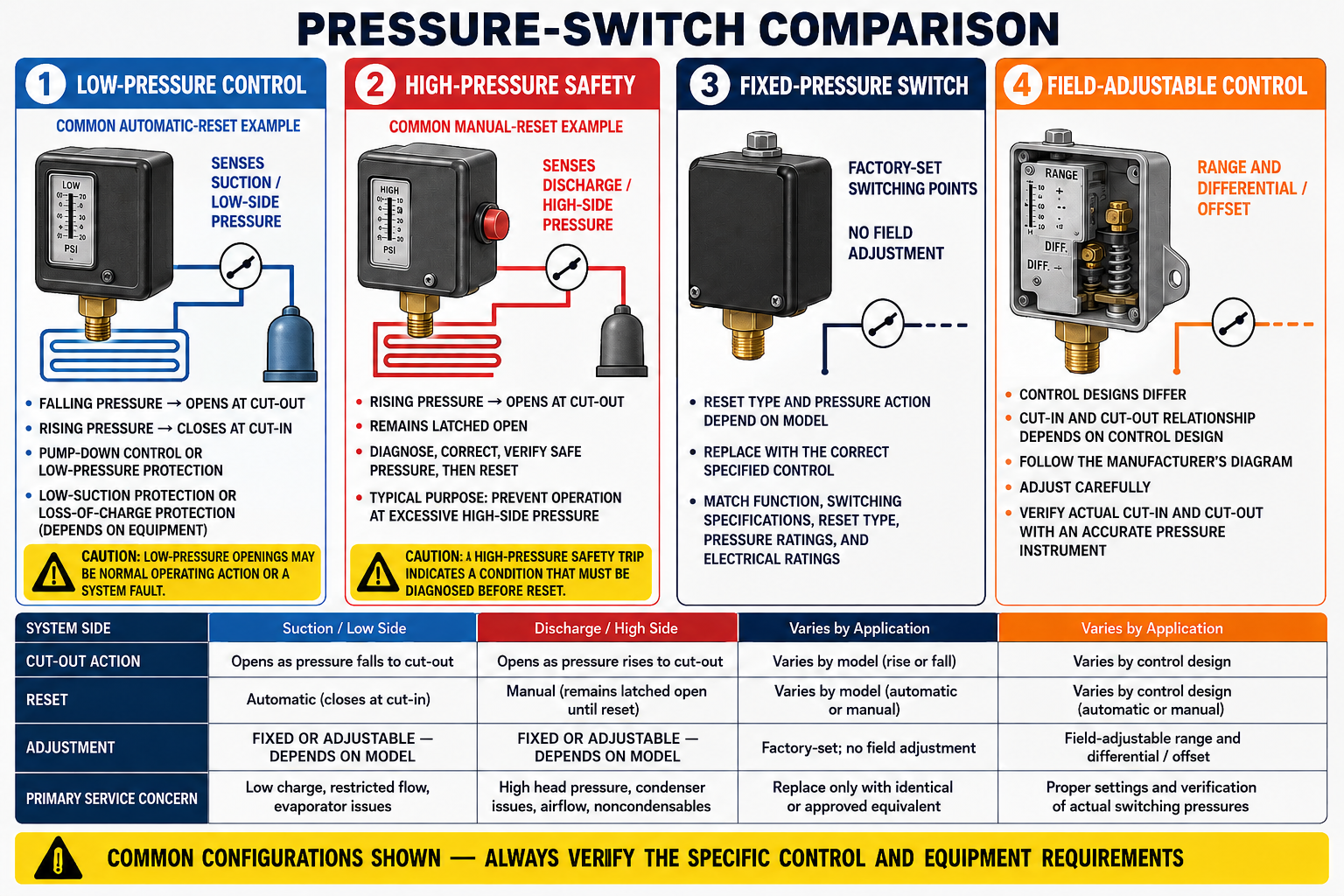
Low-Pressure Control
Monitors the low side and commonly opens a controlled path as pressure falls to cut-out.
High-Pressure Control
Monitors the high side and commonly opens a controlled path as pressure rises to cut-out.
Automatic Reset
Returns the controlled path to its operating state when pressure reaches the specified cut-in or reset point.
Manual-Reset Lockout
Remains tripped until the required pressure condition is met and the reset mechanism is deliberately operated.
Fixed Control
Uses factory-established operating values selected for a defined application.
Adjustable Control
Permits specified operating values to be set within stated range and differential limits.
A device may be a low-pressure, open-low, automatic-reset, adjustable, SPDT operating control. Another may be a high-pressure, open-high, manual-reset, fixed, SPST safety control. Record the complete description before testing or selecting a replacement.
Decide Whether the Opening Is Expected
Normal Sequence
The contacts change state as an intended part of cycling, capacity control, fan control, pump-down, or another equipment function.
Abnormal-Condition Response
The contacts open to stop or limit operation when pressure reaches a value associated with equipment damage or another hazardous condition.
A tripped control identifies where the operating sequence stopped. Preserve that evidence by recording pressure, contact state, settings, reset status, and system conditions before resetting whenever safe and practical.
Cut-In, Cut-Out, and Differential
Cut-In Is Higher
The controlled path opens on falling pressure at cut-out and closes on rising pressure at cut-in.
Differential = cut-in − cut-out.
Cut-Out Is Higher
The controlled path opens on rising pressure at cut-out and closes on falling pressure at cut-in on an automatic-reset model.
Differential = cut-out − cut-in.
Controlled Path Closes
The term describes contact action, not automatically compressor operation.
Controlled Path Opens
The term does not by itself indicate whether pressure was rising or falling.
Manual-reset exception: Pressure recovery does not automatically close a manual-reset control. Use the specified reset condition and procedure for the exact model.
Range, Differential, and Offset
Range May Display Cut-In
On a common open-low offset design, cut-out equals displayed cut-in minus differential.
Range May Display Cut-Out
On a common open-high offset design, cut-in equals displayed cut-out minus differential.
Both Points May Be Displayed
A range adjustment may move both operating points together while maintaining the selected differential.
Differential May Be Fixed
Some controls permit range adjustment but use a factory-established separation between operating events.
Use the instructions for the exact model, remain within all indicator marks and ratings, and verify actual contact operation with reliable pressure instruments through repeated cycles.
Use One Repeatable Workflow
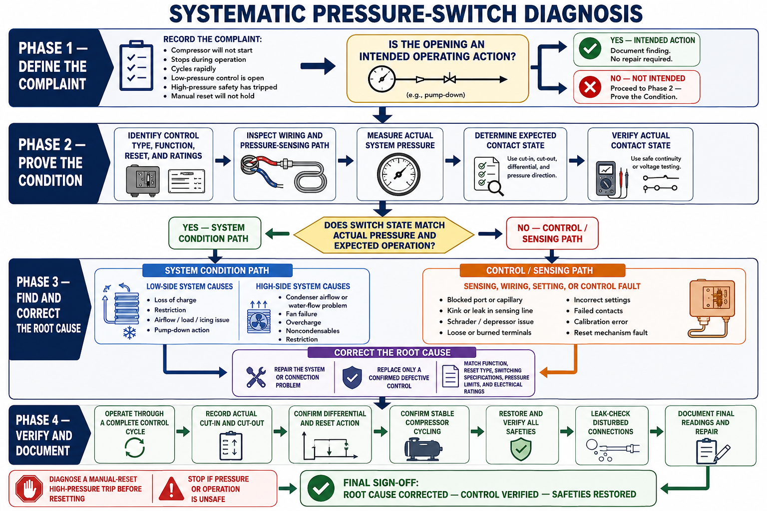
1. Identify the Complaint
Determine what stopped, when it stopped, whether the control is currently tripped, and whether anyone reset or adjusted it.
2. Identify the Application
Determine whether the switch provides operating control, pump-down, safety cutout, fan cycling, alarm input, or another function.
3. Identify the Exact Control
Record model, pressure range, contact arrangement, switch action, reset method, settings, ratings, and pressure connection.
4. Predict the Contact State
Use the sequence, terminal path, pressure direction, operating points, and reset condition.
5. Measure Pressure
Observe the system before, during, and after the contact event whenever safe and appropriate.
6. Verify the Sensing Path
Inspect fittings, capillary tubes, hoses, valves, routing, restrictions, leaks, and trapped pressure.
7. Verify Settings
Confirm cut-in, cut-out, differential, range meaning, reset condition, adjustment limits, and equipment specifications.
8. Test the Circuit
Use safe continuity, resistance, voltage-drop, and circuit-tracing methods to compare expected and actual contact state.
9. Correct the Cause
Repair the system, sensing, setting, wiring, connection, or internal switch problem proven by the evidence.
10. Verify and Document
Test repeated operation, restore all protections, and document measurements, settings, repair, and final performance.
Place the Evidence in the Correct Category
1. System-Pressure Problem
The switch sees the actual pressure, changes state at the correct value, and is responding to a refrigeration, airflow, waterflow, load, valve, or heat-rejection condition.
2. Sensing-Path Problem
The switch receives delayed, trapped, leaking, restricted, or otherwise unrepresentative pressure through its connection.
3. Setting or Selection Problem
The operating point, differential, range, reset method, switch action, rating, or replacement control does not match the application.
4. Wiring or Circuit Problem
The pressure mechanism acts correctly, but wrong terminals, loose connections, damaged conductors, backfeed, parallel paths, or another open device affects operation.
5. Internal Switch Failure
The control changes state at the wrong pressure, does not transfer, cannot reset as specified, leaks, has excessive contact resistance, or operates nonrepeatably.
More Than One Problem
A system can have combined faults, such as a dirty condenser and damaged contacts or a refrigerant leak and an incorrectly adjusted low-pressure control.
Determine whether the abnormal result is the cause, an effect, or a separate condition. Continue until the complete sequence explains the complaint and the repair is verified.
Choose the Test That Answers the Question
Continuity or Resistance
With the circuit de-energized, verified safe, and isolated as required, determines whether the selected contact path is electrically open or closed.
Voltage Across Contacts
In an energized circuit, closed contacts normally have little voltage drop, while open contacts can have the available control voltage across them when a valid return path exists.
Voltage to Circuit Reference
Traces potential through the control circuit using the correct reference identified from the wiring diagram.
Pressure and Contact Observation
Shows whether electrical state changes at the specified cut-in, cut-out, trip, and reset conditions.
A jumper only forces an electrical path closed and defeats the pressure response. It does not prove the switch is defective, does not control hazardous energy, and must never remain as a repair.
Low-Pressure Switch Opens During Cooling Demand
Observation
The thermostat continues to call, but the compressor stops and the automatic-reset low-pressure control is open.
Pressure Evidence
Suction pressure reached the specified cut-out and the contacts opened at the correct value.
Control Conclusion
The pressure switch is responding correctly and should not be replaced based on the open state.
Next Diagnosis
Evaluate refrigerant feed, system charge and leaks, evaporator airflow or load, icing, valve position, and the intended pump-down sequence.
Manual High-Pressure Control Will Not Reset
Observation
The compressor is off, pressure has begun to fall, and pressing the reset button does not restore the circuit.
Required Check
Determine whether the sensed pressure has fallen far enough to satisfy the exact model’s reset condition.
Cause Check
Inspect condenser airflow or waterflow, valves, restrictions, charge condition, noncondensables, ambient conditions, and the sensing path.
Control Conclusion
Condemn the control only if the cause is corrected, reset pressure is satisfied, the specified procedure is followed, and the mechanism still fails.
Gauge Pressure and Switch State Disagree
Observation
The gauge indicates pressure should have reset the switch, but the automatic-reset contact path remains open.
Sensing Check
Compare gauge and switch locations and inspect capillary tubing, hoses, fittings, service valves, restrictions, leaks, and trapped pressure.
Electrical Check
Verify the selected terminal path, circuit isolation, contact state, wiring, and possible parallel paths or backfeed.
Final Proof
Apply or observe known pressure at the switch connection and compare repeatable contact operation with the model specifications.
Match More Than the Setpoint
Function and Switch Action
Match operating or safety purpose, open-low or open-high action, and the required contact arrangement.
Pressure Performance
Match cut-in, cut-out, differential, operating range, maximum working pressure, and tolerances.
Reset Method
Preserve automatic reset or manual-reset lockout as specified by the equipment manufacturer.
Electrical Rating
Match voltage, phase, current, load type, pilot duty, full-load, locked-rotor, and AC or DC requirements.
Physical Requirements
Match pressure connection, capillary length, mounting, enclosure, environment, and access requirements.
Compatibility and Approval
Verify refrigerant and oil compatibility, equipment-manufacturer approval, required listings, and applicable code requirements.
A Restart Is Not the End of the Diagnosis
- Confirm the proven cause has been corrected rather than hidden by adjustment or reset.
- Restore all wires, terminals, fittings, valves, covers, adjustment locks, insulation, and protective devices.
- Remove every temporary jumper, test connection, forced command, and diagnostic override.
- Operate the equipment through the number of cycles required by the manufacturer.
- Measure actual cut-in, cut-out, trip, reset, pressure, temperature, airflow, and waterflow values as applicable.
- Confirm the compressor, contactor, solenoid, fans, alarms, controllers, and pressure switch follow the intended sequence.
- Verify that no protection has been defeated and every setting remains within the approved range.
- Document the complaint, evidence, diagnosis, repair, final settings, and verified operating results.
The final pressure readings, electrical contact state, equipment sequence, load response, and safety protection must all support the same conclusion before the equipment is returned to service.
Final Errors to Avoid
“An open switch is a bad switch.”
The switch may be correctly responding to pressure or remaining in a required manual-reset lockout.
“Pressure at the gauge is pressure at the switch.”
Connection location, restrictions, valves, trapped pressure, and sensing defects can produce different conditions.
“A jumper proves the diagnosis.”
A jumper proves only that closing that electrical path permits another part of the circuit to operate.
“If the unit restarts, the repair is complete.”
Restart does not verify correct trip pressure, reset operation, repeatability, system performance, or safety protection.
Can You Diagnose the Complete Control?
- What information is needed to completely describe a pressure switch?
- How does an operating control differ from a safety control?
- On an open-low control, which operating pressure is higher?
- On an open-high automatic-reset control, which operating pressure is higher?
- Why must manual-reset operation not be treated as automatic cut-in?
- What can RANGE and DIFF represent on different control designs?
- What five major fault categories should be considered?
- What four facts should agree when diagnosing contact state?
- What does voltage across an open switch mean in a complete energized series circuit?
- Why can a switch and gauge see different pressures?
- What evidence proves an internal pressure-switch failure?
- Why is repeated-cycle verification required after the repair?
What You Should Have Learned
Pressure switches are classified by sensing application, contact action, reset method, adjustment method, and terminal arrangement.
Cut-in closes the controlled path, cut-out opens it, and differential separates the two operating pressures.
Range and differential scales must be interpreted from the exact control’s instructions and verified by measured operation.
Actual pressure, pressure at the sensing connection, expected contact state, and measured electrical state must agree.
System, sensing, setting, wiring, and internal switch problems require different corrective actions.
Continuity, resistance, voltage-drop, and circuit-tracing tests answer different questions and must be performed safely.
A safety switch must never be permanently bypassed, and a jumper does not prove switch failure.
A completed diagnosis is verified through repeated cycles with correct pressure, contact action, equipment sequence, and protection.