Low-Pressure Switches
A low-pressure switch monitors pressure on the low side of a refrigeration system. Depending on the equipment design, it may cycle the compressor during normal operation, protect the system from an abnormal low-pressure condition, or perform both functions.
Many low-pressure controls reset automatically. When pressure falls to the cut-out point, the controlled circuit opens. When pressure later rises to the cut-in point, the circuit closes again without requiring a manual reset.
What You Will Learn
By the end of this lesson you should be able to:
Locate the low-pressure switch.
Identify where the control senses suction-side pressure and why the sensing location matters.
Explain open-low contact action.
Describe how the controlled contacts open as sensed pressure falls and close as pressure rises.
Explain automatic reset.
Describe how the switch returns to its operating state when pressure reaches the cut-in point.
Describe pump-down control.
Follow the sequence involving the thermostat, liquid-line solenoid valve, compressor, and low-pressure switch.
Recognize abnormal low-pressure conditions.
Identify system problems that can cause suction pressure to fall below the cut-out setting.
Diagnose before replacing the control.
Separate correct switch operation, sensing problems, wiring problems, and an actual control failure.
Monitoring Suction Pressure
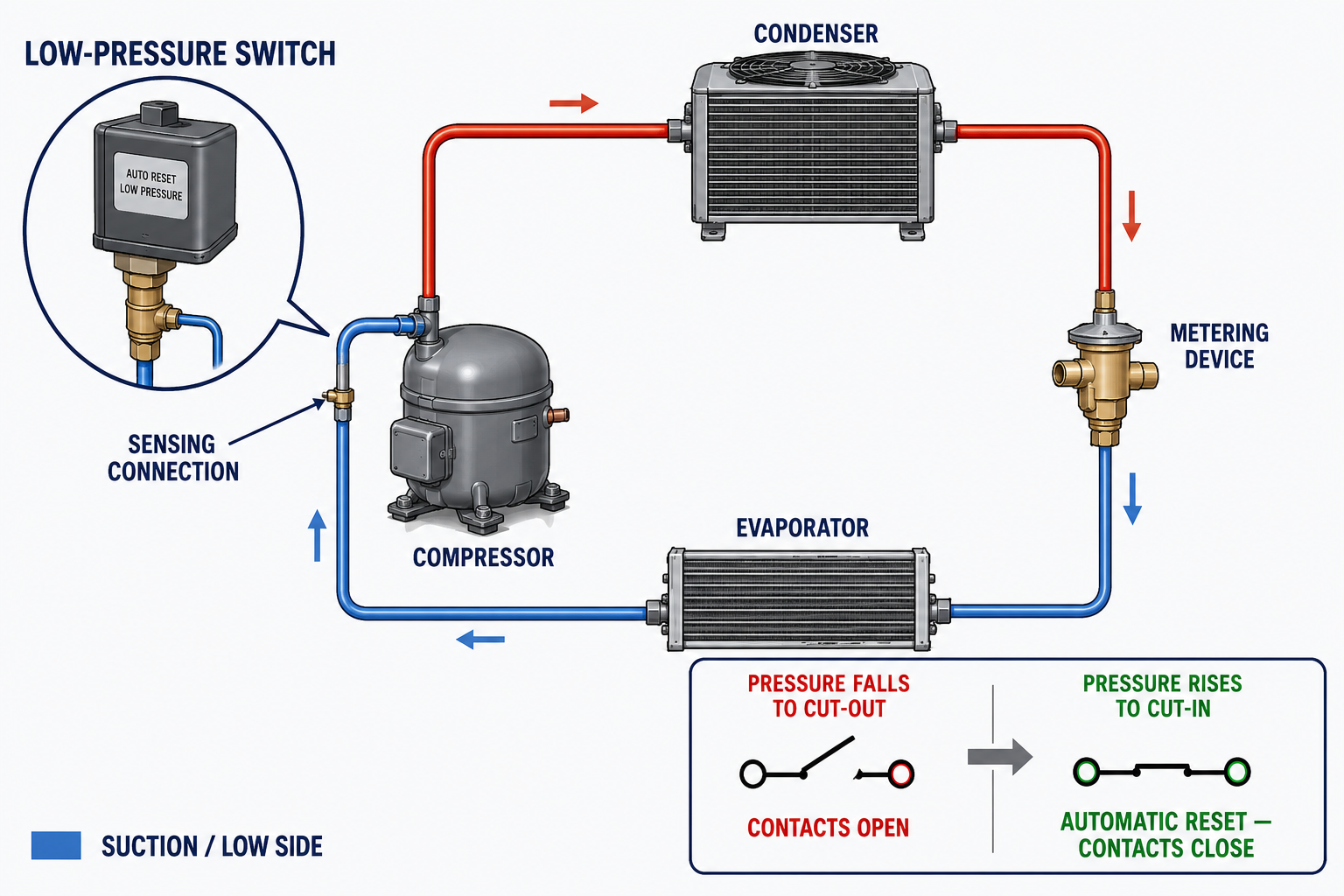
The low-pressure switch is commonly connected to the suction side of the system. System pressure acts through a fitting, tube, hose, or capillary connection on the control’s pressure-sensing element.
Because the switch responds to pressure at its own sensing connection, the condition of that connection is important. A restriction, leak, closed service valve, kinked capillary tube, trapped pressure, or improperly located test gauge can create a difference between the pressure acting on the switch and the pressure shown on a technician’s gauge.
A pressure reading must be interpreted with the refrigerant type, evaporator load, airflow or product temperature, equipment sequence, and manufacturer specifications. A single suction-pressure value does not identify the cause of a problem by itself.
Contacts Open as Pressure Falls
Cut-Out
When sensed pressure falls to the low-pressure cut-out setting, the controlled contact path opens and stops the load or interrupts the control circuit.
Cut-In
When sensed pressure rises to the cut-in setting, an automatic-reset control closes the controlled contact path and permits operation to resume.
An SPDT pressure switch may open one path and close another at the same operating point. Use the control diagram and terminal markings to determine which contacts operate the compressor circuit and which may operate an alarm or another control circuit.
The Control Resets When Pressure Recovers
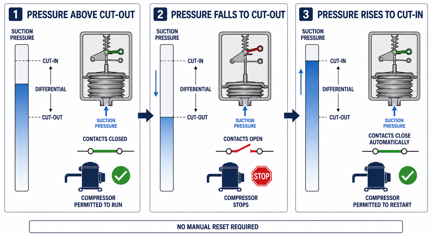
Automatic reset means that pressure movement alone can return the contacts to their operating state. No reset button must be pressed. The difference between the cut-in and cut-out pressures prevents the contacts from changing state at one identical pressure.
After cut-out, pressure must move far enough to reach the specified cut-in point. If pressure remains below cut-in, the control should remain open even though the original pressure drop has stopped.
Example only: If a control opens at 20 psig and closes at 40 psig, the controlled circuit remains open while pressure is between those values after a cut-out. Actual settings must come from the equipment and control specifications.
One Control Can Serve Different Purposes
Pump-Down Control
The low-pressure switch cycles the compressor in response to suction pressure after a liquid-line solenoid valve starts or stops refrigerant feed.
Loss-of-Charge Protection
The control may interrupt operation when a refrigerant loss causes low-side pressure to fall below the intended operating range.
Freeze Protection
On some systems, low refrigerant pressure corresponds to an evaporating temperature that could allow the evaporator or its contents to freeze.
Temperature Control by Pressure
On suitable applications, pressure may be used as an indirect indication of saturated refrigerant temperature to cycle equipment.
A setting appropriate for pump-down control may not be appropriate for freeze protection or loss-of-charge protection. Never substitute a generic pressure setting for the equipment manufacturer’s specified value.
Normal Compressor Cycling Through Suction Pressure
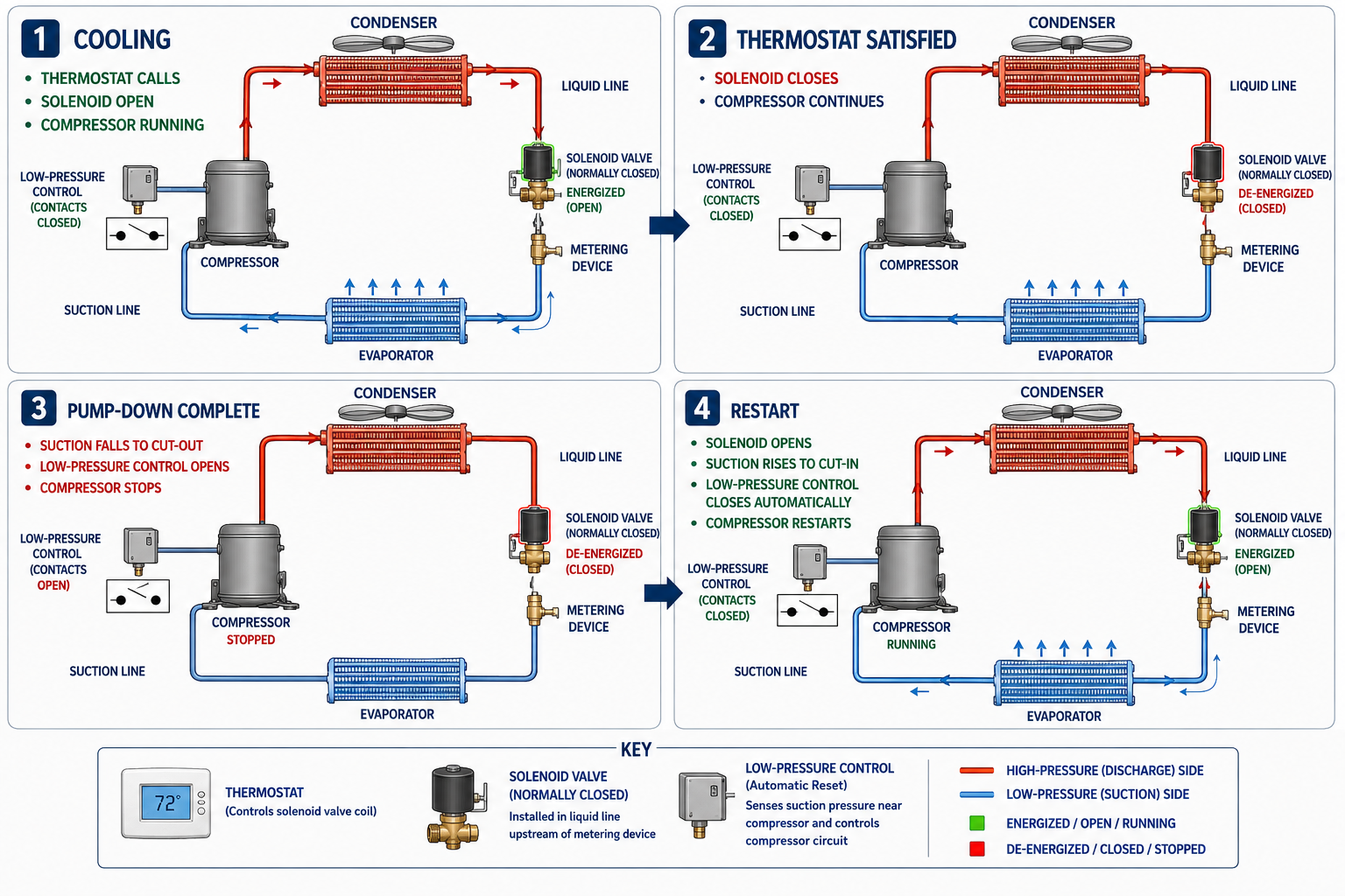
A pump-down system intentionally uses a falling suction pressure to stop the compressor after the cooling control is satisfied. The low-pressure switch opening is normal operation, not a safety trip.
1. Cooling Demand Begins
The thermostat or temperature controller energizes the liquid-line solenoid valve.
2. Refrigerant Feed Resumes
The solenoid valve opens, refrigerant enters the evaporator, and suction pressure rises.
3. Compressor Starts
At the low-pressure switch cut-in setting, the controlled contacts close and the compressor is permitted to run.
4. Cooling Demand Ends
The thermostat is satisfied and de-energizes the liquid-line solenoid valve, stopping refrigerant feed to the evaporator.
5. Compressor Pumps Down
The running compressor removes much of the remaining refrigerant vapor from the low side, causing suction pressure to fall.
6. Compressor Stops
At the cut-out setting, the low-pressure switch opens the compressor control circuit and ends the pump-down cycle.
In the basic pump-down sequence, the thermostat controls the liquid-line solenoid valve. The pressure change created by that valve’s operation causes the low-pressure switch to start and stop the compressor.
Conditions That Can Open the Switch
When a low-pressure switch opens unexpectedly, the technician must determine why suction pressure fell. The open control may be accurately reporting a system problem.
Loss of Refrigerant
A leak and resulting undercharge can starve the evaporator and reduce suction pressure.
Restricted Refrigerant Feed
A restricted metering device, filter-drier, liquid line, solenoid valve, or other component can reduce refrigerant flow to the evaporator.
Insufficient Evaporator Airflow
A failed fan, dirty filter, blocked coil, incorrect blower operation, or ice accumulation can reduce evaporator heat load and lower suction pressure.
Low Evaporator Load
Low air, water, or product temperature can reduce the amount of heat entering the evaporator and cause pressure to fall.
Incorrect Valve Position
A closed or partially closed service valve, hand valve, or liquid-line solenoid valve can produce an unintended pressure drop or stop refrigerant feed.
Incorrect Setting or Control Selection
A cut-out setting that is too high, an unsuitable differential, or the wrong pressure range can stop equipment during otherwise acceptable operation.
Automatic Reset Can Reveal an Unresolved Problem
If pressure repeatedly falls to cut-out and then rises to cut-in, an automatic-reset switch may repeatedly stop and restart the compressor. The pressure switch may be operating correctly while the equipment short cycles because the underlying condition remains.
Expected Sequence
The liquid-line solenoid closes when demand ends, suction pressure falls, and the compressor stops at cut-out. It restarts when a new demand opens the solenoid and pressure rises to cut-in.
Unexpected Sequence
The compressor cuts out during a continuing demand, pressure equalizes or recovers, and the automatic-reset control restarts the compressor without the fault being corrected.
Observe the pressure at cut-out and cut-in and compare those values with the specifications. If the contacts change state at the correct pressures, investigate the refrigeration system, evaporator load, airflow, valves, and sensing connection.
Determine Whether the Switch Should Be Open
1. Identify the Application
Determine whether the switch is an operating control, a protective control, or part of a pump-down sequence.
2. Read the Diagram and Label
Confirm the terminal path, reset method, cut-in, cut-out, differential, pressure range, and electrical rating.
3. Measure Sensed Pressure
Connect appropriate gauges and determine whether the pressure at the control should place the contacts open or closed.
4. Observe Contact Action
Verify that the controlled contact path changes state at the specified cut-out and cut-in pressures.
5. Inspect the Sensing Path
Check the pressure connection, capillary tube, hose, fittings, and service valves for damage, leakage, restrictions, or trapped pressure.
6. Diagnose the System Condition
If the switch operates at the correct pressures, find the refrigeration, airflow, load, valve, or control-sequence problem that caused the pressure change.
De-energize and verify the circuit is de-energized before resistance or continuity testing. Live-voltage diagnosis and refrigerant-system testing should be performed only by persons trained and authorized for the equipment, refrigerant, and hazards involved.
Avoid These Low-Pressure Control Errors
“Every low-pressure opening is a safety trip.”
In a pump-down system, the control intentionally opens at the end of each operating cycle.
“Automatic reset means the problem is corrected.”
Automatic reset only means pressure reached the cut-in point. It does not prove that the cause of the earlier cut-out was corrected.
“A low-pressure switch always controls the compressor directly.”
The switch often controls a contactor coil, relay, controller input, or another part of the control circuit rather than carrying compressor motor current.
“Low suction pressure always means low charge.”
Low charge is one possibility, but restricted refrigerant feed, low evaporator load, insufficient airflow, icing, valve position, and other conditions can also lower suction pressure.
Can You Explain Low-Pressure Switch Operation?
- Where is a low-pressure switch commonly connected?
- What happens to an open-low control circuit when pressure falls to cut-out?
- What happens when pressure rises to cut-in on an automatic-reset control?
- Why does a pressure switch have a difference between cut-in and cut-out?
- What does the thermostat control in a basic pump-down system?
- What starts the compressor after the liquid-line solenoid valve opens?
- Why does suction pressure fall after the liquid-line solenoid valve closes?
- Why is low-pressure cut-out normal at the end of a pump-down cycle?
- Name four abnormal conditions that can produce low suction pressure.
- Why can an automatic-reset control cause repeated compressor cycling when a fault remains?
- Why must the sensing line and valve positions be inspected during diagnosis?
- What must be verified before condemning a low-pressure switch?
What You Should Have Learned
A low-pressure switch senses pressure on the low side or suction side of the refrigeration system.
An open-low control opens its controlled contact path at cut-out as pressure falls.
An automatic-reset control closes the circuit when pressure rises to its cut-in point.
A low-pressure switch can provide operating control, protective control, pump-down control, or a combination of functions.
In a pump-down system, the thermostat controls the liquid-line solenoid valve and the low-pressure switch controls compressor cycling.
Low suction pressure can result from low charge, restricted refrigerant feed, low evaporator load, insufficient airflow, icing, or incorrect valve position.
Automatic reset can allow repeated cycling when the condition that caused low pressure remains unresolved.
A pressure switch should be replaced only after its application, sensed pressure, contact action, settings, wiring, and sensing path have been checked.