Introduction to HVAC/R Pressure Switches
Pressure switches monitor refrigerant pressure and use that pressure to operate electrical contacts. Depending on the application, those contacts may cycle equipment during normal operation or stop equipment when pressure reaches an unsafe or undesirable condition.
A technician must understand both sides of the device: the pressure-sensing side connected to the refrigeration system and the electrical-contact side connected to the control circuit.
What You Will Learn
By the end of this lesson you should be able to:
Explain the purpose of a pressure switch.
Describe how refrigerant pressure can be used to control an electrical circuit.
Identify the two sides of the control.
Distinguish the pressure-sensing connection from the electrical contacts and terminals.
Separate operating and safety functions.
Recognize that a pressure switch may cycle equipment normally or protect it from an abnormal condition.
Interpret normally open and normally closed.
Explain what the word normal means when describing electrical contacts.
Define cut-in and cut-out.
Relate cut-in to contact closing and cut-out to contact opening.
Recognize common pressure-switch categories.
Identify low-pressure, high-pressure, automatic-reset, manual-reset, fixed, and adjustable controls.
What a Pressure Switch Does
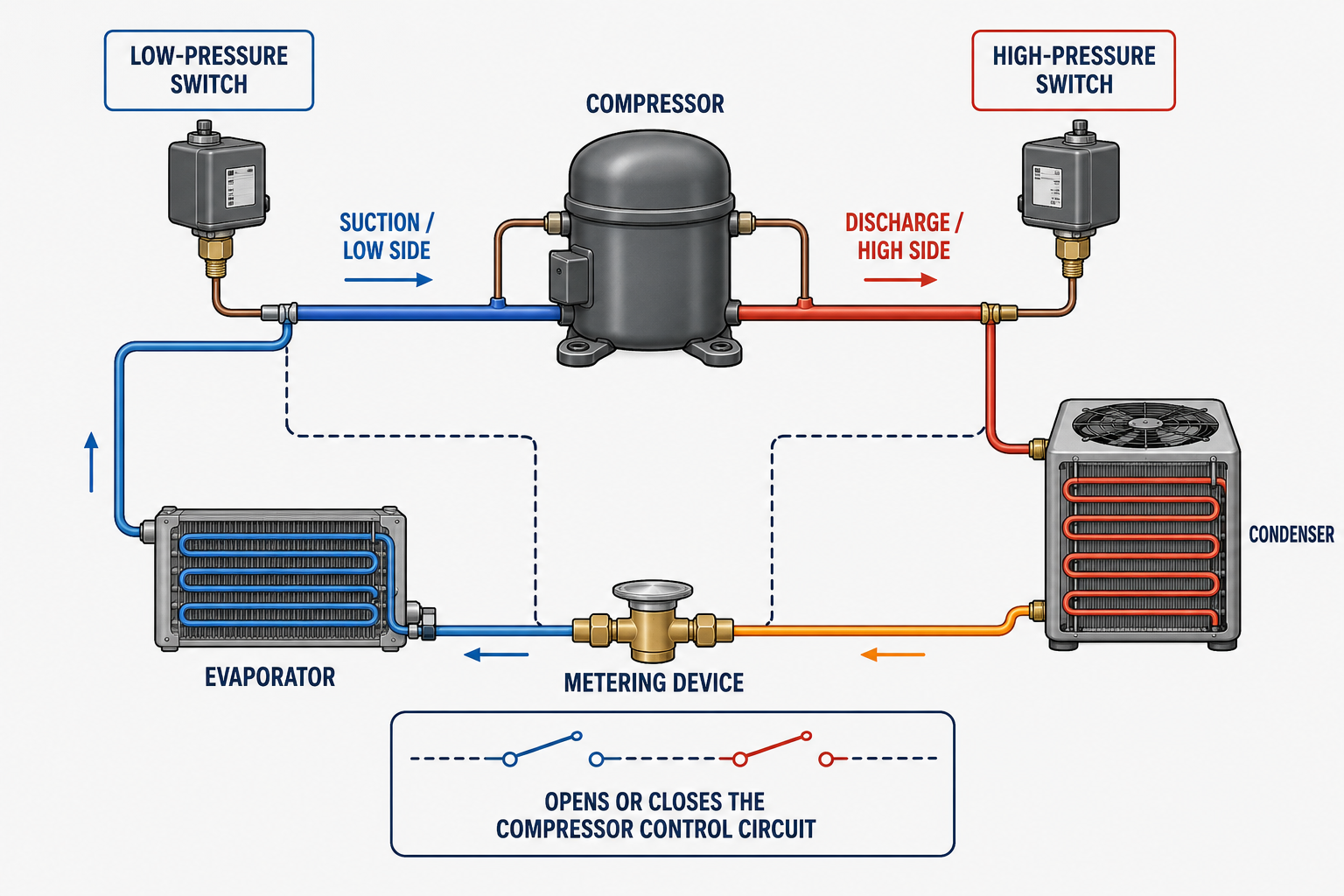
Refrigerant pressure acts on a sensing element inside the control. Depending on the design, that element may be a bellows, diaphragm, or another pressure-responsive mechanism. Movement of the sensing element operates a set of electrical contacts.
The pressure connection belongs to the sealed refrigeration system, while the electrical terminals belong to the equipment control circuit. A correct diagnosis requires pressure measurements, circuit information, and an understanding of how the switch is intended to operate.
The Switch Senses Pressure at a Selected Location
A pressure switch is connected to the refrigeration system at the location whose pressure must be monitored. A low-pressure control is commonly connected to the low side or suction side. A high-pressure control is commonly connected to the high side or discharge side.
The sensing line or fitting allows system pressure to act on the control. Refrigerant does not normally circulate through the switch as it circulates through the major system components.
The pressure at the switch connection must represent the condition the control is intended to monitor. A restricted capillary tube, closed service valve, damaged hose, leaking connection, or trapped pressure can cause the switch to respond to a pressure that does not match the technician’s gauge reading at another location.
Pressure Location Helps Define the Application
Monitors the Low Side
May provide operating control, loss-of-charge protection, freeze protection, pump-down control, or another function specified by the equipment design.
Monitors the High Side
Typically opens the control circuit when discharge or condensing pressure rises to the control’s cut-out setting.
Do not diagnose by name alone: The same general type of pressure control can be applied differently by different manufacturers. Always use the equipment wiring diagram, sequence of operation, refrigerant data, and control specifications.
Operating Control or Safety Control
Normal Cycling Function
An operating pressure control opens and closes as part of the intended operating sequence. A pump-down low-pressure control is a common example.
Abnormal-Condition Response
A safety pressure control stops equipment when pressure reaches a limit that indicates an unsafe or damaging operating condition.
A pressure switch may be doing exactly what it was designed to do. Before replacing it, determine whether the refrigeration system actually reached the pressure that should operate the control.
Pressure Changes the Contact State
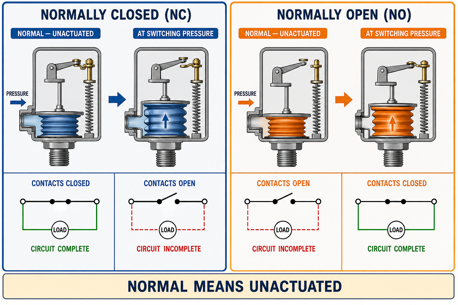
Pressure-switch contacts are described in their normal, unactuated condition. A normally closed contact provides continuity in that reference condition. A normally open contact does not provide continuity in that reference condition.
The manufacturer’s diagram defines the reference condition for the contacts. Depending on the control, that condition may be below the operating point, above the operating point, at atmospheric pressure, or with the sensing element otherwise unactuated.
SPST and SPDT Controls
SPST
A single-pole, single-throw pressure switch either opens or closes one circuit path.
SPDT
A single-pole, double-throw pressure switch transfers a common terminal between normally closed and normally open terminals.
Common Terminal
On an SPDT control, the common terminal may be marked C or COM and connects to either NC or NO according to switch position.
Manufacturer Diagram
Terminal numbers, letter markings, physical positions, and contact action vary. Identify them from the diagram supplied with the exact control.
Describe What the Electrical Contacts Do
The Controlled Circuit Closes
Cut-in is the pressure at which the control contacts close the circuit being described.
The Controlled Circuit Opens
Cut-out is the pressure at which the control contacts open the circuit being described.
Pressure may rise toward cut-out in one application and fall toward cut-out in another. For that reason, do not assume pressure direction from the terms cut-in and cut-out alone. Follow the control’s specified operating sequence.
Coming later: Lesson 5 explains cut-in, cut-out, differential, and how to calculate one setting when the other values are known.
Automatic Reset and Manual Reset
Resets With Pressure
The contacts return to their reset state automatically after pressure moves to the specified reset point.
Requires Deliberate Reset
After the pressure condition is corrected and the control permits resetting, a person must operate the reset mechanism before the circuit can return to service.
A manual-reset control is intended to call attention to a significant condition. Repeatedly resetting the control without diagnosing the system can expose equipment and personnel to additional risk.
Fixed and Adjustable Controls
Factory-Established Values
Fixed controls have operating values established by their design and are selected to match the required application.
Field-Set Operating Values
Adjustable controls allow one or more operating values to be set within the manufacturer’s stated range.
Some adjustable controls have an independently adjustable differential. Others use a fixed differential or an offset relationship in which changing one setting changes another operating value. The control’s scale, instructions, and measured operation must be considered together.
Test the System and the Circuit Safely
Verify Actual Pressure
Use appropriate, correctly connected test instruments and compare system pressure with the control’s specified operating values.
Use the Wiring Diagram
Identify the intended circuit, terminal markings, contact state, and sequence before disconnecting wires or interpreting readings.
De-energize for Resistance Tests
Turn off power, verify the circuit is de-energized, and isolate the component as required before measuring resistance or continuity.
Correct the Underlying Condition
If pressure is actually abnormal, diagnose the refrigeration or airflow problem instead of treating the pressure switch as the failure.
A jumper defeats the protective function of the control. Any temporary diagnostic procedure must follow the equipment manufacturer’s instructions, applicable safety procedures, and the limits of the technician’s training and authorization.
Avoid These Pressure-Switch Mistakes
“An open pressure switch must be defective.”
The switch may have opened correctly because system pressure reached its operating point.
“Normally closed means closed whenever the system is normal.”
Normally closed describes the contact state in the manufacturer’s defined unactuated reference condition.
“Cut-out always happens when pressure rises.”
A high-pressure control may cut out on rising pressure, while a low-pressure control may cut out on falling pressure.
“If the reset works, the system is repaired.”
Resetting restores the circuit; it does not identify or correct the condition that operated the control.
Can You Explain the Complete Control?
- What two types of systems meet at an HVAC/R pressure switch?
- How does refrigerant pressure cause an electrical action inside the control?
- Where is a low-pressure switch commonly connected?
- Where is a high-pressure switch commonly connected?
- What is the difference between an operating control and a safety control?
- What does normally closed mean?
- Why does normal not necessarily mean zero pressure?
- What is the difference between SPST and SPDT contact arrangements?
- What does cut-in describe?
- What does cut-out describe?
- How does an automatic-reset control differ from a manual-reset control?
- Why should a technician verify system pressure before condemning a pressure switch?
What You Should Have Learned
A pressure switch converts refrigerant pressure into an electrical contact action.
The sensing connection and the electrical circuit must both be considered during diagnosis.
Low-pressure controls monitor the low side, while high-pressure controls monitor the high side.
A pressure switch may serve as a normal operating control or as a safety control.
Normally open and normally closed describe contacts in their defined unactuated reference condition.
Cut-in describes circuit closing, while cut-out describes circuit opening.
Pressure switches may use automatic or manual reset and may have fixed or adjustable settings.
An open pressure switch may be responding correctly to an abnormal system condition and should not be replaced without testing.