Back to: NASCLA Master Electrical Contractor Exam Preparation
“`html
NASCLA Electrical Contractor Exam Preparation • Part VI • Lesson 55
Switches are among the most familiar electrical devices, but contractor-level examination questions go well beyond simply identifying a single-pole wall switch. You must understand how switches are connected, what conductors may be switched, how switches are rated, where they may be installed, and how common switching arrangements operate.
This lesson introduces the NEC requirements for switches and switching devices, with particular attention to the concepts most likely to appear in an open-book contractor examination.
Lesson Overview
For the NASCLA examination, switches should be viewed as electrical equipment governed by specific installation and rating requirements rather than simply as devices used to turn loads on and off. NEC Article 404 is the primary location for general switch requirements.
By the end of this lesson, you should be able to distinguish common switching arrangements, identify the conductors that may be switched, recognize important switch ratings, locate major Article 404 requirements quickly, and avoid common examination traps involving grounded conductors, grounding, accessibility, and switch selection.
NEC Article 404 — Switches
Article 404 contains requirements for switches and switching devices. On an examination, the first skill is recognizing that a question about the installation, connection, rating, grounding, or accessibility of a switch will normally send you to Article 404.
Exam Navigation Rule
If the question is primarily about a switch, begin with Article 404. If the switch controls specialized equipment such as a motor, air-conditioning unit, sign, or other specific load, another NEC article may contain additional requirements.
Installation
Article 404 addresses how switches are connected, installed, grounded, enclosed, and made accessible.
Ratings
A switch must be suitable for the voltage, current, and type of load it controls. Do not assume that every switch with the same ampere rating is suitable for every load.
Special Applications
Motors, lighting, appliances, signs, and other equipment may introduce additional requirements outside Article 404.
The Basic Switching Principle
A conventional switch controls a load by opening or closing the electrical path through a circuit conductor. When the switch is open, current through the controlled path stops. When the switch is closed, current can flow to the load.
The important examination concept is which conductor is being switched. In ordinary branch-circuit switching, the switch is placed in the ungrounded conductor so that opening the switch removes the ungrounded supply from the controlled load.
Ungrounded Conductor
Commonly called the hot conductor. This is normally the conductor interrupted by a switch.
Grounded Conductor
Commonly the neutral conductor. The NEC generally does not permit a switch or circuit breaker to disconnect only the grounded conductor.
Equipment Grounding Conductor
The equipment grounding conductor provides a fault-current path and is not used as the normal current-carrying switching conductor.
Single-Pole, Three-Way, and Four-Way Switching
Contractors are expected to recognize the purpose and basic arrangement of common switching devices. The names describe the internal switching function, not necessarily the number of physical locations from which a load can be controlled.
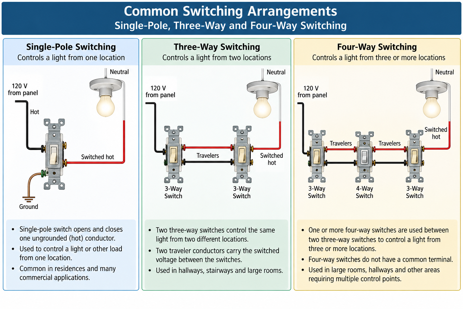
Single-Pole Switch
A single-pole switch provides basic ON/OFF control of a load from one location. It opens or closes one circuit path.
Three-Way Switches
A pair of three-way switches allows a load to be controlled from two locations. Each three-way switch has a common terminal and two traveler terminals.
Four-Way Switch
A four-way switch is installed between two three-way switches when control is required from three or more locations. Additional four-way switches can be inserted between the two three-way switches for additional control locations.
Understanding Three-Way Switching
A three-way switch is not simply an ON/OFF switch with an extra terminal. Internally, the common terminal is connected to one of two traveler terminals depending on the position of the switch.
The terminal that alternately connects to either traveler terminal.
One of the two alternate paths between the three-way switches.
The second alternate path between the three-way switches.
Because either switch can change the available current path, operating either three-way switch changes the state of the controlled load.
Do Not Memorize Switch Position
There is no universal physical “up means ON” position in a normal three-way switching arrangement. The state of the load depends on the combined positions of both switches.
Understanding Four-Way Switching
A four-way switch is used between two three-way switches. It does not replace the three-way switches at the ends of the switching arrangement.
The four-way device changes the relationship between the two traveler conductors. Depending on its position, it routes the traveler paths through the switching arrangement in one of two configurations.
Three-Way and Four-Way Switch Connections
The NEC specifically addresses the connection of three-way and four-way switches. The switching arrangement must be wired so that switching occurs in the ungrounded circuit conductor.
This requirement reinforces a broader electrical safety principle: opening a wall switch should not leave the controlled equipment connected to the ungrounded supply merely because the grounded conductor was interrupted instead.
Common Exam Trap
A diagram may appear to operate correctly while placing the switching function in the grounded conductor. Functional operation alone does not make the installation Code compliant.
Switch Ratings Matter
Switches are not selected solely by physical appearance. The device must have ratings appropriate for its application. A contractor must consider the circuit voltage, current, load characteristics, and any special equipment requirements.
Voltage
The switch must have an appropriate voltage rating for the circuit on which it is installed.
Current
The switch must have sufficient ampere capacity for the load and application.
Load Type
Lighting, motor, inductive, tungsten, electronic, and other loads can impose different switching conditions. Use a device identified and rated for its intended application.
For examination questions, carefully identify the type of load before selecting a switch. A device that appears to have an adequate general ampere rating may still be unsuitable for a particular application.
Switches Controlling Motors
Motor loads deserve special attention because starting current and motor-circuit requirements differ from ordinary resistive loads. A switch used as a motor controller or disconnecting means must satisfy the applicable motor requirements in Article 430 in addition to any applicable general switch requirements.
Accessibility of Switches
Switches and circuit breakers used as switches generally must be located so they can be operated from a readily accessible place. Article 404 also establishes requirements for the height of operating handles and provides specific exceptions for certain installations.
For a typical installation, pay attention to the maximum permitted height of the center of the grip of the operating handle when the handle is in its highest position. The NEC generally establishes this maximum at 2.0 m (6 ft 7 in.) above the floor or working platform.
Exam Number to Remember
6 ft 7 in. (2.0 m) is an important switch-operating-handle dimension. When a question asks about switch accessibility or maximum operating-handle height, Article 404 is the place to verify the requirement and any applicable exception.
Grounding Switches
General-use snap switches, dimmers, and control switches are subject to equipment-grounding requirements. In a normal new installation, the switching device must be connected to the equipment grounding system by an approved method.
A switch installed with metal screws to a properly grounded metal box can satisfy the grounding connection under applicable conditions. Another common method is connecting the equipment grounding conductor or bonding jumper directly to the switch grounding terminal.
Metal Box
The box and device must be properly bonded where the metal box is relied upon as part of the grounding connection.
Grounding Terminal
An equipment grounding conductor or bonding jumper may connect to the grounding termination provided on the switch.
Metal Faceplate
Metal faceplates must be bonded as required. Do not assume that installing a metal cover automatically establishes an acceptable grounding path.
Neutral Conductors at Switch Locations
Modern electronic switching devices may require a grounded conductor at the switch location to power electronics even when the controlled lighting load is off. Article 404 contains requirements addressing grounded conductors at certain switch locations.
This subject can become highly dependent on the exact wiring method, occupancy, switching arrangement, and Code edition. On an open-book examination, do not rely on a simplified statement such as “every switch box requires a neutral.” Read the applicable Article 404 provision and its exceptions.
Contractor-Level Exam Strategy
When the question asks whether a grounded conductor must be provided at a switch location, identify the wiring method and installation conditions first. Then read the complete Code rule, including exceptions.
Switch Enclosures and Faceplates
Switches are installed in boxes or other suitable enclosures and must be provided with appropriate covers or faceplates. Faceplates for switches mounted in boxes or enclosures must cover the opening as required, and flush-mounted devices must properly interface with the finished surface.
The enclosure, cover, device, grounding arrangement, and environmental rating all matter. A switch installed outdoors or in another demanding environment may require equipment specifically suitable for that location.
Switches in Wet and Damp Locations
When a switch is installed in a wet or damp location, the enclosure and cover arrangement must be suitable for the environment. Examination questions may test whether ordinary indoor equipment can simply be installed outdoors. It cannot unless the equipment and installation method are suitable for the location.
Switches Used as Disconnecting Means
A switch may perform more than ordinary load control. Depending on its rating, listing, and application, a switch may also serve as a disconnecting means.
Do not assume that every wall switch qualifies as the required disconnect for equipment. The applicable equipment article may specify the type, rating, location, visibility, lockability, or other characteristics of the required disconnecting means.
Control Function
Turns equipment or a load on and off during normal operation.
Disconnect Function
Provides the isolation required by the applicable NEC rule for servicing or equipment safety.
Not Automatically Equivalent
A device that performs a control function does not automatically satisfy every disconnecting-means requirement.
Common Examination Errors
Switching the Neutral
Choosing an answer that places ordinary switching only in the grounded conductor.
Confusing Three-Way and Four-Way
Using a four-way switch by itself or forgetting that four-way switches are placed between three-way switches.
Ignoring Load Type
Selecting a switch solely by ampere rating without considering whether it is suitable for the load being controlled.
Ignoring Grounding
Assuming a switch does not require grounding because it is not normally a current-carrying load.
Confusing Control and Disconnecting
Assuming an ordinary control switch automatically satisfies a specialized equipment disconnect requirement.
Stopping at Article 404
Failing to check the article governing the controlled equipment when the question involves motors, HVAC equipment, appliances, signs, or another specialized load.
NEC Reference Strategy
Efficient navigation matters on an open-book contractor examination. Rather than trying to memorize every switch requirement, learn the structure of Article 404 and recognize when another article must also be consulted.
Is the question actually about a switch, switching device, circuit breaker used as a switch, controller, or disconnect?
Determine whether the switch controls ordinary lighting or a specialized load such as a motor, appliance, HVAC unit, or sign.
Find the general switch installation, connection, accessibility, grounding, and rating requirements.
If the load is specialized, verify whether another NEC article modifies or adds requirements.
Do not stop at the first sentence that appears to answer the question. Exceptions frequently determine the correct examination answer.
Important Code Locations
Article 404 — Switches.
404.4 — Switch connections, including three-way and four-way arrangements and requirements involving grounded conductors.
404.8 — Accessibility and grouping requirements.
404.9 — General-use snap switches, dimmers, control switches, faceplates, and grounding provisions.
Article 410 — Luminaires, lampholders, and lamps; useful when the switching question is part of a lighting installation.
Article 422 — Appliances; check when a switch is associated with appliance control or disconnecting.
Article 430 — Motors, motor circuits, and controllers; essential when a switch controls or disconnects a motor.
Lesson Review
- Article 404 is the primary NEC article covering switches and switching devices.
- Ordinary switching is performed in the ungrounded circuit conductor rather than by simply interrupting the grounded conductor.
- A single-pole switch normally controls a load from one location.
- Two three-way switches provide control from two locations.
- A four-way switch is installed between two three-way switches to provide additional control locations.
- Three-way switches have a common terminal and two traveler terminals.
- Four-way switches manipulate the traveler paths between the three-way switches.
- The physical position of a three-way switch does not by itself determine whether the load is energized.
- Switch ratings must be appropriate for the circuit voltage, current, and type of load.
- Motor switching can require additional investigation in Article 430.
- Switches and circuit breakers used as switches generally must be readily accessible.
- The typical maximum height for the center of the operating-handle grip in its highest position is 6 ft 7 in. above the floor or working platform, subject to applicable exceptions.
- General-use snap switches, dimmers, and control switches are subject to equipment-grounding requirements.
- Metal faceplates must be bonded as required.
- Grounded-conductor requirements at switch locations must be evaluated using the complete applicable rule and exceptions rather than a blanket assumption that every switch box requires a neutral.
- Wet and damp locations require equipment and enclosures suitable for the environment.
- A control switch does not automatically qualify as every type of required equipment disconnect.
- When specialized equipment is involved, check both Article 404 and the NEC article governing that equipment.
Exam Memory Aids
Article 404
Switches. Make this an automatic Code-book destination.
Switch the Hot
Ordinary switching belongs in the ungrounded conductor.
2 Locations
Two three-way switches.
3 Locations
Two three-way switches plus one four-way switch.
6 ft 7 in.
Remember the general maximum operating-handle height and then verify exceptions.
Special Load?
Article 404 may only be the beginning. Check the article governing the equipment.
Leave a Reply
You must be logged in to post a comment.