Back to: NASCLA Master Electrical Contractor Exam Preparation
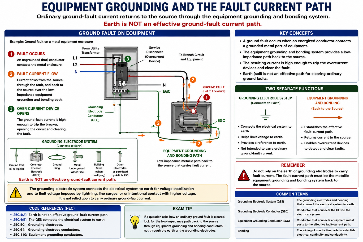
Equipment grounding connects normally non-current-carrying conductive parts of electrical equipment into an effective ground-fault current path. If an ungrounded conductor contacts a metal enclosure, raceway, equipment frame, or other grounded conductive part, the equipment grounding and bonding system provides a conductive path for fault current back toward the electrical source.
For the NASCLA examination, the essential distinction is that equipment grounding is part of the fault-clearing system. Grounding electrodes connect the electrical system to earth, but ordinary ground-fault current must not depend on earth as its effective return path.
The Effective Ground-Fault Current Path
During normal operation, an equipment grounding conductor does not ordinarily carry load current. Its critical function becomes apparent when a ground fault energizes normally non-current-carrying metal equipment. The equipment grounding and bonding system provides a conductive path capable of carrying the resulting fault current back toward the source.
The objective is not merely to connect equipment to earth. The path must have sufficiently low impedance and adequate current-carrying capability to facilitate operation of the circuit overcurrent protective device or other applicable protective equipment.
What Is an Equipment Grounding Conductor?
An equipment grounding conductor, or EGC, is a conductive path that is part of the effective ground-fault current path. It connects normally non-current-carrying metal parts of equipment together and ultimately to the system grounded conductor, grounding electrode conductor, or both at the appropriate source or service bonding point.
The term does not refer only to a green or bare copper wire. NEC 250.118 recognizes multiple wiring methods and conductive components that can serve as equipment grounding conductors when they satisfy the applicable requirements.
The EGC Is a Fault-Current Path
The equipment grounding conductor is not installed simply to place equipment at earth potential. It is part of a deliberately constructed conductive path back toward the electrical source so sufficient fault current can flow to cause the applicable protective device to operate.
What Happens When an Ungrounded Conductor Contacts Metal Equipment?
A Ground Fault Occurs
An energized ungrounded conductor contacts a normally non-current-carrying conductive enclosure, raceway, equipment frame, or other grounded metal part.
The Metal Becomes Part of the Fault Circuit
Because the metal equipment is connected to the equipment grounding and bonding system, the fault establishes a conductive circuit rather than leaving the enclosure electrically isolated.
Fault Current Returns Toward the Source
Current travels through the equipment grounding and bonding path back toward the point where that path is connected to the source grounded conductor or source bonding point.
High Fault Current Flows
The low-impedance fault path permits enough current to flow to facilitate rapid operation of the applicable overcurrent protective device.
The Circuit Is Opened
The circuit breaker or fuse operates and interrupts the faulted circuit, removing the source of energy from the fault.
The Breaker Does Not Trip Because the Equipment Is “Grounded to Earth”
The breaker or fuse operates because sufficient fault current flows through the intentionally constructed conductive fault-current path back to the electrical source. A connection through soil alone normally has too much impedance to be relied upon for this purpose.
Follow the Current Back to Its Source
Electrical current flows in a complete circuit. During a ground fault, the important examination question is therefore not simply, “Where is the equipment grounded?” Instead ask, “What conductive path allows the fault current to return to the electrical source?”
At a grounded service-supplied system, the equipment grounding and bonding path ultimately reaches the service bonding point, where it is connected to the grounded service conductor. This completes the conductive path back through the source winding.
Trace the Complete Fault Loop
For a ground-fault question, begin at the source, follow the ungrounded conductor to the fault, then follow the equipment grounding and bonding path back toward the source. If the proposed path depends primarily on current traveling through soil, reconsider the answer.
Effective Ground-Fault Current Path
Article 250 requires electrical equipment, wiring, and conductive material likely to become energized to be installed in a manner that creates an effective ground-fault current path. The path must have sufficiently low impedance to facilitate operation of the applicable overcurrent protective device or ground detector and must be capable of safely carrying the maximum ground-fault current likely to be imposed on it.
This requirement explains why continuity, proper connections, adequate conductor sizing, and effective bonding are essential parts of equipment grounding.
Why Earth Is Not the Fault-Clearing Path
The NEC specifically states that earth shall not be considered an effective ground-fault current path. Soil resistance and the impedance associated with grounding electrodes generally prevent an earth-only path from carrying the large fault current needed for reliable operation of ordinary branch-circuit or feeder overcurrent protection.
The grounding electrode system remains important for its Article 250 functions, but it should not be substituted for the metallic equipment grounding and bonding path.
Does the Equipment Grounding Conductor Normally Carry Current?
Normal Operation
Load current normally travels on the circuit conductors intended to carry current, not on the equipment grounding conductor.
Ground Fault
The equipment grounding conductor can carry substantial current when an ungrounded conductor faults to grounded metal equipment.
Temporary Current
Fault current should exist only until the protective device clears the fault or another protective function removes the hazardous condition.
Unexpected Current
Continuous current on normally non-current-carrying grounding and bonding paths can indicate an improper neutral-to-ground connection or another wiring problem.
Grounded Conductor and Equipment Grounding Conductor
The grounded conductor, commonly called the neutral in systems where it serves that function, and the equipment grounding conductor have different normal operating functions. The grounded conductor can intentionally carry load current. The equipment grounding conductor normally does not.
They are connected together at specified system bonding locations, but that does not make them interchangeable throughout the electrical distribution system.
Grounded Conductor
A circuit conductor that is intentionally grounded and that can carry normal load current where used as part of the circuit.
Equipment Grounding Conductor
A conductive path connecting equipment into the effective ground-fault current path and normally carrying no load current.
Neutral and Equipment Ground Are Not Interchangeable
Do not assume that a neutral conductor can simply be used as the equipment grounding conductor downstream of the permitted bonding point. Improper downstream neutral-to-ground connections can place normal load current onto metal enclosures, raceways, grounding conductors, and other bonded conductive paths.
What Can Serve as an Equipment Grounding Conductor?
Article 250 recognizes both wire-type equipment grounding conductors and qualifying conductive wiring methods. The exact list and conditions should be checked in 250.118 for the NEC edition used on the examination.
Copper Conductors
Bare, covered, or insulated copper conductors can serve as wire-type equipment grounding conductors when properly sized and installed.
Aluminum Conductors
Aluminum or copper-clad aluminum equipment grounding conductors can be permitted subject to applicable Article 250 restrictions and installation requirements.
Metal Raceways
Specified electrically continuous metal raceway systems can serve as equipment grounding conductors where recognized by 250.118 and properly installed.
Listed Cable Systems
Certain cable armor, metallic sheaths, cable assemblies, cable trays, and other listed wiring methods can provide an equipment grounding path when the NEC conditions are satisfied.
An EGC Is Not Always a Green Wire
A wire-type equipment grounding conductor is common, but qualifying metal raceways and other wiring methods can also provide the equipment grounding path. When a question asks whether an EGC exists, examine the entire recognized wiring method rather than looking only for a separate green conductor.
The Grounding Path Must Remain Continuous
An equipment grounding path is useful only if its electrical continuity is maintained. Loose fittings, improper terminations, missing bonding components, damaged conductors, corrosion, or incompatible connections can increase impedance or interrupt the fault-current path.
Metal raceways used as equipment grounding conductors therefore depend on proper installation of the complete raceway system, including fittings and connections that maintain the required electrical continuity.
Grounding Metal Boxes and Equipment Enclosures
Normally non-current-carrying metal parts that are required to be grounded must be connected into the equipment grounding and bonding system. This can include metal boxes, cabinets, panelboard enclosures, raceways, motor frames, appliance enclosures, and other conductive equipment parts.
The objective is to prevent an isolated conductive enclosure from remaining energized if an internal ungrounded conductor contacts it.
Equipment Grounding Connections
Equipment grounding connections must provide reliable electrical continuity. Connections are made using terminals, grounding screws, listed fittings, bonding jumpers, grounding bushings, clips, or other methods permitted for the particular equipment and wiring method.
Connections must be suitable for the conductor material, enclosure, wiring method, environmental conditions, and fault current that could be imposed.
Do Not Depend on an Unreliable Mechanical Connection
A conductive enclosure can appear mechanically connected while still lacking the electrical continuity required for an effective fault-current path. Article 250 contains specific bonding and grounding provisions for situations where ordinary mechanical connections are not sufficient.
Identifying Wire-Type Equipment Grounding Conductors
Wire-type equipment grounding conductors are commonly bare or identified with green insulation or green insulation with one or more yellow stripes where permitted by the applicable identification requirements. The exact identification rules depend on conductor size and application.
Do not confuse green equipment grounding conductors with grounded circuit conductors, which use the identification requirements applicable to grounded conductors.
Equipment Grounding Conductor Size
Wire-type equipment grounding conductors are generally sized using NEC 250.122 and the rating or setting of the applicable overcurrent protective device ahead of the circuit, subject to the specific rules and exceptions of Article 250.
This differs from grounding electrode conductor sizing. A GEC and an EGC perform different functions and are not selected from the same sizing rules.
GEC and EGC Use Different Sizing Rules
For examination questions, first identify the conductor being sized. Grounding electrode conductors generally lead you toward 250.66 and its associated provisions. Wire-type equipment grounding conductors generally lead you toward 250.122 and its associated provisions.
Equipment Grounding for More Than One Circuit
Article 250 permits a single equipment grounding conductor to serve multiple circuits installed together under specified conditions. When this occurs, the conductor must be sized according to the applicable Article 250 requirements for the circuits involved.
Do not automatically assume that every circuit in a common raceway requires its own separate wire-type equipment grounding conductor.
Equipment Grounding on Motor Circuits
Motor circuits require special attention because branch-circuit short-circuit and ground-fault protective devices can be substantially larger than the motor full-load current. Article 250 contains specific equipment grounding conductor sizing provisions for motor circuits that coordinate with the motor rules of Article 430.
When a NASCLA question combines motors with equipment grounding, identify both the Article 430 protective-device rules and the applicable Article 250 EGC sizing rule before calculating conductor size.
A Ground Rod Does Not Replace an EGC
Connecting equipment to a ground rod does not create the same effective fault-current path as an equipment grounding conductor connected back toward the electrical source. The earth between electrodes is not the low-impedance fault-clearing path required by Article 250.
This is particularly important when considering equipment at separate buildings or structures. A grounding electrode system can be required at the building while an equipment grounding conductor is also required with the feeder or branch-circuit conductors under the applicable rules.
GFCI Protection Is a Different Function
A GFCI detects an imbalance between current leaving and returning through the monitored circuit conductors and can open the circuit at a small ground-fault current. Equipment grounding provides a conductive fault-current path. These are different protective functions.
Where the NEC permits a GFCI-protected replacement receptacle in an existing installation without an equipment grounding conductor, the presence of GFCI protection does not create an equipment grounding conductor that was not already present.
Recognizing Equipment Grounding Problems
Open EGC
A broken or disconnected equipment grounding conductor can leave metal equipment without the intended conductive fault-current path.
Loose Raceway
Loose or improper raceway fittings can compromise continuity where the raceway serves as the equipment grounding conductor.
Improper Neutral Bond
An improper neutral-to-ground connection downstream can place normal neutral current onto equipment grounding and bonded metal paths.
Corrosion or Damage
Corroded connections, damaged conductors, or incompatible materials can increase impedance and reduce the effectiveness of the grounding path.
How to Analyze an Equipment-Grounding Question
Identify What Must Be Grounded
Determine which metal enclosure, equipment frame, raceway, box, or other conductive part is involved.
Identify the Wiring Method
Determine whether the installation uses a wire-type EGC, qualifying metal raceway, cable system, or another method recognized by Article 250.
Check 250.118
Verify whether the proposed conductor or wiring method is recognized as an equipment grounding conductor and whether its conditions are satisfied.
Trace the Fault Path
Follow the conductive path from the equipment back toward the electrical source and verify that the path does not depend upon earth as the effective return path.
Verify Continuity and Bonding
Check fittings, enclosures, connections, bonding jumpers, and other components necessary to maintain an effective conductive path.
Size the EGC
Where a wire-type EGC is involved, apply 250.122 and any specific rules or exceptions that apply to the installation.
Check Equipment-Specific Articles
Determine whether motors, transformers, generators, separate buildings, flexible connections, or other equipment introduce additional grounding or bonding requirements.
Ask What Carries the Fault Current
When several grounding terms appear in the same question, identify the conductor or conductive path that actually carries ordinary ground-fault current back toward the electrical source. This separates equipment grounding and bonding questions from grounding-electrode questions and prevents many common Article 250 errors.
Equipment Grounding
EGC Function
The equipment grounding conductor is part of the effective ground-fault current path and connects normally non-current-carrying conductive equipment parts into that path.
Fault Clearing
A low-impedance grounding and bonding path permits sufficient fault current to flow so the applicable protective device can operate.
250.118
The NEC recognizes multiple conductors and conductive wiring methods that can serve as equipment grounding conductors.
250.122
Wire-type equipment grounding conductor sizing generally begins with the applicable overcurrent protective device and the requirements of 250.122.
Neutral vs. EGC
The grounded conductor can carry normal load current; the equipment grounding conductor normally does not and is not interchangeable with the neutral downstream.
Earth
Earth is not an effective ground-fault current path and a grounding electrode does not substitute for a required equipment grounding conductor.
Leave a Reply
You must be logged in to post a comment.