Back to: NASCLA Master Electrical Contractor Exam Preparation
Service conductors carry electrical energy from the service point to the service disconnecting means, while service equipment provides the main control and cutoff of the utility supply to the premises. Because these components are located at the transition between utility facilities and the premises distribution system, they are subject to specialized installation, protection, grounding, bonding, and equipment requirements.
This lesson examines overhead and underground service conductors, service-entrance wiring methods, service equipment, disconnecting means, conductor protection, and the relationships among meters, disconnects, overcurrent devices, grounding, and bonding. These concepts are central to NEC Article 230 and common NASCLA examination questions.
From the Service Point to the Main Disconnect
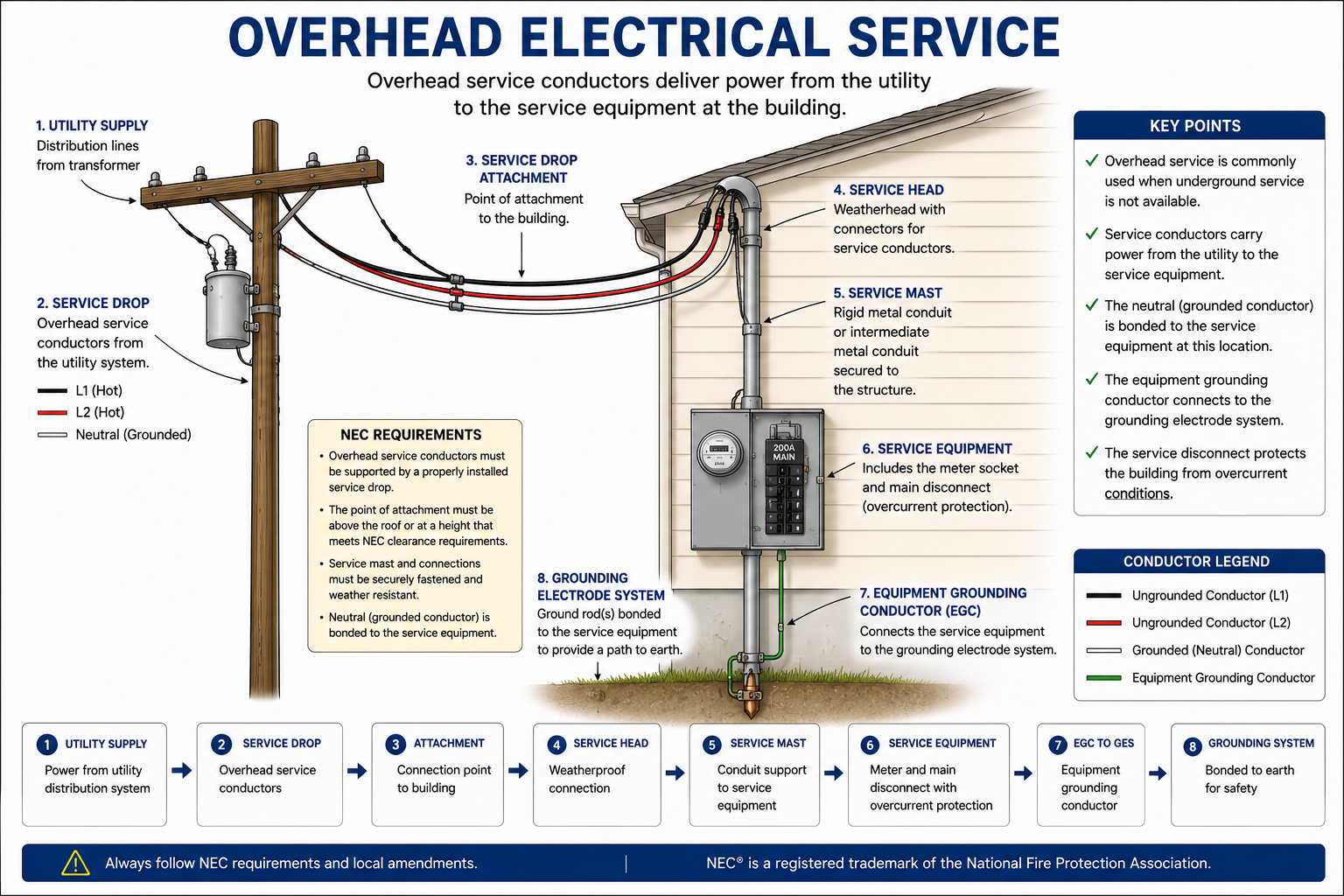
Service conductors are the conductors from the service point to the service disconnecting means. They can be part of an overhead or underground service arrangement and must be installed using wiring methods and equipment suitable for service use and the environmental conditions present.
At the load end of those conductors is the service equipment. Service equipment generally includes one or more circuit breakers, switches, fuses, or associated components that provide the main control and disconnecting means for the supply to the premises.
Service Conductors
Service conductors begin at the service point and extend to the service disconnecting means. Their classification depends on their location in the distribution system rather than simply on whether they are overhead, underground, inside a raceway, or installed as cable.
Service Point
The service point is the connection between the serving utility facilities and the premises wiring. It establishes where the NEC premises wiring begins.
Service Conductors
These conductors extend from the service point to the service disconnecting means and are governed by the applicable service requirements of Article 230.
Service Disconnect
The service disconnecting means provides the principal means of disconnecting the premises wiring from the utility supply.
Load-Side Conductors
Conductors leaving the load side of the service equipment are no longer service conductors. They are typically feeder or branch-circuit conductors depending on the system arrangement.
Identify Both Ends of the Service Conductors
For examination purposes, locate both the service point and the service disconnecting means. The conductors between those two points are service conductors. Once the conductors pass through the service disconnect and associated service overcurrent protection, the downstream wiring is classified differently.
Overhead Service Conductors
An overhead service commonly involves utility conductors extending from a pole or other aerial support to a building or structure. The utility portion and premises portion are separated by the service point.
The premises service-entrance conductors then extend toward the service equipment. Their installation must provide suitable support, weather protection, clearances, protection from physical damage, and fittings appropriate for the wiring method.
Service Drop
The service drop is the overhead utility-side portion extending from the last utility support toward the connection with the premises service-entrance conductors.
Service-Entrance Conductors
For an overhead system, these are the premises service conductors between the service equipment and the point where they connect to the service drop.
Weather Protection
Service raceways and cable entrances exposed to weather require suitable fittings and installation methods that limit moisture entry and protect conductor insulation.
Mechanical Support
The service attachment and associated raceways or cables must be supported and arranged so that mechanical forces from the overhead conductors are safely carried.
Underground Service Conductors
Underground services use conductors or cables installed below grade or through underground raceways from the serving utility toward the service equipment. The service point again determines where utility facilities end and premises service conductors begin.
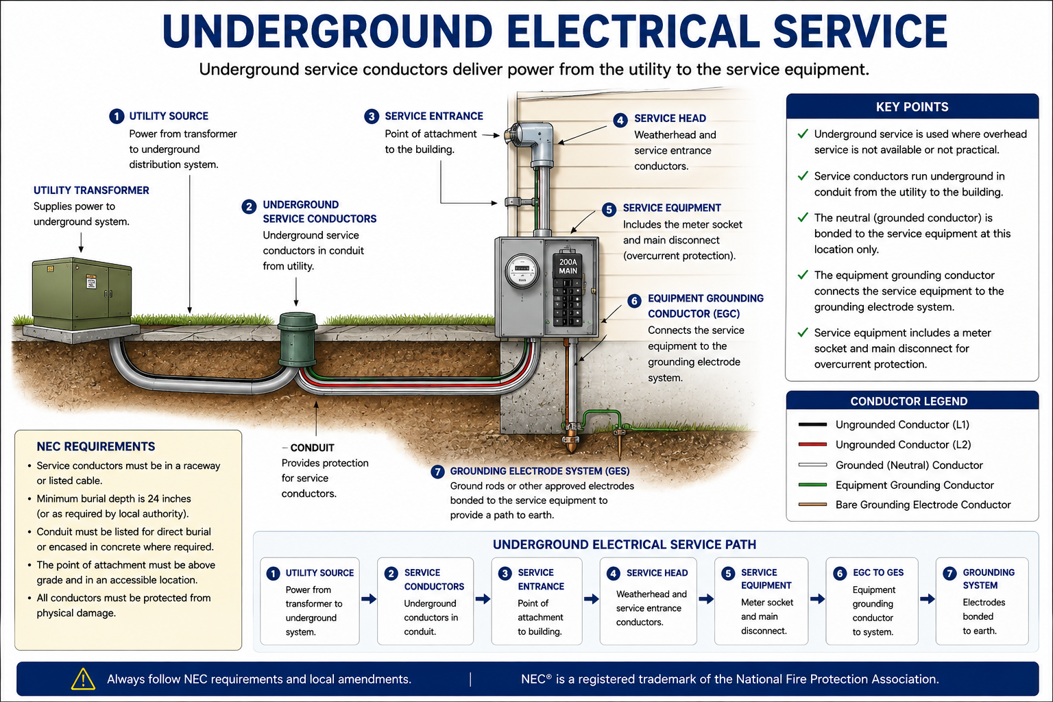
Underground service installations require attention to wiring-method suitability, conductor insulation, wet-location ratings, burial or raceway conditions, physical protection, entrance into equipment, and utility requirements. There is no single universal burial depth for every service installation because the required depth depends on the wiring method and installation conditions.
Do Not Memorize One Burial Depth
Underground wiring depth requirements vary with the wiring method, voltage, location, physical protection, and other conditions. Use the applicable NEC table and notes for the installation shown in the question rather than assuming that every underground service or feeder must be installed at the same depth.
Service-Entrance Conductors and Wiring Methods
Service-entrance conductors can be installed using permitted cable assemblies, raceways, busways, or other wiring methods suitable for the service and location. The wiring method must protect the conductors from physical damage and environmental conditions while maintaining proper separation from other systems where required.
Service conductors are especially important because they are ahead of the premises service disconnect and main overcurrent protection. Their routing within a building is therefore limited so that unprotected service conductors are not unnecessarily extended through the premises.
Keep Unprotected Service Conductors Limited
Service conductors on the line side of the service disconnect are not protected by the premises main overcurrent device. This is one reason Article 230 requires service disconnecting means to be located at a readily accessible location nearest the point of entrance of the service conductors, subject to the applicable Code provisions and local interpretation.
What Qualifies as Service Equipment?
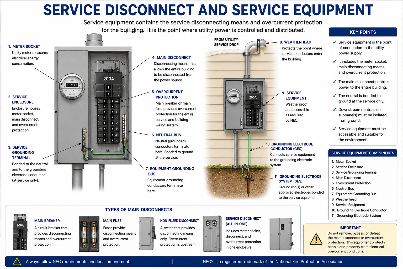
Service equipment is the equipment connected to the load end of the service conductors and intended to constitute the main control and disconnect of the supply. It can consist of circuit breakers, switches, fuses, or combinations of these devices and their associated accessories.
Not Everything Near the Service Is Service Equipment
Equipment should not be classified as service equipment merely because it is physically located near the service entrance. The equipment must perform the function required by the service-equipment definition and be suitable for use as service equipment where that identification is required.
Service Disconnect
A service disconnecting means that forms the main control and cutoff of the supply is part of the service-equipment arrangement.
Main Overcurrent Protection
Service overcurrent protective devices are commonly incorporated with or immediately adjacent to the service disconnecting means as permitted by the applicable installation.
Metering Equipment
A meter socket or meter enclosure is not automatically service equipment solely because it is part of the physical service installation. Its classification depends on its function, construction, listing, and system arrangement.
Downstream Panelboards
Equipment supplied from the load side of the service disconnect is generally feeder-supplied equipment rather than service equipment.
Suitable for Use as Service Equipment
Equipment used as service equipment must be suitable for the application. Service equipment is commonly marked or listed as suitable for use as service equipment, often abbreviated SUSE, where required by the equipment design and installation.
When evaluating an exam question, do not rely only on the physical appearance of the disconnect or panel. Determine whether the equipment is identified for the service function and whether the required bonding and disconnecting provisions are satisfied.
Service Disconnecting Means
The service disconnecting means must be readily accessible and installed at a location permitted by Article 230. A fundamental goal is to provide a practical means of disconnecting the premises wiring while minimizing the length of service conductors routed through the building ahead of the disconnect.
Service disconnecting means must also meet applicable requirements for grouping, identification, ratings, accessibility, and number of disconnects.
Do Not Assume Every Service Has One Main Breaker
Many services use a single main circuit breaker, but Article 230 permits certain service arrangements with multiple service disconnecting means when all applicable conditions are met. Examination questions may therefore show more than one service disconnect without the installation automatically being incorrect.
When multiple disconnects are shown, verify the Code rules governing their number, grouping, location, identification, ratings, and arrangement rather than relying on the simplified idea that every service must contain exactly one main breaker.
Differentiate “Service” from “Service Disconnect”
The service is the conductors and equipment delivering energy from the utility to the premises wiring. The service disconnecting means is one component of that service arrangement. Do not use the two terms interchangeably.
Protecting Service Conductors and Equipment
Service overcurrent protection is coordinated with the service conductor ampacity, calculated load, equipment ratings, and applicable Article 230 requirements. Because the service conductors originate upstream of the premises main protective device, the relationship between service conductors and overcurrent protection differs from ordinary feeder and branch-circuit arrangements.
The service overcurrent protective device generally protects the load-side service equipment and conductors according to the applicable service rules. Additional considerations can apply to parallel conductors, multiple disconnects, fire pumps, motor loads, transformers, and other special installations.
Service Equipment Must Have Adequate Rating
The service equipment must have an ampere rating adequate for the load to be served and must satisfy the applicable minimum ratings required by the Code. The calculated service load, conductor ampacity, and service-equipment rating must therefore be evaluated together.
The service-equipment rating is not automatically determined by the largest individual load. The complete calculated premises load and all applicable demand factors, continuous loads, equipment provisions, and minimum service requirements must be considered.
Bonding at the Service Equipment
At a typical grounded utility-supplied service, the grounded service conductor is bonded to the service equipment enclosure and equipment grounding terminal through the main bonding jumper. This connection establishes the conductive path necessary for ground-fault current to return toward the source.
The grounding electrode conductor connects the service grounding point to the grounding electrode system. The equipment grounding and bonding path and the grounding electrode system perform related but different functions and should not be confused.
EGC and GEC Are Different Conductors
An equipment grounding conductor provides a conductive fault-current path for downstream equipment and wiring. A grounding electrode conductor connects the grounded system or service equipment to the grounding electrode system. Do not label the conductor from the service equipment to the grounding electrodes as an equipment grounding conductor when its function is that of a grounding electrode conductor.
The Service Neutral-to-Enclosure Connection
The main bonding jumper connects the grounded service conductor to the service equipment enclosure and equipment grounding terminal at the service. This bonding connection is essential to the effective ground-fault current path.
Downstream feeder-supplied panelboards generally keep the grounded conductor isolated from equipment grounding conductors and the enclosure. This prevents normal neutral current from flowing on equipment grounding and bonding paths.
Service Equipment Must Withstand the Available Fault Current
Service equipment is installed close to the utility source and can be exposed to substantial available fault current. The interrupting ratings of overcurrent protective devices and the short-circuit current ratings of equipment must be adequate for the available fault current at the point of installation.
This requirement connects the service rules to the fault-current and SCCR concepts introduced earlier in the course. A service disconnect with an inadequate interrupting rating is not made acceptable simply because its ampere rating matches the calculated load.
How to Analyze Service Equipment Questions
Locate the Service Point
Identify where utility facilities end and premises wiring begins.
Trace the Service Conductors
Follow the conductors from the service point to the service disconnecting means.
Identify the Service Equipment
Determine which equipment constitutes the main control and disconnect of the utility supply.
Verify Equipment Suitability
Check whether the equipment is identified and rated for the intended service use.
Check Service Rating and Protection
Compare the calculated load, conductor ampacity, service-equipment rating, and overcurrent-protection requirements.
Check Location and Accessibility
Verify the permitted location, accessibility, grouping, and identification of the disconnecting means.
Verify Grounding and Bonding
Identify the grounded service conductor, main bonding jumper, grounding electrode conductor, equipment grounding connections, and grounding electrode system.
Check Fault-Current Ratings
Verify that the interrupting ratings and equipment short-circuit current ratings are adequate for the available fault current.
Trace the One-Line Diagram Left to Right
For service questions shown as one-line diagrams, begin at the utility source and trace the system toward the load. Identify the service point, service conductors, meter where shown, service disconnect, overcurrent protection, feeders, and downstream panels in order. This prevents service conductors, feeders, and branch circuits from being confused.
Service Conductors and Service Equipment
Service Conductors
Service conductors extend from the service point to the service disconnecting means.
Overhead Service
Overhead service arrangements require proper conductor clearances, attachment, support, weather protection, and suitable service-entrance wiring methods.
Underground Service
Underground service requirements depend on the wiring method, installation conditions, wet-location suitability, physical protection, and applicable burial requirements.
Service Equipment
Service equipment provides the main control and disconnecting means for the serving-utility supply.
Main Bonding Jumper
The main bonding jumper connects the grounded service conductor to the service equipment enclosure and equipment grounding terminal to establish an effective fault-current path.
Fault-Current Ratings
Service overcurrent devices and equipment must have ratings adequate for the available fault current at their point of installation.
Leave a Reply
You must be logged in to post a comment.