Back to: NASCLA Master Electrical Contractor Exam Preparation
Feeders form the electrical distribution path between a power source or service equipment and the final overcurrent protective devices that supply branch circuits. Correctly identifying a feeder is essential because feeder conductor sizing, overcurrent protection, load calculations, grounding, and other requirements differ from those that apply to branch circuits and service conductors.
This lesson explains where feeders begin and end, how they fit into the electrical distribution system, the basic requirements of NEC Article 215, and the systematic process used to identify and analyze feeders on the NASCLA Electrical Contractor examination.
The Middle of the Distribution System
A feeder consists of the circuit conductors between service equipment, the source of a separately derived system or another power supply source, and the final branch-circuit overcurrent protective device. This definition establishes the boundaries that distinguish feeders from service conductors and branch circuits.
In a common installation, a feeder leaves service equipment and supplies a downstream panelboard. The feeder terminates at the final branch-circuit overcurrent devices located in that panelboard, and the conductors leaving those devices become branch-circuit conductors.
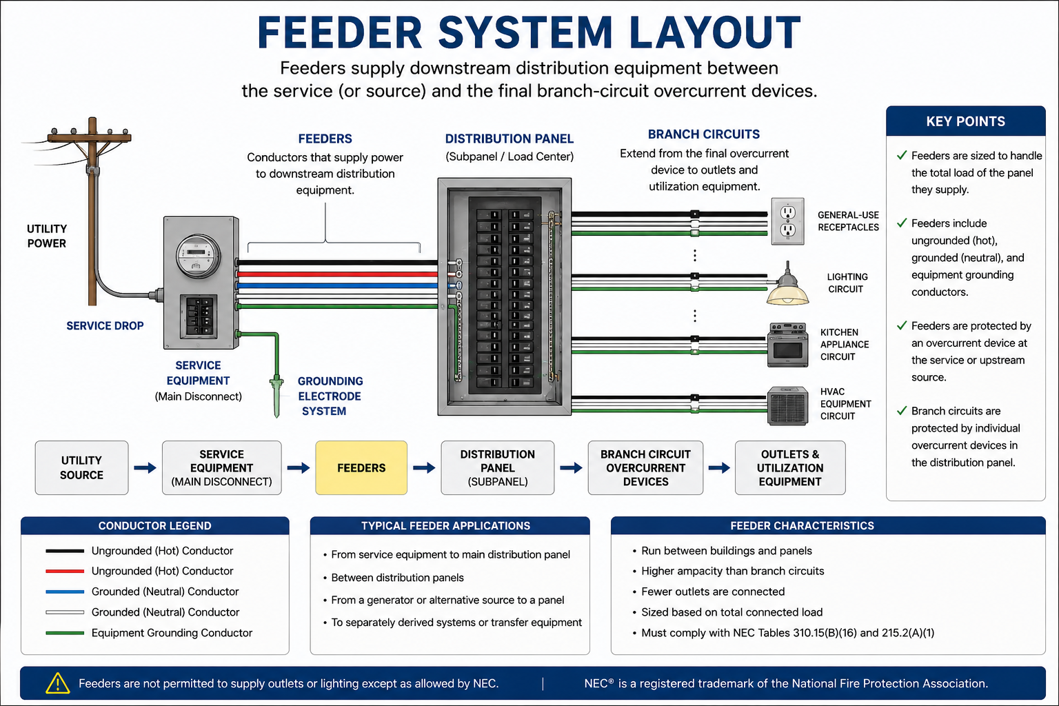
What Is a Feeder?
The feeder definition is based primarily on location within the electrical distribution system. Feeders are located upstream of the final branch-circuit overcurrent protective devices and downstream of service equipment, a separately derived system, or another permitted power source.
Supply End
A feeder can originate at service equipment, a separately derived system such as a transformer, or another power supply source.
Load End
The feeder extends toward the final branch-circuit overcurrent protective devices supplying the downstream branch circuits.
Downstream Distribution
A feeder commonly supplies a panelboard, switchboard, switchgear, motor control center, or other distribution equipment.
Article 215
NEC Article 215 contains the general requirements for feeder installation, conductor ampacity, and protection.
Find the Final Branch-Circuit OCPD
The final branch-circuit overcurrent protective device is the key boundary between a feeder and a branch circuit. Conductors on the supply side of that final device can be feeder conductors, while conductors on its load side supplying outlets are branch-circuit conductors. When examining a one-line diagram, locating this device is often the fastest way to determine which Code rules apply.
Service, Feeder, and Branch Circuit
Many NASCLA questions require you to distinguish between three portions of an electrical distribution system. Although all three carry electrical current, their locations and Code requirements are different.
Service Conductors
Service conductors extend from the service point to the service disconnecting means. They are governed primarily by the service requirements of Article 230 rather than the feeder requirements of Article 215.
Service Equipment
The service equipment provides the main control and disconnecting means at the load end of the service conductors. A feeder commonly begins on the load side of the service equipment overcurrent protection.
Feeder
Feeder conductors distribute power toward downstream equipment containing the final branch-circuit overcurrent protective devices.
Final Branch-Circuit OCPD
The final circuit breaker or fuse protecting a branch circuit marks the transition from feeder distribution to branch-circuit wiring.
Branch Circuit
The branch circuit extends from the final branch-circuit overcurrent protective device to the outlet or outlets supplied by the circuit.
Where Feeders Are Commonly Found
Feeders are used whenever electrical power must be distributed from a source or upstream distribution point to downstream equipment containing branch-circuit overcurrent devices. They appear in residential, commercial, industrial, and institutional electrical systems.
Dwelling Panelboards
A feeder may supply a downstream panelboard serving branch circuits in another portion of a dwelling or associated structure.
Commercial Distribution
Large buildings frequently use feeders between main distribution equipment and panelboards serving individual floors, areas, or groups of loads.
Industrial Systems
Feeders can supply distribution panels, motor control centers, switchboards, switchgear, and other equipment within an industrial distribution system.
Separately Derived Systems
A feeder can originate from a separately derived system such as a transformer and supply downstream distribution equipment.
Conductors in a Feeder
The conductors required in a feeder depend on the electrical system and the loads being supplied. A typical feeder can include ungrounded conductors, a grounded conductor where required, and an equipment grounding conductor.
Ungrounded Conductors
The ungrounded conductors carry electrical energy from the upstream source toward the downstream distribution equipment.
Grounded Conductor
Where the downstream loads require a grounded circuit conductor, the feeder includes a properly sized grounded conductor. Depending on the system, this conductor commonly serves as the neutral.
Equipment Grounding Conductor
Feeders installed on the load side of the service disconnect generally include an equipment grounding conductor or other permitted equipment grounding path to provide an effective ground-fault current path.
Raceway or Cable
Feeder conductors must be installed using a wiring method permitted for the location and installation conditions.
Do Not Rebond the Neutral in a Typical Downstream Panel
In a typical feeder-supplied downstream panelboard, the grounded conductor is isolated from the equipment grounding conductors and the metal enclosure. The equipment grounding conductor is bonded to the enclosure and provides the intended equipment grounding and fault-current path. Reconnecting the grounded conductor to the enclosure downstream of the service or applicable system bonding point can place normal neutral current on equipment grounding paths.
Feeder Conductors Must Carry the Calculated Load
Feeder conductor sizing begins with the load supplied by the feeder. The calculated feeder load is determined using the applicable requirements of Article 220 and any other Code provisions that apply to the loads being served.
For a feeder supplying continuous and noncontinuous loads under the general Article 215 rule, conductor sizing must account for 100 percent of the noncontinuous load plus 125 percent of the continuous load unless an applicable permitted alternative or exception changes the requirement.
Continuous and Noncontinuous Loads
A continuous load is a load where the maximum current is expected to continue for three hours or more. Recognizing continuous loads is important because they can affect the minimum required feeder conductor ampacity and overcurrent protection.
Noncontinuous Load
Under the general sizing method, include 100 percent of the calculated noncontinuous load.
Continuous Load
Under the general sizing method, include 125 percent of the continuous load when determining the applicable minimum feeder conductor ampacity.
Basic Feeder Load Calculation
Assume a feeder supplies 80 amperes of noncontinuous load and 40 amperes of continuous load. Under the general 125-percent continuous-load method, the minimum calculated ampacity before considering other applicable requirements is determined as follows:
Noncontinuous Portion
80 A × 100% = 80 A
Continuous Portion
40 A × 125% = 50 A
Calculated Requirement
80 A + 50 A = 130 A
The calculation establishes a required ampacity of at least 130 amperes under this basic example. Selecting the actual conductor requires continuing through the applicable conductor ampacity, terminal temperature, adjustment, correction, and other Code requirements.
Calculated Load Is Not Automatically the Breaker Size
A calculated feeder load is part of the process used to determine conductor and overcurrent-protection requirements. Do not automatically convert a calculated load directly into a circuit-breaker size without checking the applicable conductor ampacity, standard overcurrent-device ratings, equipment ratings, special load requirements, and any permitted exceptions.
Protecting Feeder Conductors
Feeders require overcurrent protection in accordance with the applicable NEC requirements. The protective device must be coordinated with the ampacity of the feeder conductors and any rules applicable to the equipment and loads being supplied.
The feeder overcurrent protective device is normally located at the point where the feeder conductors receive their supply. However, the NEC contains specific permissions for feeder taps and other arrangements that can allow conductors to be installed under defined conditions without overcurrent protection directly at their supply point.
Do Not Apply Branch-Circuit Rules Automatically
A feeder and a branch circuit may use conductors of the same size and may be protected by similar circuit breakers, but their Code requirements are not interchangeable. First determine whether the conductors are a feeder or a branch circuit, and then use the article and rules applicable to that portion of the electrical system.
An Important Feeder Exception
The general rule is that conductors are protected against overcurrent in accordance with their ampacity. The NEC also contains specific feeder-tap provisions that permit certain conductors to be supplied from an overcurrent device whose rating exceeds the ampacity of the tap conductors when all conditions of the applicable tap rule are satisfied.
Feeder-tap questions require careful Code navigation. Do not rely on a memorized distance or conductor ratio without identifying which tap provision applies, because different conditions apply to different installations.
Feeder Voltage Drop
Voltage drop can become significant on long feeder runs. NEC informational guidance has traditionally identified approximately 3 percent voltage drop on the feeder or branch circuit and approximately 5 percent total feeder-plus-branch-circuit voltage drop to the farthest outlet as providing reasonable operating efficiency for many power, heating, and lighting loads.
For examination purposes, distinguish informational voltage-drop guidance from mandatory requirements that may apply to particular installations or equipment. When a voltage-drop calculation is requested, carefully identify conductor length, load current, conductor material, system voltage, and whether the problem involves a single-phase or three-phase circuit.
How to Analyze a Feeder Question
Identify the Conductors
Use the distribution diagram and Article 100 definitions to verify that the conductors in question are actually feeder conductors.
Identify the Loads
Determine every load supplied by the feeder and classify the loads as required for the applicable load calculation.
Calculate the Feeder Load
Use Article 220 and any applicable equipment articles to determine the calculated load supplied by the feeder.
Determine Minimum Ampacity
Apply Article 215 requirements, including the applicable continuous-load provisions and any other requirements affecting minimum conductor ampacity.
Select and Verify Conductors
Use the applicable Article 310 conductor ampacity requirements and verify terminal temperature limitations, adjustment factors, correction factors, and other installation conditions.
Determine Overcurrent Protection
Verify the permitted feeder overcurrent protective device and determine whether any special rules, tap provisions, or equipment requirements apply.
Check Grounding and Bonding
Verify the required equipment grounding conductor, grounded-conductor treatment, bonding, and downstream panel configuration.
Identify the Circuit Before Doing the Math
Do not begin a conductor-sizing calculation until you know whether the conductors are service conductors, feeder conductors, or branch-circuit conductors. Correct arithmetic applied to the wrong NEC article still produces the wrong examination answer.
Feeder Fundamentals
Feeder Boundary
A feeder is located between service equipment, a separately derived system or another supply source, and the final branch-circuit overcurrent protective device.
Article 215
Article 215 provides the general NEC requirements governing feeder installation, conductor ampacity, and protection.
Calculated Load
Feeder sizing begins with the loads supplied and the applicable load-calculation requirements.
Continuous Loads
The general feeder-sizing method accounts for 125 percent of continuous load plus 100 percent of noncontinuous load, subject to applicable permitted alternatives and exceptions.
Overcurrent Protection
Feeder conductors require properly coordinated overcurrent protection, with specific Code provisions available for feeder taps and other permitted arrangements.
Grounding and Bonding
A typical feeder-supplied downstream panel keeps the grounded conductor isolated from the enclosure and equipment grounding system while maintaining an effective equipment grounding path back toward the source.
Leave a Reply
You must be logged in to post a comment.