Introduction to Battery Energy Storage Systems
Adding battery energy storage changes a PV system from a relatively simple generation system into a system that can generate, store, convert, transfer, and deliver electrical energy through several different operating paths. The battery may charge from solar, discharge to support loads, interact with the utility grid, and provide selected loads with power during an outage.
For the service technician, the first objective is not to diagnose the battery itself. It is to identify the installed system, understand how energy normally moves through it, determine which equipment controls that movement, and recognize which electrical sources can remain present during inspection and troubleshooting.
Battery Storage Changes How the PV System Operates
A grid-connected PV system without storage normally has a straightforward power path. The PV array produces DC power, an inverter converts that energy to AC, and the resulting power supplies building loads or is exported through the utility connection.
Battery storage adds another source and another destination for energy. Power can be directed into the battery during charging and returned from the battery during discharge. Depending on the system design, battery power may support normal loads, reduce utility consumption, respond to utility programs, or supply designated loads when utility power is unavailable.
Identify the System Before Troubleshooting It
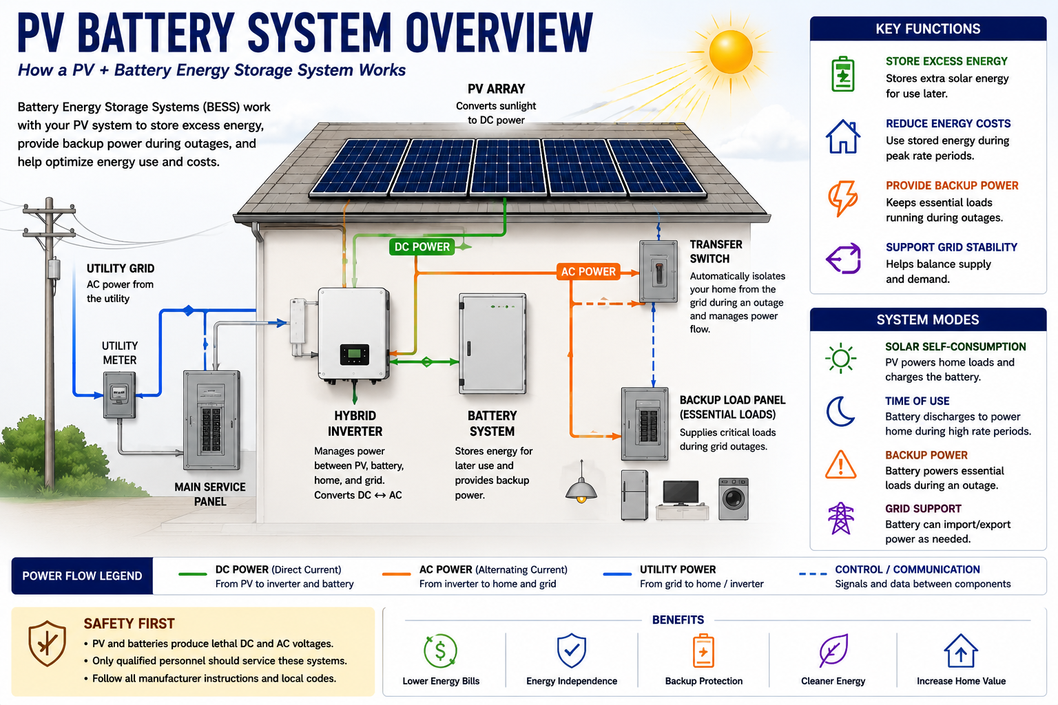
Battery systems vary significantly between manufacturers and product generations. Two installations that provide the same basic backup function may use very different equipment arrangements and power paths.
Before taking measurements, determine what equipment is installed and how it is interconnected. Identify the PV system, battery equipment, inverter or power-conversion equipment, transfer or backup equipment, disconnects, distribution panels, communications devices, and utility connection.
Technician principle: Do not assume the power path from the appearance of the battery enclosure. Trace the installed system and identify the actual equipment architecture.
Store Energy Now and Make It Available Later
The basic purpose of an energy-storage system is simple: electrical energy is converted into a form that can be stored in the battery and later converted back into usable electrical power.
The equipment required to accomplish this function depends on the system architecture. Some batteries contain integrated power electronics, while other systems use external inverters or hybrid power-conversion equipment.
Charge
Electrical energy is directed into the battery and stored for later use.
Store
The battery retains energy within its available operating state-of-charge range.
Discharge
Stored battery energy is converted into electrical power that can support connected loads or other permitted system functions.
Control
System electronics determine when charging and discharging are permitted and how power should move through the installation.
Power and Energy Are Different
Battery systems are commonly described using both power and energy ratings. These values describe different capabilities.
Power, normally expressed in kilowatts (kW), describes how rapidly the system can deliver or absorb electrical energy at a particular time. Energy, normally expressed in kilowatt-hours (kWh), describes how much electrical energy the battery can store or make available over time.
Example: A battery may contain enough stored energy to operate a load for several hours but still be unable to start or support that load if its required instantaneous power exceeds the battery system’s output capability.
How Much Usable Energy Is Currently Stored?
Battery systems commonly report state of charge, or SOC, as a percentage. This provides the technician with an indication of the battery’s present stored-energy condition.
A low state of charge does not automatically indicate a failed battery. The system may intentionally maintain reserve capacity, may not have had sufficient energy available for charging, may be operating according to a schedule, or may be prevented from charging by another system condition.
Likewise, a battery displaying a high state of charge does not by itself prove that the system can successfully provide backup power. Power-conversion equipment, transfer equipment, controls, communications, and load configuration must also operate correctly.
The Battery Is More Than a Collection of Cells
Modern battery systems use electronic battery-management functions to monitor and control battery operation. Depending on the equipment, these functions can monitor cell voltage, current, temperature, state of charge, operating limits, and other battery conditions.
The battery-management system may limit or stop charging or discharging when operating conditions move outside permitted limits. A battery that is not charging or discharging therefore should not automatically be diagnosed as having failed cells.
Troubleshooting implication: A battery can be electrically capable of storing energy while the control system intentionally prevents charging or discharging because another required condition is not satisfied.
First Determine How the Battery Is Coupled to the PV System
One of the most useful early distinctions is whether the battery system is AC coupled or DC coupled. This tells the technician where major power conversion occurs and helps establish the expected power path during charging and discharging.
Do not use these terms merely as equipment labels. They describe how the storage system is electrically integrated with the PV generation system.
The PV System and Battery System Meet on the AC Side
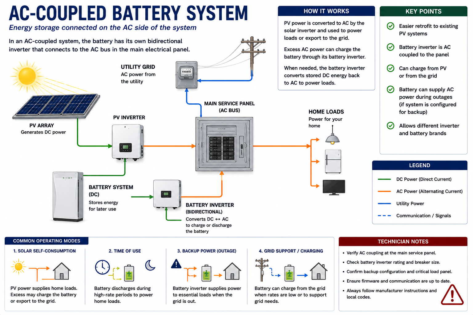
In an AC-coupled system, the PV array typically operates through its PV inverter, while the battery uses separate bidirectional power-conversion equipment. The two systems are interconnected on the AC side.
During solar production, PV DC power is converted to AC by the PV inverter. When that energy is used to charge the battery, the battery system converts the appropriate AC power back into the form required for battery charging. During battery discharge, the battery’s power electronics convert stored energy back to AC for use by the system.
Separate PV Generation From Battery Operation
One advantage of understanding the AC-coupled architecture is that the technician can often evaluate the PV generation system and battery storage system as separate functional sections.
If the PV system produces normal AC power but the battery does not charge, the problem may be associated with battery power conversion, controls, communications, configuration, available charging conditions, or the battery itself rather than the PV array.
If the battery operates but PV generation is absent, the technician can follow the PV troubleshooting procedures developed earlier in this course without immediately assuming that the storage system caused the generation problem.
PV Generation and Battery Storage Share DC-Side Equipment
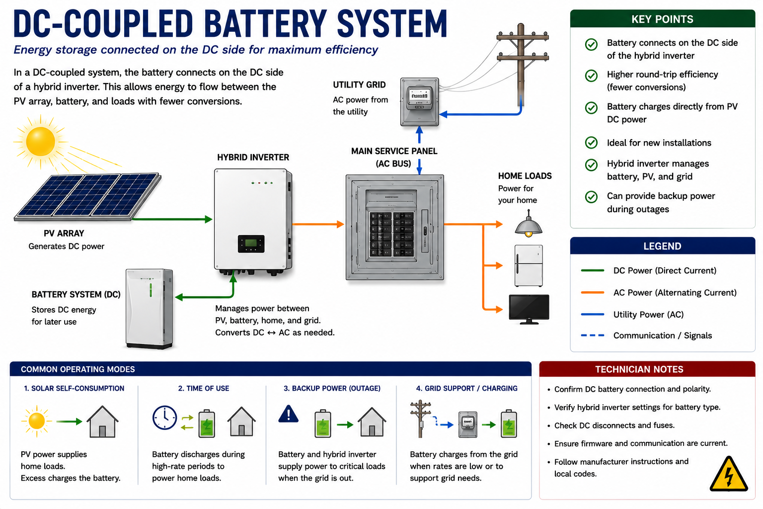
In a DC-coupled system, PV generation and battery storage are integrated on the DC side through compatible power-conversion equipment, often using a hybrid inverter or related architecture.
PV energy can be directed toward battery charging before final conversion to AC for building loads or grid interaction. During battery discharge, stored DC energy is converted to AC through the system’s power-conversion equipment.
Shared Equipment Creates Shared Failure Points
Because PV generation and battery storage may share power-conversion equipment, a fault in a hybrid inverter, common DC bus, control system, or related equipment can affect both functions.
The technician should therefore avoid treating every charging problem as a battery problem or every production problem as a PV-array problem. Determine which functions are operating and which are not, then identify the equipment common to the failed functions.
Diagnostic clue: When several system functions fail at the same time, look for equipment or controls those functions have in common.
Why the Difference Matters in the Field
Power Path
The coupling method determines where PV power and battery power meet within the electrical system.
Test Locations
The architecture determines which AC and DC locations provide useful diagnostic measurements.
Shared Equipment
DC-coupled systems may have more shared conversion equipment, while AC-coupled systems often provide clearer separation between PV and battery conversion.
Fault Isolation
Knowing the architecture helps determine whether a fault is likely associated with generation, storage, conversion, controls, or distribution.
The Utility Normally Establishes the AC Electrical System
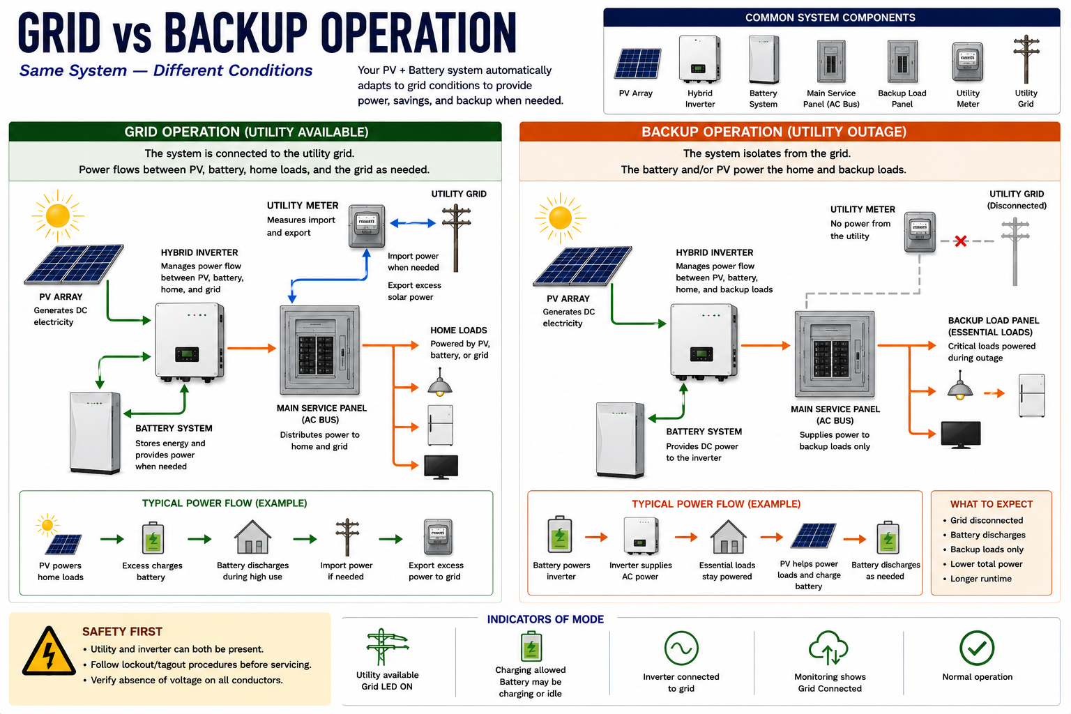
During normal grid-connected operation, the utility source is present and the storage system operates according to its configured control strategy. PV power may supply building loads, charge the battery, or be exported where permitted. Battery power may support loads, reduce grid consumption, or remain in reserve.
The exact operating strategy depends on system configuration, battery state of charge, available PV production, load demand, utility requirements, schedules, and user-selected operating modes.
A Battery System Does Not Necessarily Back Up the Entire Building
When utility power is lost, the storage system must separate the backed-up electrical system from the utility before intentionally energizing those circuits. Transfer or isolation equipment performs this function as part of the system design.
Some installations supply only a dedicated backup-load panel. Others may support a larger portion of the electrical system or use load-management equipment to control which circuits can operate during an outage.
The Same Installation Can Have Two Very Different Operating States
Grid Present
The utility is available, the system remains interconnected according to its normal operating mode, and PV and battery power operate within the configured grid-connected strategy.
Grid Lost
The backup system must recognize the outage and isolate the supported circuits from the utility.
Backup Established
The battery inverter or other grid-forming equipment establishes the electrical source for the backed-up loads.
Grid Returns
The system must detect acceptable utility conditions and complete the required transition before returning to normal grid-connected operation.
Utility Outage Does Not Mean the Backup Panel Is De-Energized
A properly operating battery backup system is specifically designed to energize selected circuits when utility power is absent. The loss of utility voltage can therefore cause one portion of the building electrical system to become de-energized while another portion remains energized from the battery system.
Technicians must identify the backup boundaries and energy sources before assuming the electrical condition of any panel or circuit.
The Battery System May Establish the Backup AC Source
A conventional grid-connected PV inverter normally follows an existing AC source. During an outage, backup-capable storage equipment may establish the voltage and frequency required by the backed-up electrical system.
This grid-forming function allows compatible PV equipment and loads to operate within the isolated backup system when the equipment design and available energy permit it.
For troubleshooting, this means that loss of backup power can involve more than battery state of charge. The technician may need to evaluate power conversion, transfer equipment, system controls, communications, load demand, and other conditions required to establish the backup source.
Stored Energy Does Not Guarantee Every Load Can Operate
A battery can have significant stored energy while still having a limited maximum power output. Large motors, compressors, electric heating equipment, pumps, EV charging, and other high-demand loads may exceed the capability of the storage system or may be intentionally excluded from backup operation.
When investigating a backup complaint, determine which loads are supposed to be supported before deciding that the system has failed.
The System May Be Doing Exactly What It Was Configured to Do
Battery systems can use different operating strategies. Depending on the manufacturer and configuration, the system may prioritize backup reserve, self-consumption, time-based energy use, utility programs, or another control objective.
A battery that does not discharge while the utility is present may therefore be operating normally. Likewise, a battery may intentionally stop charging before reaching the percentage a technician expects because of reserve settings, temperature limits, system controls, or another configured condition.
Before diagnosing abnormal battery behavior, identify the configured operating mode.
Battery Systems Depend Heavily on Information Exchange
Modern storage systems rely on communications between batteries, power-conversion equipment, gateways, meters, current sensors, transfer equipment, monitoring platforms, and other devices.
These communications allow the system to determine power flow, battery limits, utility status, load demand, and operating commands. A communications failure can therefore create symptoms that appear to be electrical or battery failures.
Later lessons will treat communications as a separate diagnostic path rather than assuming that every missing device or unavailable function represents failed power hardware.
Battery Systems Change the Safety Assumptions
A PV-plus-storage installation can contain utility AC, PV-generated DC, battery DC, inverter-generated AC, and stored energy within equipment. Different portions of the system can remain energized from different sources.
Opening the utility main does not necessarily remove battery-generated AC from backed-up circuits. Opening the PV disconnect does not remove stored battery energy. Turning the battery system off does not necessarily remove utility voltage or illuminated-array voltage from other equipment.
Service principle: Identify each source independently. Do not use the status of one source to assume the condition of another.
One Symptom Can Have Several Possible Causes
Without storage, a complaint such as no PV production can often be approached by following the AC and DC paths around the inverter. With storage, the technician may also need to consider charging logic, battery limits, transfer equipment, communications, metering, backup configuration, operating mode, and load behavior.
Battery Not Charging
Could involve PV generation, grid availability, conversion equipment, battery state, controls, communications, settings, or operating limits.
No Backup Power
Could involve battery charge, inverter operation, transfer equipment, backup configuration, load demand, controls, or communications.
Battery Offline
Could represent a battery fault, shutdown condition, communications problem, disconnect position, or system-level control condition.
Low Runtime
Could involve available battery energy, load demand, reserve settings, battery condition, temperature, or customer expectations.
Build a System Map
Before beginning battery troubleshooting, identify enough of the installation to describe how power should move through it.
Identify the PV Architecture
Determine whether the system uses a string inverter, microinverters, optimizers, hybrid equipment, or another configuration.
Identify the Battery System
Record manufacturer, model, quantity of battery units, and major associated equipment.
Determine AC or DC Coupling
Establish where PV generation and battery storage connect within the system.
Identify Transfer Equipment
Determine how the system isolates backed-up loads from the utility during an outage.
Identify Backup Loads
Determine which circuits are intended to operate from battery power.
Identify Disconnects
Locate utility, PV, battery, inverter, and other disconnecting means associated with the installed equipment.
Identify Communications and Metering
Locate gateways, meters, current sensors, communications wiring, and other devices used to control or monitor power flow.
Manufacturer Information Becomes More Important With Storage
Battery systems are highly manufacturer-specific. Shutdown sequences, service modes, fault indications, communications architecture, allowable measurements, commissioning procedures, and restoration sequences can differ substantially.
Record equipment model information and obtain the appropriate service documentation before beginning invasive testing or disconnecting battery equipment.
Do Not Treat a Battery as Just Another DC Source
Battery energy-storage equipment contains substantial stored energy and may present electrical, thermal, chemical, fire, and mechanical hazards depending on the battery technology and equipment design.
Do not open battery enclosures, bypass protective devices, disconnect internal battery components, or perform measurements beyond the equipment’s intended field-service procedures. Follow manufacturer instructions and applicable electrical safe-work requirements.
Lesson 19 will address battery-system hazards, visual inspection, disconnects, abnormal conditions, and situations in which the technician should stop work rather than continue testing.
What You Should Take From This Lesson
Storage Adds Another Energy Path
Energy can move into the battery during charging and return from the battery during discharge.
Power and Energy Are Different
kW describes the rate at which power can be delivered, while kWh describes stored energy available over time.
Identify AC or DC Coupling
The coupling architecture helps establish the power path, useful test locations, and shared equipment.
Grid and Backup Operation Are Different
During an outage, transfer equipment isolates supported circuits and compatible storage equipment establishes power for the backup system.
Not Every Load Is Necessarily Backed Up
Determine which circuits the system was designed to support before diagnosing a backup-power complaint.
Operating Mode Matters
A battery may charge, discharge, or remain idle because of configuration rather than because of a fault.
Communications Matter
Storage equipment depends on information from multiple devices, so communications faults can imitate power-system failures.
Identify Every Energy Source
Utility, PV, and battery sources must be considered independently during service work.
Map the System Before Testing
Identify the architecture, battery equipment, transfer equipment, backup loads, disconnects, metering, and communications before beginning diagnosis.
Battery Components and Power Flow
The next lesson moves deeper into the installed battery system. It identifies the major components and traces energy during battery charging, battery discharge, normal grid-connected operation, and utility-outage backup operation.
Battery Energy Storage Systems
Return to the Part V landing page for the complete battery energy-storage lesson sequence.