Battery Components and Power Flow
Battery energy-storage systems contain more than a battery. They combine energy storage, power-conversion equipment, disconnects, controls, communications, metering, transfer equipment, and electrical distribution to move energy between the PV system, battery, utility, and building loads.
For the service technician, understanding these components and their relationships is essential. Before troubleshooting a charging or backup problem, the technician should be able to trace where power should come from, where it should go, which equipment controls that path, and which components are common to several operating modes.
Learn the Components, Then Follow the Energy
A battery system can operate differently depending on sunlight, building load, battery state of charge, utility availability, operating mode, and system configuration. The same conductors and equipment may carry power in different directions at different times.
The technician therefore needs two kinds of information before beginning diagnosis: what each component does and how energy should move through those components in the operating condition being investigated.
Identify the Equipment by Function
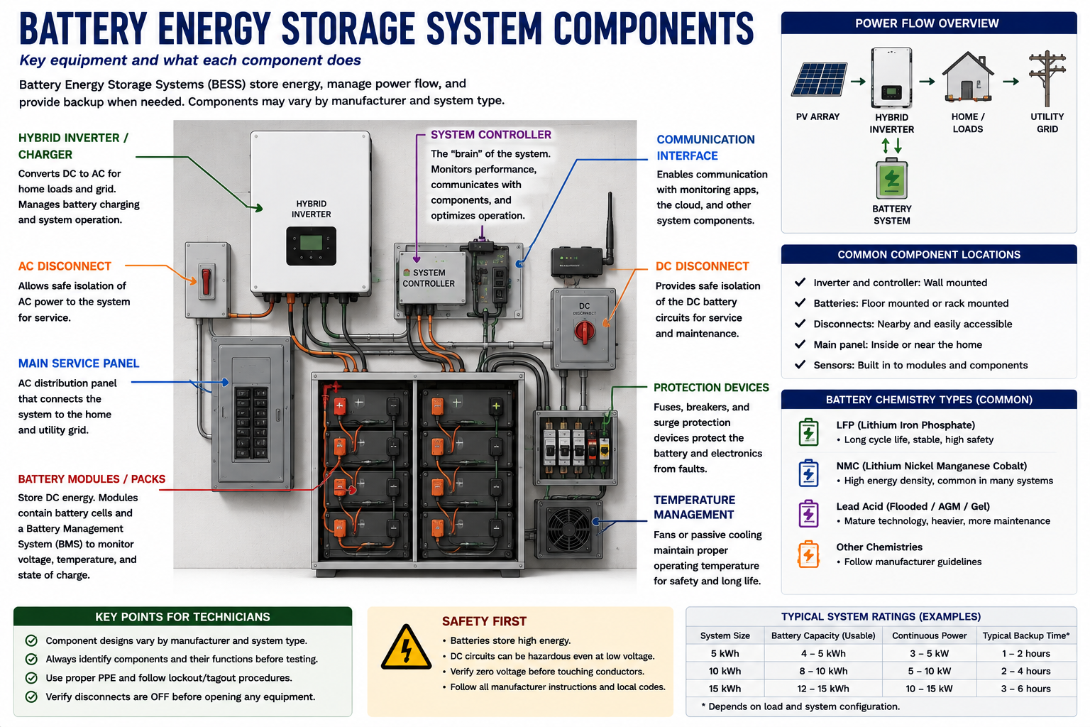
Battery installations vary by manufacturer, but most systems contain equipment that performs the same basic functions. Some products combine several functions into one enclosure, while other systems use separate components.
PV Array
Converts sunlight into DC electrical energy. Depending on the system architecture, that energy may travel through a string inverter, module-level electronics, or hybrid power-conversion equipment.
Battery
Stores electrical energy for later use and includes protective and battery-management functions appropriate to the equipment design.
Power-Conversion Equipment
Converts electrical power between the forms required by the battery, PV system, AC electrical system, and loads. The equipment may be separate or integrated into a hybrid inverter or battery assembly.
Transfer or Isolation Equipment
Separates the backup electrical system from the utility during an outage and establishes the permitted power path for backup operation.
Metering and Sensors
Measure power flow so the control system can determine utility import or export, load consumption, PV production, and battery charging or discharging.
Communications and Controls
Exchange information between batteries, inverters, meters, gateways, transfer equipment, monitoring systems, and other devices.
Energy Storage Includes Internal Control and Protection
The battery enclosure may contain individual cells assembled into modules or packs along with sensors, contactors, protective devices, and battery-management electronics. The exact internal architecture is manufacturer-specific.
For routine field troubleshooting, the battery should normally be treated as an integrated piece of equipment rather than as individual cells to be accessed and tested internally.
The technician should use the manufacturer’s available status information, approved external test points, fault information, disconnects, and diagnostic procedures rather than opening areas that are not intended for field service.
The BMS Protects and Controls Battery Operation
The battery-management system, commonly called the BMS, monitors conditions required for safe battery operation. Depending on the equipment, this can include cell or module voltage, battery current, temperature, state of charge, operating limits, and internal fault conditions.
The BMS can limit or stop charging and discharging when conditions move outside permitted limits. This distinction becomes important during troubleshooting because a battery that is not accepting or delivering power may be intentionally protected rather than electrically failed.
Diagnostic principle: “Battery not charging” describes a symptom. It does not establish that the battery itself is defective.
Energy Must Be Converted in Both Directions
A battery stores DC energy, while most building loads and utility connections operate on AC. Battery systems therefore require power electronics capable of transferring energy between these electrical systems.
During charging, power-conversion equipment directs energy toward the battery in the form required for storage. During discharge, stored battery energy is converted into usable AC power.
In AC-coupled systems, this function is commonly associated with separate battery power-conversion equipment. In DC-coupled systems, battery and PV functions may be incorporated into common hybrid equipment.
Power Can Move Through the Same Equipment in Opposite Directions
A conventional PV inverter is primarily associated with moving energy from the PV array toward the AC system. Battery power conversion must often operate bidirectionally.
During one operating condition, power moves toward the battery. Later, the direction reverses and power moves away from the battery toward connected loads.
This means that current direction is an important part of battery-system diagnosis. A current measurement without understanding the expected direction of power flow can be misleading.
The Control System Must Know Where Power Is Going
Battery controls often depend on current transformers, meters, or other sensors installed at specific locations within the electrical system. These measurements allow the system to determine whether the building is importing power, exporting power, consuming PV production, or charging or discharging the battery.
Incorrect sensor orientation, incorrect conductor placement, lost communications, configuration errors, or failed metering can cause the control system to make incorrect decisions even though the main power equipment is functional.
Technician clue: When measured power flow does not agree with what the monitoring system reports, include metering and sensor configuration in the diagnostic process.
Trace Energy Toward the Battery
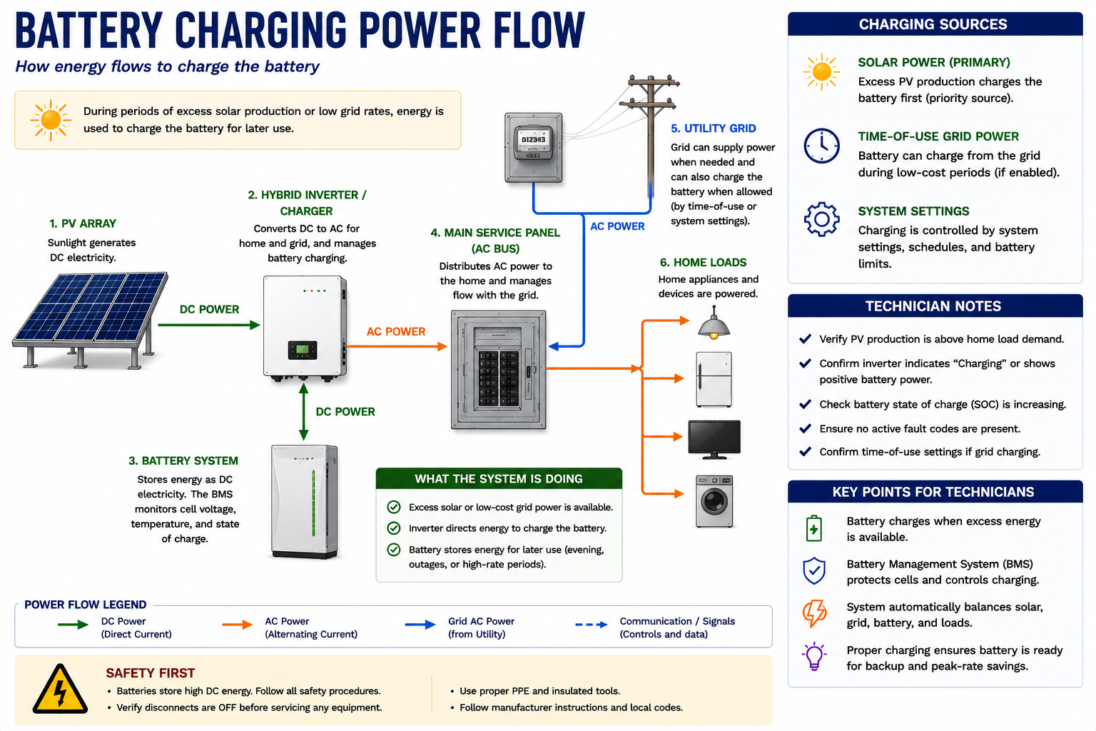
When the battery is charging, electrical energy must originate from an available source, pass through the required conversion and control equipment, and reach the battery under conditions that permit charging.
The exact path depends on whether the system is AC coupled or DC coupled, but the diagnostic principle is the same: start with the available source and follow the expected power path toward the battery.
Several Conditions Must Be Satisfied Before Charging Occurs
Energy Available
The configured charging source must have energy available. Depending on the system, this may be PV production, utility power, or another permitted source.
Battery Can Accept Charge
The battery state of charge, temperature, BMS status, and operating limits must permit charging.
Conversion Equipment Available
The inverter or other power-conversion equipment must be operating and capable of transferring power toward the battery.
Controls Permit Charging
Operating mode, schedules, reserve settings, utility programs, or other control logic must call for charging.
Communications Available
Required devices must be able to exchange battery status, limits, commands, and system measurements.
Electrical Path Complete
Disconnects, conductors, protective devices, connections, and other equipment in the charging path must be in the required condition.
Do Not Start With the Battery When the Complaint Is “Not Charging”
First determine whether charging should be occurring under the current operating mode and system conditions. Then determine whether energy is available and follow the charging path toward the battery.
The fault may be generation, conversion, metering, communications, configuration, wiring, protective equipment, or battery related.
Available Solar Power Must First Satisfy the System’s Operating Logic
A PV-plus-storage system does not necessarily direct all available solar power into the battery. Building loads may consume some or all of the available PV production. Export limits, reserve settings, battery state of charge, and operating mode can further affect the amount available for charging.
For example, if PV production is 4 kW while building loads consume 3 kW, only a portion of the PV production may remain available for battery charging under a self-consumption strategy.
Some Systems Can Charge From the Utility
Depending on equipment, configuration, utility requirements, and operating mode, a battery system may be capable of charging from the utility grid.
Therefore, observing battery charging when PV production is low does not necessarily indicate incorrect operation. Likewise, a system that does not charge from the grid may be intentionally configured or restricted from doing so.
Verify the installed system’s permitted charging sources before interpreting the behavior.
Trace Energy Away From the Battery
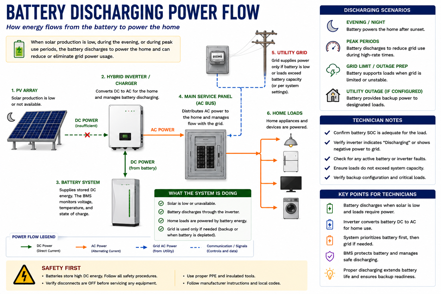
During discharge, the direction of energy flow reverses. Stored energy leaves the battery, passes through the required power-conversion equipment, and becomes available to the AC electrical system or designated loads.
A Charged Battery Does Not Automatically Discharge
Battery discharge depends on system operating logic. The battery may remain idle even at a high state of charge if the system is maintaining backup reserve, waiting for a scheduled period, responding to utility requirements, or operating in a mode that does not presently call for discharge.
When a customer reports that the battery “isn’t being used,” first determine whether the configured operating mode should be commanding discharge.
Battery Power Can Reduce Utility Import
In a self-consumption operating strategy, excess PV energy can be stored rather than exported. Later, when building demand exceeds PV production, the battery can discharge to reduce the amount of power imported from the utility.
The resulting power flow changes continuously as PV production, load demand, and battery condition change.
This is normal operation and demonstrates why a single instantaneous measurement may not describe the complete behavior of the system.
Backup Operation Changes the Power Path
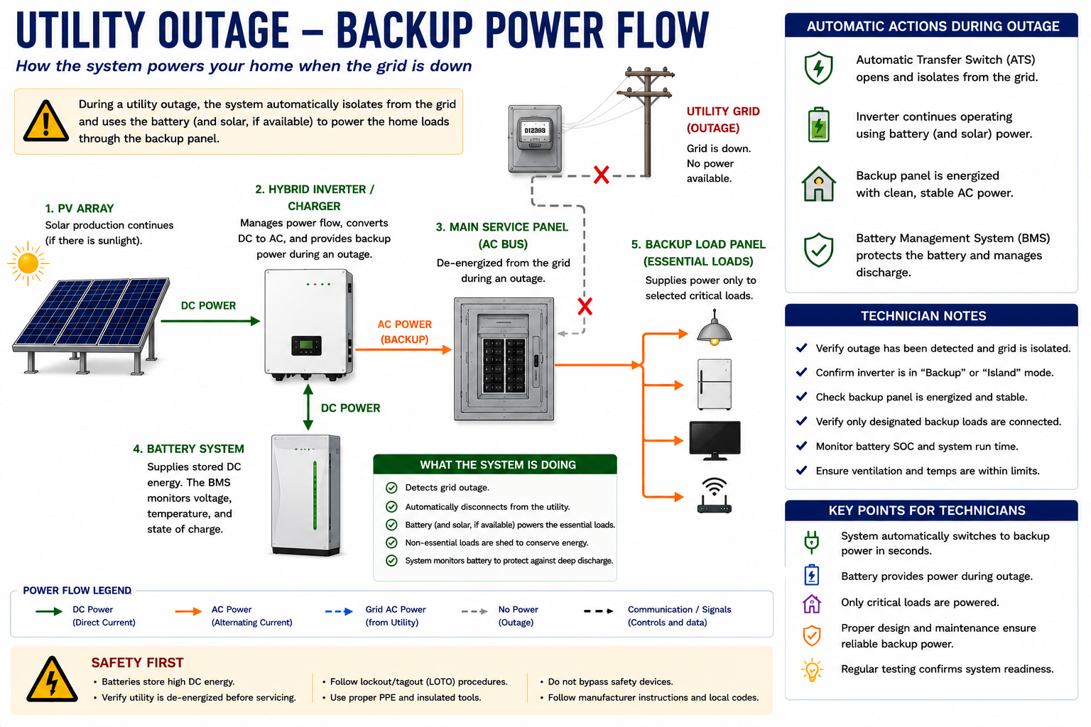
When utility power is lost, a backup-capable battery system must detect the outage and isolate the supported electrical system from the utility. Once the required isolation has occurred, compatible storage equipment can establish the AC source for the backed-up loads.
The power path during this condition is different from normal grid-connected operation and should be understood before attempting to troubleshoot a backup complaint.
Backup Requires Several Functions to Work Together
Utility Power Is Lost
The system detects that acceptable grid voltage or frequency is no longer present.
Utility Is Isolated
Transfer or isolation equipment prevents the backup source from energizing the utility connection.
Backup Source Is Established
Compatible battery power-conversion equipment establishes the AC electrical source for the backup system.
Battery Supplies Loads
Stored energy is converted and delivered to the circuits included in the backup system.
Compatible PV May Continue Operating
Depending on the system architecture and operating conditions, PV generation may contribute power to the isolated backup system and potentially recharge the battery.
Something Must Establish Voltage and Frequency
Most grid-connected PV inverters normally operate by following an existing AC electrical source. When the utility is unavailable, backup-capable battery equipment may establish the voltage and frequency reference for the isolated electrical system.
This function is commonly described as grid forming. It allows compatible loads and, where supported, PV generation equipment to operate without the utility grid being present.
If the battery has energy but backup power is absent, the technician must consider whether the system successfully detected the outage, isolated the utility, established the backup source, and connected the appropriate loads.
Identify Which Loads Are Actually Supported
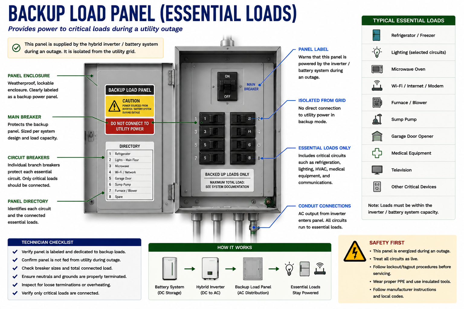
Many battery installations do not provide backup power to every circuit in the building. Instead, selected circuits are supplied through a dedicated backup or essential-load panel.
Do Not Diagnose a Design Choice as a System Failure
During an outage, a receptacle, air conditioner, electric range, EV charger, or other load may lose power simply because that circuit was never included in the backup system.
Before troubleshooting a reported loss of backup power, determine whether the affected circuit is actually intended to receive battery power.
First question during a backup complaint: Is this load supposed to be backed up?
The Battery Has a Power Limit
The total connected load must remain within the operating capability of the battery and power-conversion equipment. A system may have substantial stored energy but still be unable to support excessive instantaneous load.
Large motors, compressors, pumps, resistance heating, cooking equipment, and other high-demand loads can produce operating or starting requirements that exceed available backup power.
Some systems use load-control equipment to automatically disconnect or prevent operation of selected loads when backup capacity is limited.
Solar Generation May Still Contribute — If the System Supports It
In compatible PV-plus-storage systems, the battery equipment can establish the isolated AC environment required for PV generation to continue during an outage. PV power can then support loads and potentially recharge the battery.
However, this capability depends on the architecture and manufacturer design. Do not assume that every PV system paired with a battery can continue generating during a grid outage.
Generation and Load Must Remain Balanced
During grid-connected operation, excess PV power may be exported to the utility where permitted. During isolated backup operation, that external destination is no longer available.
The system must therefore control PV generation based on load demand, battery charging capability, state of charge, and other operating limits. When the battery is full and loads are low, PV production may be reduced or stopped as part of normal system control.
Important: Reduced PV production during backup operation does not automatically indicate a PV fault. The system may be intentionally limiting generation because there is nowhere for the excess energy to go.
The System Must Transition Back to Grid Operation
When utility power returns, the battery system does not simply connect two independent AC sources together without control. The system must detect acceptable utility conditions and complete its required reconnection process.
The exact sequence and delay are manufacturer-specific. After reconnection, loads return to their normal supply arrangement and the battery system resumes its configured grid-connected operating strategy.
Use Power Flow as a Diagnostic Tool
Many battery-system complaints become easier to understand when the technician stops thinking first about individual components and instead asks where power should be flowing.
Battery Not Charging
Start at the expected charging source and follow the path toward the battery.
Battery Not Discharging
Determine whether discharge is being commanded, then follow the path from the battery toward the loads.
No Backup Power
Follow the sequence from utility-loss detection through isolation, backup-source establishment, and the backup distribution system.
One Backup Load Missing
Determine whether the complete backup system is down or whether the problem is isolated to the individual branch circuit or load.
Find the Last Point Where Operation Is Normal
When tracing a power-flow problem, identify the last component or test point where the expected condition exists and the first point where it does not.
The fault is often located in the equipment, conductors, controls, communications, or protective devices between those two points.
Look for Components Shared by Several Functions
Some equipment participates in charging, discharging, and backup operation. A failure in shared equipment can therefore produce several symptoms at the same time.
For example, if a battery neither charges nor discharges and backup operation is also unavailable, consider what equipment or control functions are common to all three conditions before assuming several independent failures occurred simultaneously.
Control Information Is Part of the Power-Flow System
Physical conductors carry electrical power, but communications determine whether much of that power is allowed to move. Batteries and power-conversion equipment may exchange operating limits, state-of-charge information, temperature information, commands, and fault status.
Meters and current sensors provide information about building consumption and utility power flow. Transfer equipment communicates utility and backup status. Gateways may coordinate the complete installation.
A communication failure can therefore interrupt an otherwise electrically intact power path.
Trace the Actual Installation
Before electrical troubleshooting, locate the equipment and establish how it relates to the power-flow diagrams.
Locate PV Generation
Identify the array and the equipment that converts PV power.
Locate the Battery
Identify all battery units and their external disconnecting means where provided.
Locate Power Conversion
Identify the battery inverter, hybrid inverter, integrated power electronics, or other conversion equipment.
Locate Transfer Equipment
Determine which equipment separates the backup system from the utility.
Locate the Backup Distribution
Identify the backup panel or other distribution arrangement supplying supported loads.
Locate Metering
Identify system meters and current sensors and determine what conductors they measure.
Locate Communications Equipment
Identify gateways, controllers, communications wiring, network connections, and other control components.
Power Flow Can Change Without a Technician Moving a Disconnect
Battery systems are automatically controlled. Charging can begin, discharge can begin, PV output can change, and the system can transition between grid and backup operating modes as conditions change.
Do not assume that a conductor remains in the same electrical state because it was measured earlier. Identify all possible energy sources, follow the manufacturer’s service procedures, and establish the required electrical condition before accessing or working on equipment.
What You Should Take From This Lesson
Identify the Major Components
Recognize the battery, power-conversion equipment, transfer equipment, metering, communications, PV generation, and electrical distribution.
Understand Bidirectional Power
Energy moves toward the battery during charging and away from the battery during discharge.
Trace Charging From the Source
Determine whether energy is available and follow the expected path toward the battery.
Trace Discharge Toward the Loads
Determine whether discharge is commanded and follow battery energy through conversion equipment toward the electrical load.
Understand Backup Power Flow
Utility isolation and establishment of a backup AC source are required before the battery can safely supply designated loads during an outage.
Know the Backup Boundaries
Determine which circuits are actually intended to receive battery power before diagnosing a backup complaint.
Metering and Communications Matter
Incorrect measurements or lost communications can prevent normal operation even when the major power components remain functional.
Follow the Power
Find the last point where operation is normal and the first point where the expected condition disappears.
Battery Safety and Visual Inspection
The next lesson moves from system operation to field inspection. It develops a systematic battery inspection sequence, identifies major hazard areas and disconnects, compares normal and abnormal battery conditions, and establishes conditions that should cause the technician to stop work rather than continue testing.
Battery Energy Storage Systems
Return to the Part V landing page for the complete battery energy-storage lesson sequence.