PV Repair, Replacement, and Final Documentation
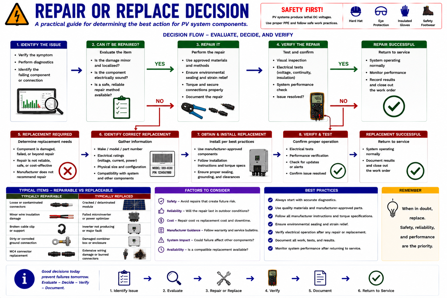
Once the fault has been identified, the technician must decide whether the problem can be repaired in the field or whether the affected component should be replaced. Wiring and connector problems may often be repairable when the damage is localized and the repair can restore the circuit to an approved condition. Inverters, microinverters, optimizers, damaged modules, and other electronic components are more commonly replaced as assemblies.
This lesson focuses on practical service decisions: determining what can be repaired, identifying the information required to obtain the correct replacement, dealing with older equipment and module compatibility, restoring the system, verifying the repair, and creating complete final service documentation.
Repair the Circuit When Appropriate — Replace the Component When Necessary
Not every PV fault should be handled the same way. A damaged conductor, failed connector, loose termination, or other localized wiring problem may be repairable when the technician can restore the circuit using the correct materials, tools, and approved procedures.
Electronic equipment such as string inverters, microinverters, power optimizers, and internally damaged PV modules generally requires replacement rather than internal field repair. The service decision should be based on the component type, extent of damage, manufacturer requirements, availability of parts, system compatibility, and the ability to verify the completed work.
Begin With the Type and Extent of the Fault
The first service decision is whether the damaged condition can be restored to an acceptable condition without replacing the entire component.
Localized Conductor Damage
May be repairable by replacing the damaged conductor section or cable assembly when the repair method and materials are appropriate for the installation.
Connector Damage
May be repairable by replacing the affected connector pair or cable assembly using compatible components and the correct crimping and assembly procedure.
Loose or Damaged Termination
May be repairable when the conductor and terminal remain suitable for service and the connection can be restored according to manufacturer requirements.
Internal Electronic Failure
Inverters, optimizers, microinverters, and similar power electronics generally require assembly replacement rather than component-level field repair.
Damaged PV Module
Cracked glass, internal cell damage, severe delamination, burned junction boxes, or other major module damage usually requires module replacement.
Severe Enclosure Damage
Equipment that can no longer maintain its required environmental or electrical protection may require complete replacement.
Do Not Repair a Component Beyond Its Intended Service Scope
The fact that equipment can physically be opened does not mean that internal component repair is appropriate. Manufacturer service procedures, warranty requirements, certification, environmental sealing, internal high-voltage components, and replacement-part availability all affect the service decision.
Field repair should restore the installation to a reliable and approved condition, not create an improvised substitute for the original equipment design.
PV Connectors Require Correct Parts and Correct Assembly
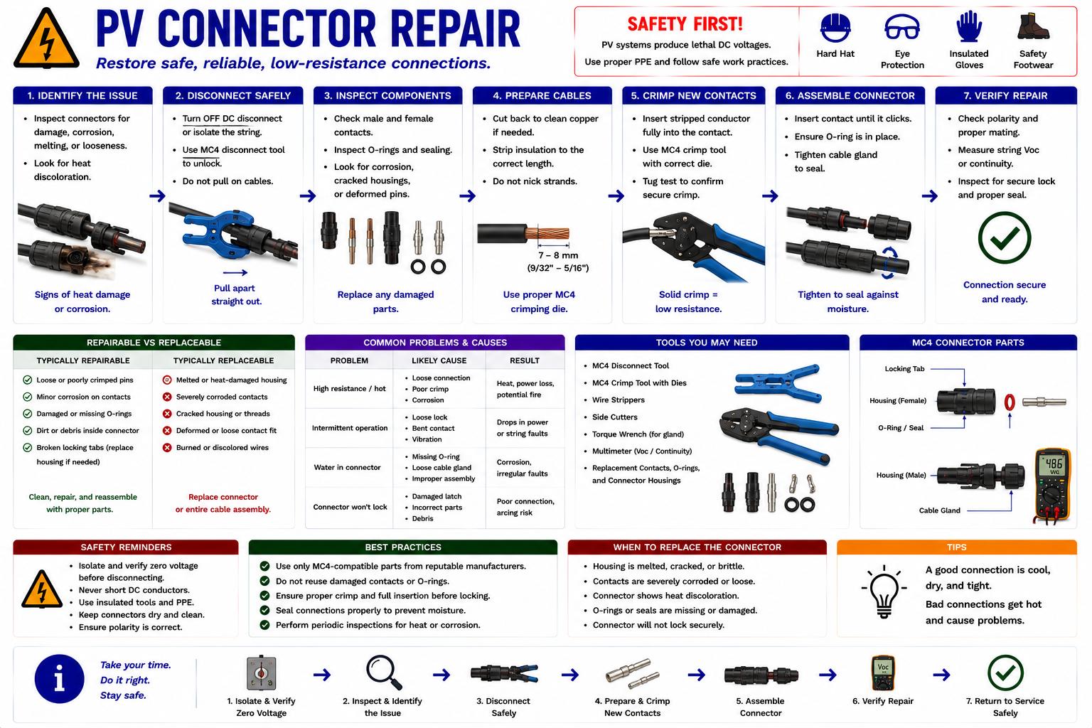
PV connector problems are common enough that technicians should understand the difference between a proper connector repair and an improvised splice. A connector that has overheated, melted, cracked, corroded, or suffered contact damage should be evaluated as part of the complete connection.
When replacement is permitted, use compatible connector components, the correct contacts, properly sized conductor, approved stripping dimensions, correct crimp tooling, required sealing components, and the proper final assembly procedure.
Similar-Looking Connectors May Not Be Approved to Mate
Connector families from different manufacturers can look very similar. Physical fit alone does not establish compatibility.
A replacement connector should be selected according to the manufacturer and system requirements. Mixing incompatible connector types can produce poor contact pressure, sealing problems, increased resistance, heating, and eventual arcing or failure.
Do not repair a burned connector by simply installing whichever connector happens to fit. Identify the connector system before replacing the damaged parts.
The Electrical Contact Is Created During Assembly
The conductor-to-contact crimp is a critical electrical connection. An improper crimp can create excessive resistance even when the connector looks normal from the outside.
Use the specified crimp tool and die for the connector and conductor being installed. Verify conductor preparation, insertion depth, contact retention, polarity, seal condition, and final connector engagement.
Do Not Stop at the Failed Connector
If a connector overheated, determine why. Look for cable strain, incomplete engagement, incompatible connector halves, contamination, corrosion, poor crimping, unsupported wiring, water exposure, or another condition that contributed to the failure.
The replacement should not be returned to the same condition that caused the original connector to fail.
An Inverter Replacement Requires More Than Matching Kilowatts
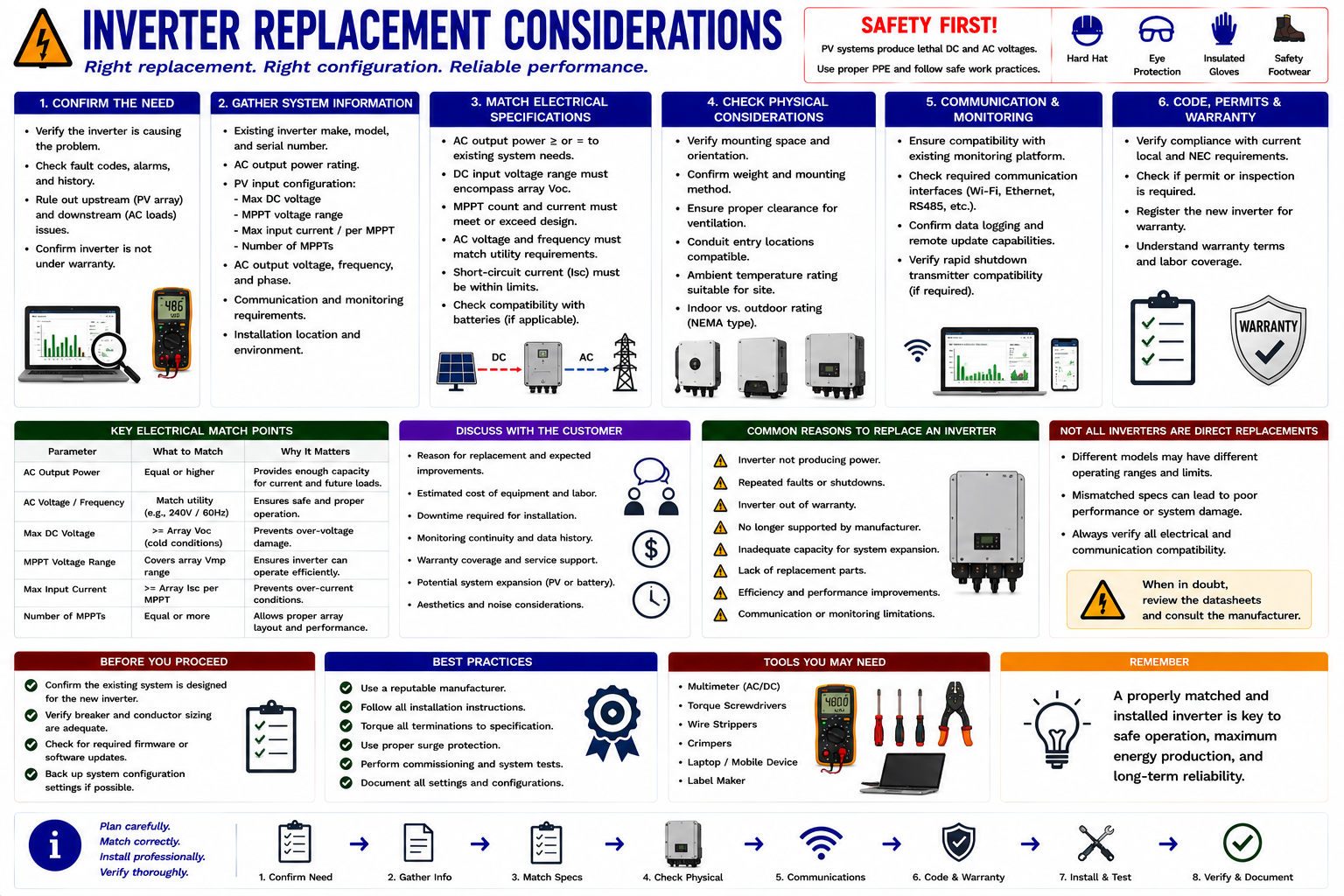
A failed string inverter may no longer be available in the original model. Selecting a replacement requires review of both the PV array and the AC system.
Check the DC Side
Maximum DC Voltage
The replacement inverter must be suitable for the maximum possible string voltage under the installation’s operating conditions.
MPPT Operating Range
The string operating voltage must fall within an appropriate maximum-power-point tracking range.
DC Input Current
The inverter inputs must be capable of handling the current from the connected strings.
Number of Inputs
Verify that the replacement supports the existing string and MPPT configuration or determine what approved system changes are required.
Check the AC Side
AC Voltage
The inverter must be appropriate for the building electrical system.
Phase Configuration
Single-phase and three-phase equipment are not interchangeable without considering the complete system design.
Output Current
Verify the relationship between inverter output, conductors, breakers, disconnects, and interconnection equipment.
Grid Requirements
The replacement must meet the applicable utility and grid-interactive requirements for the installation.
Physical and Digital Compatibility Matter Too
Mounting dimensions, wiring-entry locations, disconnect arrangements, communications equipment, monitoring platforms, rapid-shutdown compatibility, optimizers, batteries, gateways, firmware, commissioning tools, and internet connectivity may all affect the replacement.
A technically compatible inverter may still require significant installation modifications when it differs from the original equipment.
Identify the Exact Device and System Generation
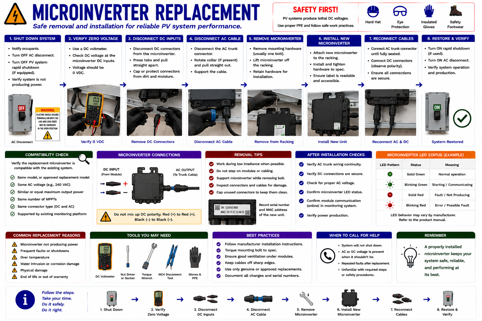
Microinverter systems can remain in service for many years, during which manufacturers may introduce several generations of equipment. A current replacement device may not be a direct substitute for an older microinverter.
Record Before Ordering the Replacement
Manufacturer and Model
Identify the existing device and determine what replacement models the manufacturer supports.
PV Module Information
Verify that the replacement microinverter is suitable for the electrical characteristics of the connected module.
AC Branch
Confirm AC voltage, branch-circuit arrangement, cabling, connectors, and system generation.
Communications
Determine whether the replacement device will communicate with the existing gateway or monitoring platform.
Mounting
Confirm that the replacement can be mounted correctly beneath the array with suitable clearances and conductor routing.
Commissioning
Determine whether the replacement requires device registration, pairing, firmware updates, array-map changes, or other setup.
Older Arrays Can Be Difficult to Match
PV modules are manufactured in rapidly changing product generations. Years after an array is installed, the exact original module may no longer be available.
Replacing one damaged module therefore requires a comparison of electrical characteristics, physical dimensions, mounting geometry, connector requirements, and appearance rather than simply finding a module with approximately the same wattage.
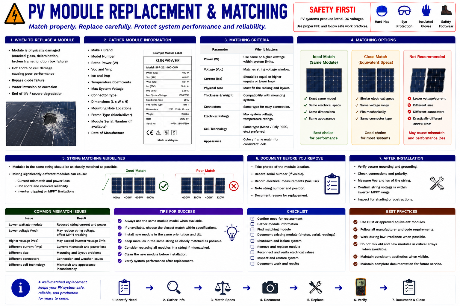
Compare More Than Rated Watts
Pmax
Compare the replacement module’s rated power with the original array.
Voc
Open-circuit voltage affects maximum string voltage and must be considered with the series configuration.
Vmp
Operating voltage should be compatible with the electrical behavior of the existing string and inverter.
Isc
Short-circuit current affects circuit and protective-device considerations.
Imp
Maximum-power current is particularly important in a series string because the modules share the same operating current path.
Maximum System Voltage
The replacement module must be suitable for the voltage class of the existing PV system.
The Lowest-Performing Module Can Affect the String
Modules in a series string carry the same current. Installing a replacement module with substantially different electrical characteristics can affect the operation of the string even if the replacement’s wattage rating appears acceptable.
Use manufacturer guidance and system design information when matching a replacement into an existing string.
New Modules Are Often Different Sizes
Modern modules frequently produce more power from larger or differently proportioned frames than modules installed many years earlier. A new module can therefore have suitable electrical characteristics and still be difficult to install in the existing array.
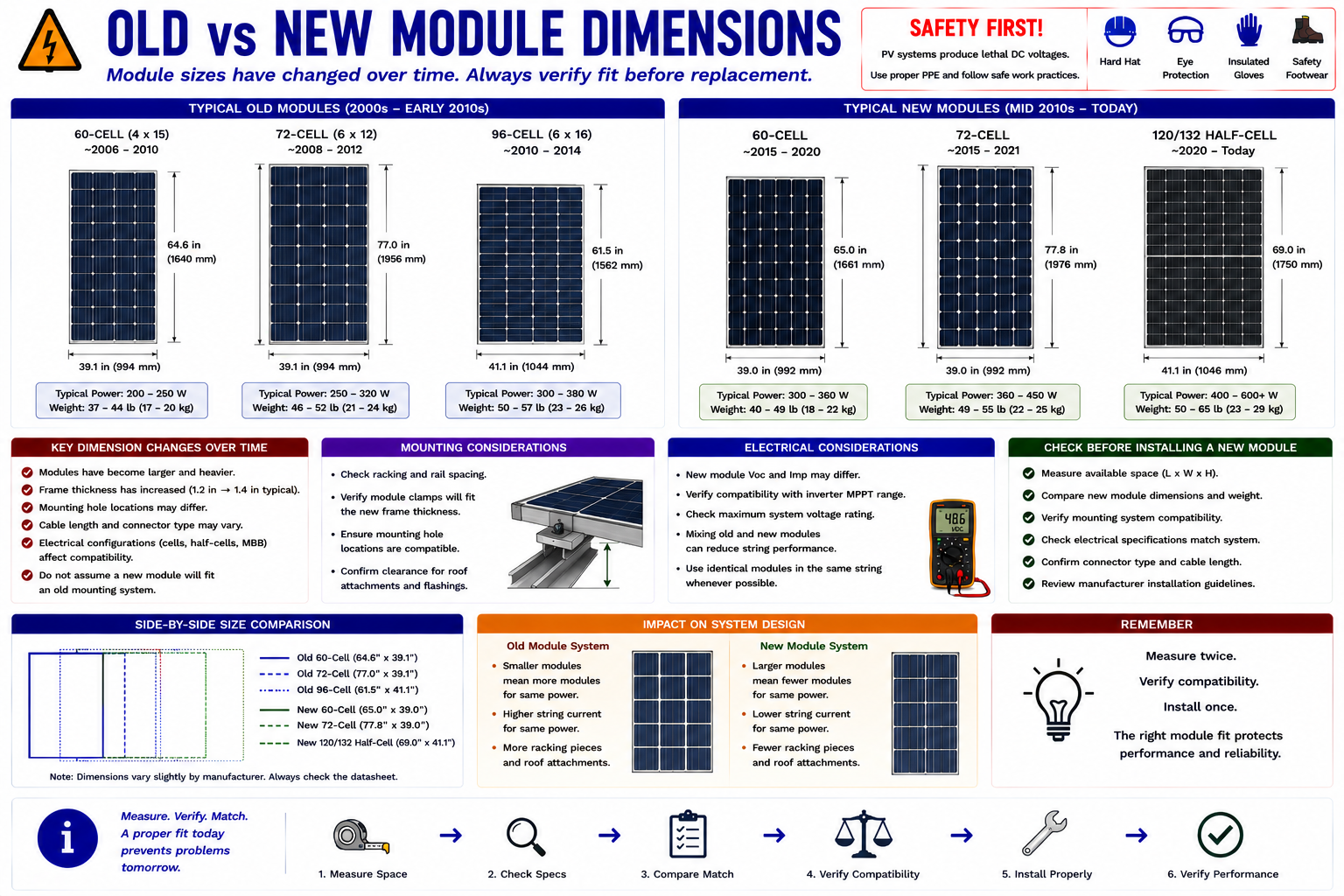
Measure Before Ordering
Overall Length and Width
The replacement must physically fit within the available array space.
Frame Thickness
Different frame depths can affect clamp compatibility and array alignment.
Clamp Zones
Verify the manufacturer’s permitted clamping locations and whether they align with the existing mounting rails.
Junction Box Location
Different junction-box placement can affect conductor reach and routing beneath the module.
Lead Length
Confirm that module leads can reach the required connection points without excessive tension or unsupported extensions.
Connector Type
Connector compatibility must be resolved without creating unapproved mixed connections.
Document the Replacement Decision
If an identical replacement cannot be obtained, document the original module specifications and the proposed replacement specifications. Record why the replacement was selected and any modifications required to install it properly.
Some arrays may require relocation of modules, mounting changes, compatible adapter hardware, different string arrangements, or another engineered solution rather than simply placing the new module in the original opening.
Restore the System Methodically
Once the repair or replacement is complete, inspect the work before restoring power. Check conductor routing, connector engagement, polarity, mounting hardware, torque, grounding and bonding, equipment covers, seals, labeling, and any other condition affected by the repair.
Restore the system according to the required manufacturer and site-specific startup sequence.
Repeat the Measurement That Identified the Problem
A completed repair is not verified simply because the system turns on. Return to the evidence that established the original fault and confirm that the abnormal condition has been corrected.
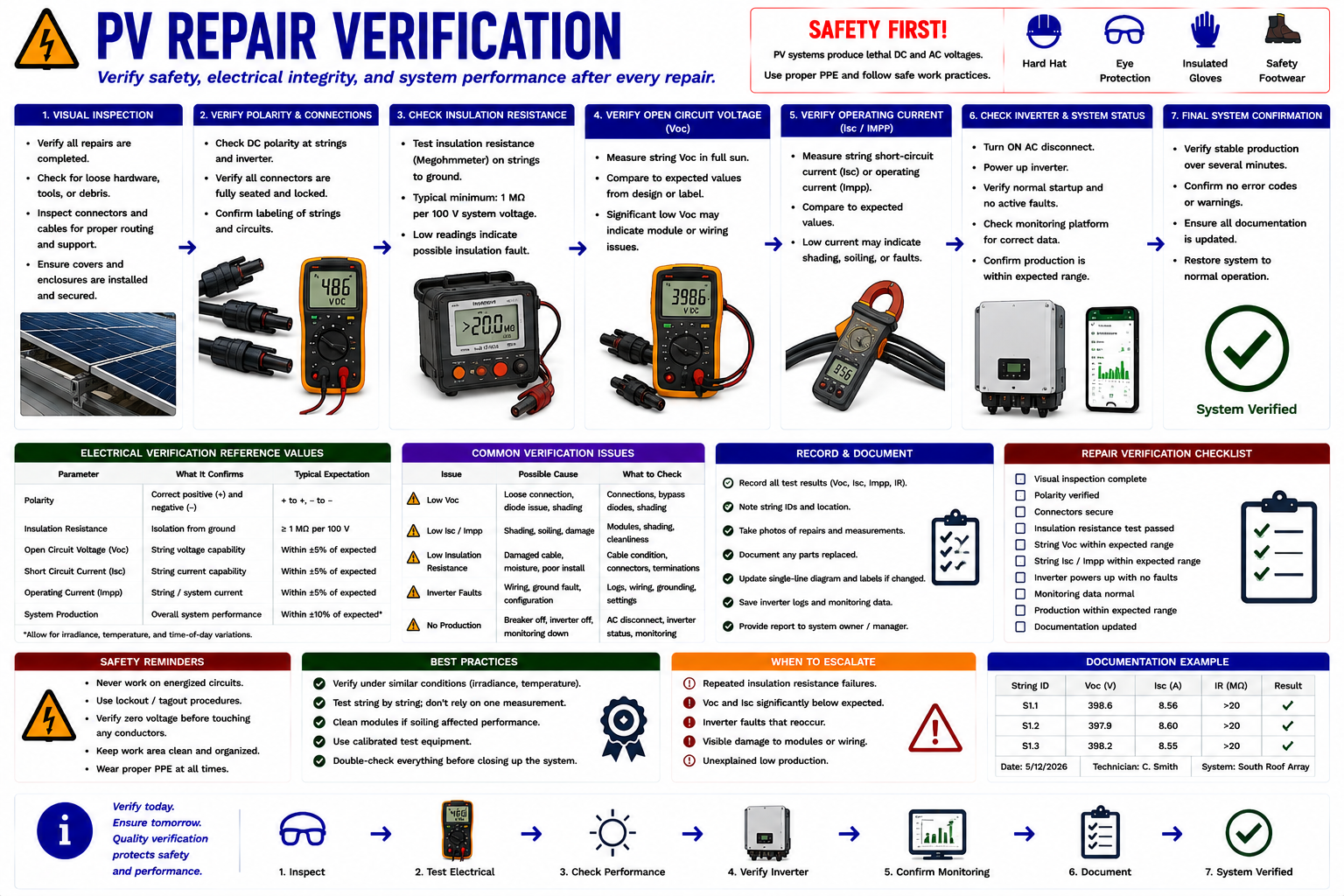
Confirm the Component, Circuit, and Complete System
Inspect the Completed Repair
Check workmanship, mounting, conductor support, connector engagement, labels, enclosures, and affected mechanical components.
Verify Electrical Conditions
Repeat the voltage, current, continuity, insulation, or other measurement relevant to the original diagnosis.
Verify Inverter Operation
Confirm normal startup, operating status, AC output, DC input, and absence of relevant active faults.
Verify Monitoring
Confirm that repaired or replaced module-level equipment appears correctly in the monitoring system when applicable.
Compare Similar Circuits
Verify that the repaired string, module, or branch now behaves reasonably compared with similar equipment under the same conditions.
Confirm the Original Complaint
Determine whether the issue that initiated the service call has actually been resolved.
An Inverter Returning Online Is Only One Verification Point
A system can restart while one string remains disconnected, one module remains offline, monitoring remains incorrect, or a repaired connection continues to overheat.
Verify the particular circuit and condition that was repaired rather than using inverter startup alone as proof of successful service.
Create a Service Record Another Technician Can Use
The final service record should allow someone who was not present at the repair to understand the original complaint, what was found, what measurements established the diagnosis, what work was performed, and how successful operation was verified.
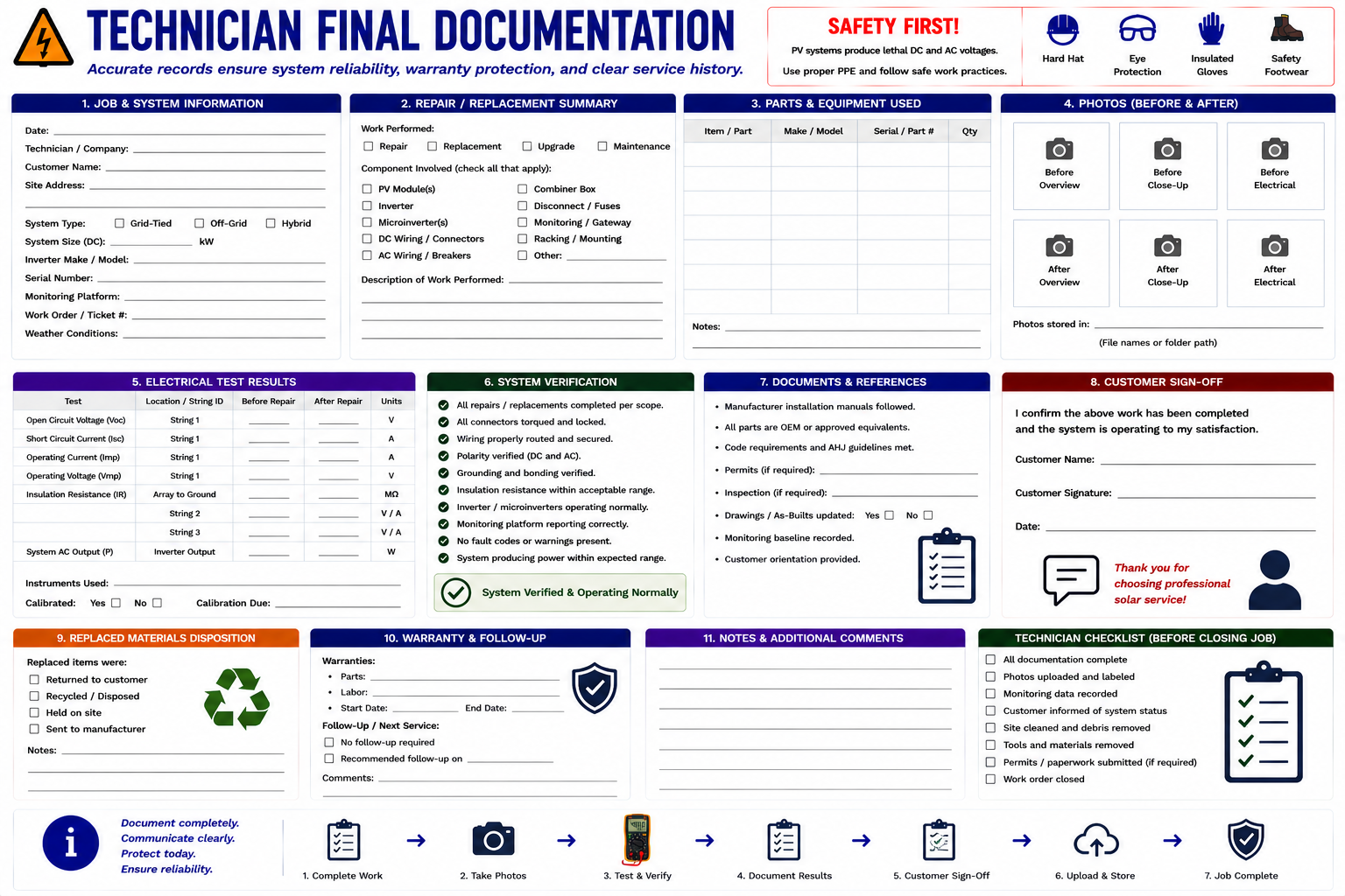
Record the Complete Service Process
Original Complaint
Record the condition reported by the customer, operator, or monitoring system.
System Information
Identify relevant module, inverter, optimizer, microinverter, combiner, battery, and electrical equipment.
Fault Information
Record inverter faults, monitoring alerts, visual findings, thermal findings, and other diagnostic evidence.
Electrical Measurements
Record relevant AC voltage, AC current, DC voltage, string current, module readings, or other measurements.
Corrective Work
Describe repairs performed, conductors or connectors replaced, equipment replaced, configuration changes, and other corrective action.
Replacement Equipment
Record manufacturer, model, serial number, ratings, and other identifying information for significant replacement components.
Verification Results
Record post-repair measurements and operating conditions demonstrating that the fault was corrected.
Final System Status
Record whether the system was restored to normal operation or whether additional work remains necessary.
Use Before-and-After Images
Photographs should show the original defect and the completed repair whenever practical. Wider photographs establish location, while close-up photographs document the specific condition.
For replacements, photograph nameplates and serial numbers when useful. This can simplify future warranty, service, and compatibility investigations.
Not Every Service Call Ends With Complete Restoration
If additional equipment, engineering review, manufacturer assistance, roof repair, electrical work, utility involvement, or another service visit is required, document the remaining condition clearly.
Record what has been isolated or left out of service and what must occur before the system can be fully restored.
Explain What Was Found and What Was Done
A concise service explanation should identify the original fault, corrective work, current system status, and any remaining recommendations without overwhelming the customer with unnecessary technical detail.
When equipment has been replaced, explain any changes in monitoring, operating behavior, warranty registration, or expected appearance that the owner may notice.
Close the Job Methodically
Confirm the Diagnosis
Make sure the corrective work addresses the fault established during troubleshooting.
Repair or Replace
Use the appropriate service method for the type of component and extent of damage.
Correct the Root Cause
Address conductor support, connector assembly, environmental exposure, airflow, mounting, or other conditions that contributed to the failure.
Inspect the Work
Check all components affected by the repair before restoration.
Restore the System
Follow the required startup sequence and confirm normal equipment status.
Repeat the Diagnostic Tests
Verify that the abnormal condition identified before repair has been corrected.
Verify Complete Operation
Check inverter output, relevant strings or module-level equipment, monitoring, and final system production.
Document Everything
Record the problem, diagnosis, measurements, repair, replacement information, verification results, and final system status.
Corrective Work Requires Control of Multiple Energy Sources
PV repair may involve utility AC, illuminated array DC, stored battery energy, capacitors within equipment, and other electrical sources. A component being replaced may remain connected to an energized source from a direction that is not obvious from its normal operating function.
Repair and replacement should be performed only by qualified personnel using the required shutdown, isolation, verification, PPE, test equipment, connector tooling, torque procedures, manufacturer instructions, and electrical safe-work practices for the installed system.
What You Should Take From This Lesson
Decide Whether the Fault Is Repairable
Localized wiring, connector, and termination problems may often be repaired, while internally failed power electronics and severely damaged modules generally require replacement.
Repair the Cause, Not Only the Damage
Determine why wiring, connectors, or equipment failed so the replacement is not exposed to the same condition.
Match Replacement Equipment Carefully
Verify electrical ratings, system compatibility, communications, physical dimensions, mounting, connectors, and other requirements before ordering replacement equipment.
Older Modules Can Be Difficult to Replace
Compare electrical characteristics and physical dimensions rather than choosing a replacement based only on wattage.
Verify the Repair
Repeat the measurements and observations that identified the original fault and confirm normal system operation afterward.
Document the Completed Service
Record the diagnosis, measurements, parts replaced, corrective work, verification results, and final system condition.
Repair, Replacement, and Documentation
You have now progressed from systematic PV diagnosis into field repair decisions, connector repair, inverter and microinverter replacement considerations, module matching, post-repair verification, and final service documentation.
The next part of the course introduces battery energy-storage systems and examines how storage changes PV system architecture, inspection, troubleshooting, service decisions, and restoration.
Repair, Replacement, and Documentation
Return to the Part IV landing page.