Using the trainer board that contains a service switch, another light switch, two light bulbs and having the tools of a screw driver, some wire with stake-on ends, and a wire cutter/stripper build the circuit shown in figure 17.
Directions:
1. Make sure the power to the board is turned off and the trainer board is unplugged.
2. Connect a black wire to the service switch.
3. Connect the other end of the black wire to one side of the switch.
4. Connect a second black wire from the switch to the first light bulb.
5. Connect a third black wire from the other side of the first light bulb to the second light bulb.
6. Connect a white wire from the other side of the second light bulb back to the neutral side of the service switch.
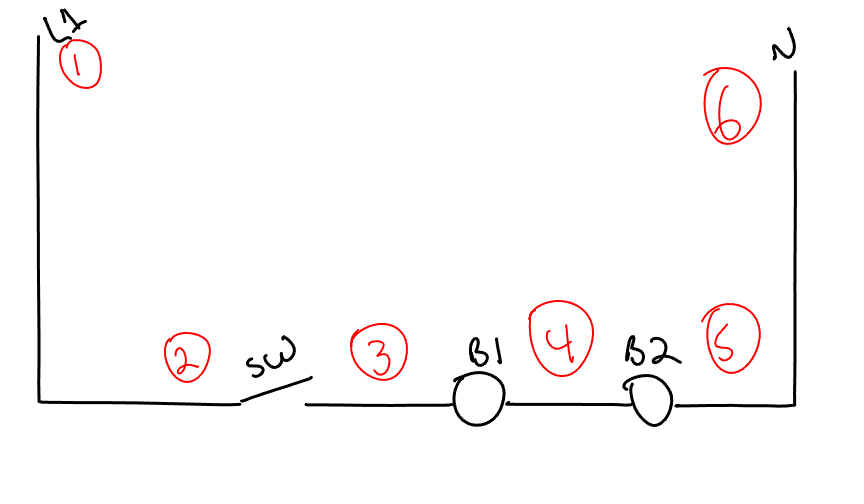
Figure 17 – A Series Circuit with one switch and two bulbs
7. If this is a school project have your instructor check to make sure wire is correct and initial this step.
8. Plug it in and turn the service switch on but leave the switch 1 off.
9. Use the steps from the prior section on meter use to check voltages at the points in the following table.
| Point 1 | Point 2 | Voltage |
| 1 | 2 | |
| 1 | 3 | |
| 1 | 4 | |
| 1 | 5 | |
| 1 | 6 | |
| 6 | 5 | |
| 6 | 4 | |
| 6 | 3 | |
| 6 | 2 | |
| 6 | 1 |
10. Now, turn switch 1 on and the bulbs should light up. If doing this project in school ask your instructor to check and initial this step.
11. Use the meter steps to check for voltages across the points in the following table.
| Point 1 | Point 2 | Voltage |
| 1 | 2 | |
| 1 | 3 | |
| 1 | 4 | |
| 1 | 5 | |
| 1 | 6 | |
| 6 | 5 | |
| 6 | 4 | |
| 6 | 3 | |
| 6 | 2 | |
| 6 | 1 |
12. Now, carefully unscrew one of the light bulbs, note what happens.
13. Use your meter to check for voltages across the points in the following table.
| Point 1 | Point 2 | Voltage |
| 1 | 2 | |
| 1 | 3 | |
| 1 | 4 | |
| 1 | 5 | |
| 1 | 6 | |
| 6 | 5 | |
| 6 | 4 | |
| 6 | 3 | |
| 6 | 2 | |
| 6 | 1 |
14. Now turn the service switch off, and unplug the board.
15. Put the meter into resistance mode, so you are measuring ohms.
16. Disconnect the two wires going to the service switch and check resistance across the points listed in the table.
| Point 1 | Point 2 | Resistance |
| 1 | 2 | |
| 1 | 3 | |
| 1 | 4 | |
| 1 | 5 | |
| 1 | 6 |
17. Turn switch 1 to the off position and once again check resistance across the points listed in the table.
| Point 1 | Point 2 | Resistance |
| 1 | 2 | |
| 1 | 3 | |
| 1 | 4 | |
| 1 | 5 | |
| 1 | 6 |
18. You should now be able to relate this shop project back to the description of a series circuit. When you are confident you can do that please call your instructor over and ask him to sign off on this project. Remember your instructor may ask you to explain what you learned.