Preparing for Electrical Testing of PV Systems
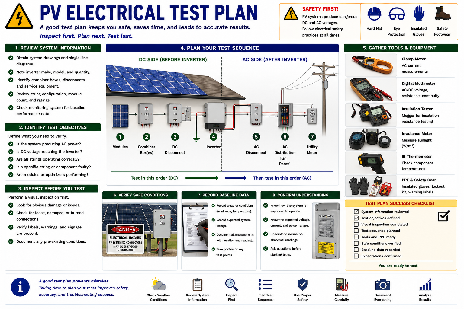
Electrical testing should begin only after the PV system has been identified and the visual inspection is complete. Before connecting a meter, the technician should understand the system architecture, identify the available energy sources, locate the intended test points, know the expected electrical values, and verify that the test equipment is suitable for the circuits being measured.
This lesson develops the electrical test plan used throughout Part III. The goal is not to collect as many readings as possible. The goal is to make each measurement answer a specific diagnostic question while working through the system in a controlled and repeatable sequence.
Plan the Test Before Connecting the Meter
A useful electrical measurement begins with a question. Is utility AC voltage present? Is the inverter producing AC current? Is DC voltage reaching the inverter? Are comparable strings operating similarly? Is a suspected module or optimizer actually different from its neighbors?
Those questions determine where to test, which instrument to use, what electrical quantity to measure, and what result should reasonably be expected.
Starting with a test plan also reduces unnecessary exposure to energized equipment and prevents the technician from moving randomly between AC and DC portions of the system.
Part III Builds on Parts I and II
Electrical troubleshooting should not begin on an unidentified system. Parts I and II established the information needed before testing: system type, inverter architecture, module and string configuration, equipment ratings, visual condition, environmental conditions, monitoring information, and visible faults.
If that information is incomplete, electrical measurements may be difficult to interpret. A voltage reading has limited diagnostic value when the technician does not know how many modules are in the string or what voltage the circuit should reasonably produce.
Technician rule: Identify first. Inspect second. Measure third. Do not use electrical testing as a substitute for understanding the system.
What Are You Trying to Prove?
Before each measurement, identify the question the test is intended to answer. This keeps the troubleshooting process focused and provides a logical reason for moving from one test point to the next.
Is Utility Power Available?
Verify the AC source and distribution conditions before assuming that a non-producing inverter has failed.
Is the Inverter Producing AC?
Voltage and current measurements on the inverter output can help determine whether useful electrical power is being delivered.
Is DC Reaching the Inverter?
On a string-inverter system, DC input measurements help determine whether the array and string circuits are supplying the inverter.
Are the Strings Comparable?
Voltage and current differences between otherwise similar strings can help localize an array-side problem.
Is the Fault Module-Level?
Individual module or optimizer testing should normally occur after broader measurements have narrowed the problem to a smaller part of the array.
Did the Repair Correct the Problem?
The same test points that identified the fault can often be used afterward to verify the repair.
Ask These Before Every Measurement
What am I measuring? Know whether the circuit is AC or DC and whether the test involves voltage, current, resistance, continuity, insulation, or another quantity.
What do I expect? Use system configuration, nameplate ratings, environmental conditions, manufacturer information, and comparable circuits to establish a reasonable range.
What will the result tell me? Know where the diagnostic process moves if the reading is normal and where it moves if the reading is abnormal.
Use an Instrument Appropriate for the Circuit
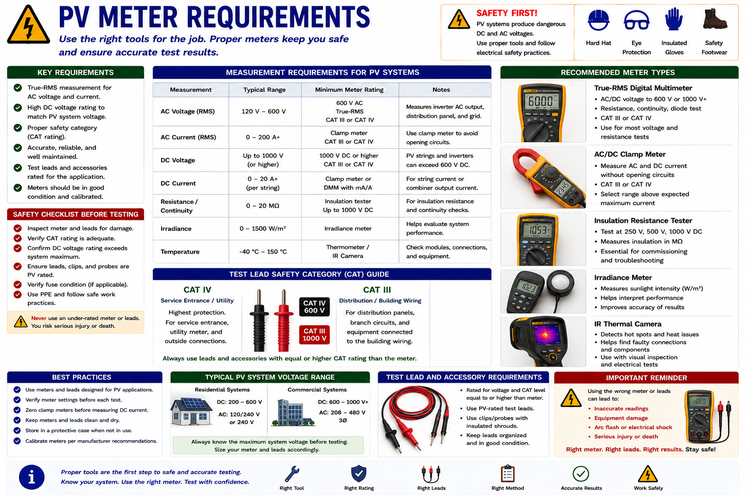
PV systems can contain both AC and DC circuits at substantial voltage. A meter suitable for ordinary residential branch-circuit work is not automatically suitable for every PV test point.
Before testing, verify the instrument’s voltage rating, measurement category, AC and DC capabilities, current range, leads, probes, clamps, accessories, and manufacturer limitations.
AC and DC Voltage Are Both Required
A digital multimeter used for PV troubleshooting should be capable of measuring both AC and DC voltage within the expected range of the installed system.
The technician should verify the meter rating before approaching the test point. This is particularly important on string-inverter systems because series-connected modules can produce substantial DC voltage.
AC Voltage
Used on utility, distribution, disconnect, inverter-output, and microinverter AC circuits.
DC Voltage
Used on string, combiner, DC disconnect, inverter-input, module, and optimizer-related circuits where appropriate.
Resistance and Continuity
Useful only under appropriate de-energized conditions and according to the test procedure being performed.
Test Leads
The leads and accessories must be appropriate for the voltage and measurement category of the circuit, not merely compatible with the meter sockets.
Know Whether the Current Is AC or DC
A clamp meter provides a useful way to measure current without intentionally opening the power circuit. The technician must still select an instrument capable of measuring the type of current present.
An AC-only clamp meter cannot correctly measure DC string current. When DC current measurement is required, use a clamp meter specifically designed and rated for DC current.
Important: Do not attempt high-current PV measurements by placing an ordinary multimeter in series unless the specific procedure and instrument are designed for that application. Clamp measurement is generally the appropriate field method for operating string or inverter current.
Zero the Instrument Before Measuring DC Current
DC-capable clamp meters commonly require the technician to zero or tare the instrument before taking a measurement. Residual magnetic fields and instrument offset can otherwise introduce error.
Follow the meter manufacturer’s procedure, close the clamp completely around one conductor, and confirm that the instrument range is appropriate for the expected current.
Use Specialized Instruments When the Question Requires Them
A digital multimeter and clamp meter perform many common field tests, but some PV diagnostic questions require specialized instruments.
Insulation Resistance Tester
Used for specific insulation and ground-fault investigations according to equipment and manufacturer procedures.
Irradiance Meter
Measures available solar irradiance and helps the technician interpret production measurements under actual field conditions.
Thermal Camera
Provides the non-contact thermal information introduced in Lesson 10 and can supplement electrical testing.
PV Analyzer or I-V Curve Tracer
Provides more detailed PV module or string performance information when required and when used according to the instrument manufacturer’s procedure.
The Meter Rating Is Only Part of the System
The electrical measurement system includes the meter, leads, probes, clips, clamps, adapters, and any other accessories between the technician and the circuit.
A highly rated meter does not make damaged or under-rated leads safe. Inspect the entire test setup before every use.
Inspect the Insulation
Look for cuts, cracking, burns, exposed conductor, contamination, or other deterioration.
Inspect Probe Tips and Shrouds
Verify that the probes and protective features are intact and suitable for the equipment being tested.
Verify Ratings
Confirm that the leads and accessories are rated appropriately for the voltage and circuit category.
Keep Equipment Clean and Dry
Contaminated or wet test equipment can create inaccurate measurements and additional electrical hazards.
Map the AC and DC Sides Before Testing
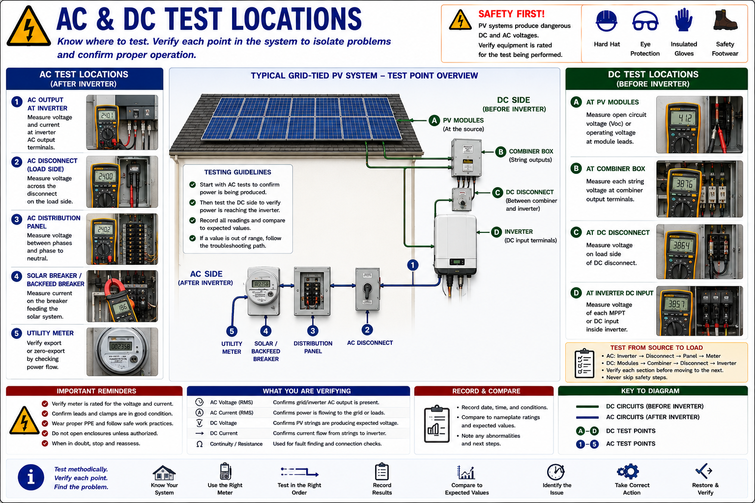
The exact test points depend on system architecture. A conventional string-inverter system contains an extended DC path between the modules and central inverter. A microinverter system performs DC-to-AC conversion at the array and therefore has a substantially different downstream test path.
Identify the architecture before opening equipment or expecting a particular voltage at a particular location.
Verify the Grid and Inverter Output
On a grid-connected system, the AC side provides useful early test locations because inverter operation depends on acceptable grid conditions and the inverter ultimately delivers its output into the AC system.
Distribution Equipment
Verify the expected utility and building AC conditions at the applicable PV connection point.
PV Breaker
Confirm circuit condition and identify the PV connection before moving toward the inverter.
AC Disconnect
When accessible and appropriate, compare the electrical condition across the PV AC disconnecting means.
Inverter AC Output
Verify whether the expected AC voltage is present and whether the inverter is delivering current under suitable operating conditions.
Microinverter Collection Equipment
On MLPE systems, AC branch circuits or combiner equipment can provide useful circuit-level test points.
Utility Connection
Grid conditions and system interconnection must be considered before diagnosing a grid-interactive inverter as failed.
Follow String Power Toward the Array
For a conventional string-inverter system, DC test points can help determine whether the PV array is delivering the expected voltage and current to the inverter.
Inverter DC Input
A useful first DC-side test location because it shows whether array power has reached the inverter.
DC Disconnect
Can help determine whether the circuit remains continuous through the disconnecting equipment.
Combiner Box
Provides string-level comparison points on systems where individual strings are brought together in accessible equipment.
Array or String
Testing closer to the array can further localize an open or abnormal string after downstream measurements identify the affected circuit.
Individual Module
Module testing occurs only after the broader diagnostic process indicates that module-level investigation is necessary.
Optimizer
Optimizer-equipped systems require the technician to distinguish the module output from the behavior of the module-level electronics.
Do Not Start by Testing Every Module
Testing individual modules can be time-consuming and may require difficult roof access. Begin at broader test locations where one measurement can evaluate a large portion of the system.
Only move toward individual strings, modules, optimizers, or microinverters after earlier evidence has narrowed the problem.
Know What Can Remain Energized
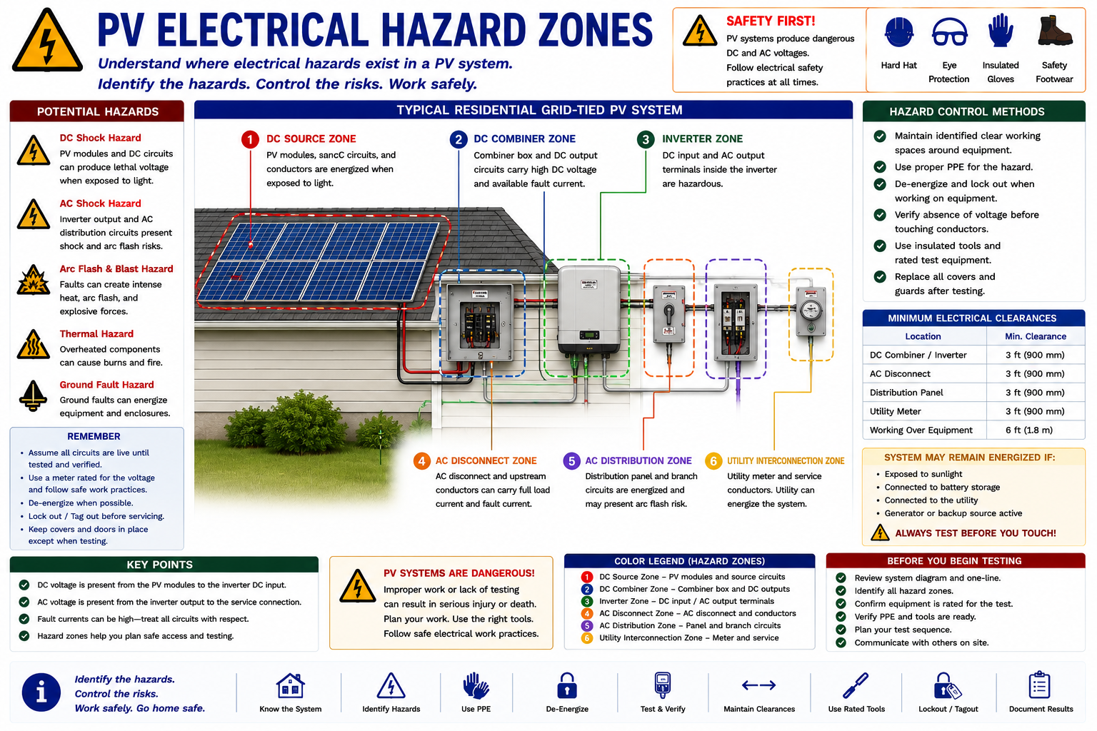
PV systems are unusual because electrical power may be available from more than one direction. Illuminated modules can energize DC circuits while the utility energizes AC circuits. Battery-equipped systems can introduce stored energy independent of both sunlight and the grid.
Operating one disconnect therefore does not automatically establish a completely de-energized system.
PV Modules Generate When Exposed to Light
Opening an AC breaker does not stop illuminated modules from generating DC voltage. Likewise, opening a downstream DC disconnect can leave source-side PV conductors energized.
The technician must identify which conductors and terminals can remain energized under the current system configuration before opening equipment or contacting conductors.
The Utility Can Energize the Other Side of the System
A grid-connected inverter operates in an electrical system that also contains utility power. AC disconnects, distribution equipment, service equipment, and inverter-output circuits may remain energized from the grid even when PV generation is absent.
Do not infer the electrical condition of one side of the inverter from the condition of the other.
Stored Energy Adds Another Source
Battery-equipped systems introduce stored DC energy and may contain hybrid inverters, transfer equipment, backup panels, gateways, and additional disconnecting means.
Part V addresses battery-system testing in detail. For Part III, the important rule is to identify battery equipment before beginning a test sequence designed for a conventional grid-tied PV system.
Know the Reasonable Range Before Testing
A meter reading is not automatically good or bad merely because it is nonzero. The technician needs a reasonable expectation derived from the installed equipment and current conditions.
Nameplate Ratings
Use inverter, module, combiner, disconnect, and other equipment ratings as appropriate.
Module Count
Series module count helps estimate reasonable DC string voltage.
System Architecture
String, microinverter, optimizer, hybrid, and battery systems create different expected test conditions.
Sunlight and Weather
Irradiance and shading strongly influence available current and power.
Temperature
Module temperature affects PV voltage and should be considered when interpreting DC readings.
Comparable Circuits
Similar strings, inverter inputs, phases, or module-level devices often provide useful real-world comparison values.
Record What the System Is Doing Before Testing Changes It
Record the operating conditions that affect the measurements. This information makes the test results useful later and prevents readings taken under different conditions from being compared incorrectly.
Date and Time
Solar position and operating conditions can change significantly during the troubleshooting visit.
Weather
Record sunlight, cloud cover, recent shading, and other environmental conditions affecting PV production.
System Status
Record inverter status, active faults, communications condition, operating mode, and available monitoring information.
Switch and Breaker Positions
Document the original operating state before intentionally changing disconnect or breaker positions.
Expected Ratings
Record the system information needed to compare measured values with reasonable expectations.
Build the Diagnosis as You Test
Electrical troubleshooting produces a chain of evidence. Record the test point, measurement, conditions, and interpretation rather than relying on memory.
Measurements that appear normal are just as important as abnormal readings because they eliminate parts of the system from further investigation.
Example: “240 VAC present” is less useful than “240 VAC measured at inverter AC output terminals at 11:15 AM; inverter status online; clear sky; output current then measured on both conductors.” Record enough information to understand what the reading proves.
Verify the Instrument Before Each Test
One of the simplest ways to create a dangerous situation or an incorrect diagnosis is to approach the circuit with the meter configured for the wrong measurement.
Select AC or DC
Confirm the electrical quantity before connecting the leads or placing the clamp around a conductor.
Select the Correct Function
Verify voltage, current, resistance, continuity, or another required function.
Verify Lead Placement
Confirm that test leads are connected to the correct meter terminals for the selected measurement.
Confirm the Rating
Verify that the meter and accessories exceed the expected voltage or current and are suitable for the circuit.
Verify Meter Operation
Follow the applicable safe-work procedure for confirming the instrument is operating properly before relying on it to establish electrical condition.
Do Not Leave the Leads Configured for Current
A multimeter lead left in a current-input terminal can create a hazardous short circuit if the technician later attempts a voltage measurement without noticing the meter configuration.
Check the function selector and lead positions before every new measurement—not only at the beginning of the service call.
Work Methodically Through the System
The following lessons develop each portion of the process in detail. The exact sequence may change with system architecture and the reported complaint, but the diagnostic logic remains consistent.
Verify the AC Side
Confirm utility conditions and determine whether PV-generated AC power is reaching the building electrical system.
Check Inverter Operation
Compare AC output, equipment status, faults, and expected operation.
Evaluate the DC Side
On string-inverter systems, determine whether expected DC voltage and current are reaching the inverter.
Compare Strings
Use comparable string measurements to localize array-side faults when necessary.
Move to Module-Level Testing
Test modules or optimizers only after the preceding evidence indicates where the problem is located.
Analyze and Verify
Combine the measurements with inspection findings, monitoring data, and equipment information to reach and later verify the diagnosis.
Assume the Circuit May Be Energized Until Its Condition Is Established
PV modules can produce hazardous DC voltage whenever sufficient light reaches them. Grid-connected portions of the installation can also be energized from the utility, and battery systems introduce stored electrical energy.
Electrical testing should be performed only by qualified personnel using the appropriate safe-work practices, PPE, equipment ratings, isolation procedures, and manufacturer instructions for the installed system. Opening one disconnect does not automatically eliminate every source of electrical energy.
What You Should Take From This Lesson
Create a Test Plan
Know the system architecture, complaint, test points, expected values, and required instruments before beginning.
Use the Correct Meter
Verify AC/DC capability, voltage and current ranges, measurement category, test leads, and accessories for the circuit being tested.
Distinguish AC From DC Current
Use a DC-capable clamp meter when measuring PV string current; an AC-only clamp meter cannot perform that measurement correctly.
Map the Test Points
Understand where the AC and DC portions of the installed system begin, end, and connect before testing them.
Understand the Hazard Zones
PV, utility, battery, and other energy sources can energize different portions of the installation independently.
Know the Expected Result
A measurement becomes useful only when it can be compared with a reasonable expected condition.
Record Every Measurement
Build a documented chain of evidence as the troubleshooting process moves from the broader system toward the fault.
Testing the AC Side of a PV System
The next lesson begins the electrical measurements. It follows the AC side from the building distribution equipment toward the inverter or microinverter collection equipment and shows how voltage and current measurements establish whether grid power is available and whether the PV system is delivering AC power.
Electrical Testing and Troubleshooting
Return to the Part III landing page for all five Electrical Testing and Troubleshooting lessons.