Inspecting PV Wiring, Connectors, Disconnects, and Equipment
Many PV system faults develop in conductors, connectors, disconnects, terminations, enclosures, and electrical equipment rather than in the modules themselves. A systematic visual inspection can often identify damaged insulation, loose or overheated connections, corrosion, water intrusion, failed protective devices, or other conditions before electrical testing begins.
This lesson follows the electrical path from the array toward the inverter and building electrical system. The technician focus is to identify visible electrical defects, preserve evidence, determine whether testing can continue safely, and decide which areas deserve closer electrical evaluation.
Follow the Electrical Path and Look for Evidence
PV wiring is exposed to sunlight, heat, wind, moisture, animals, movement, roof work, vegetation, vibration, and years of environmental exposure. Connectors and terminations may also develop resistance, corrosion, overheating, contamination, or mechanical damage.
The technician should inspect the wiring and electrical equipment before connecting test instruments. Visible evidence may identify the likely fault, reveal unsafe conditions, or change the planned troubleshooting sequence.
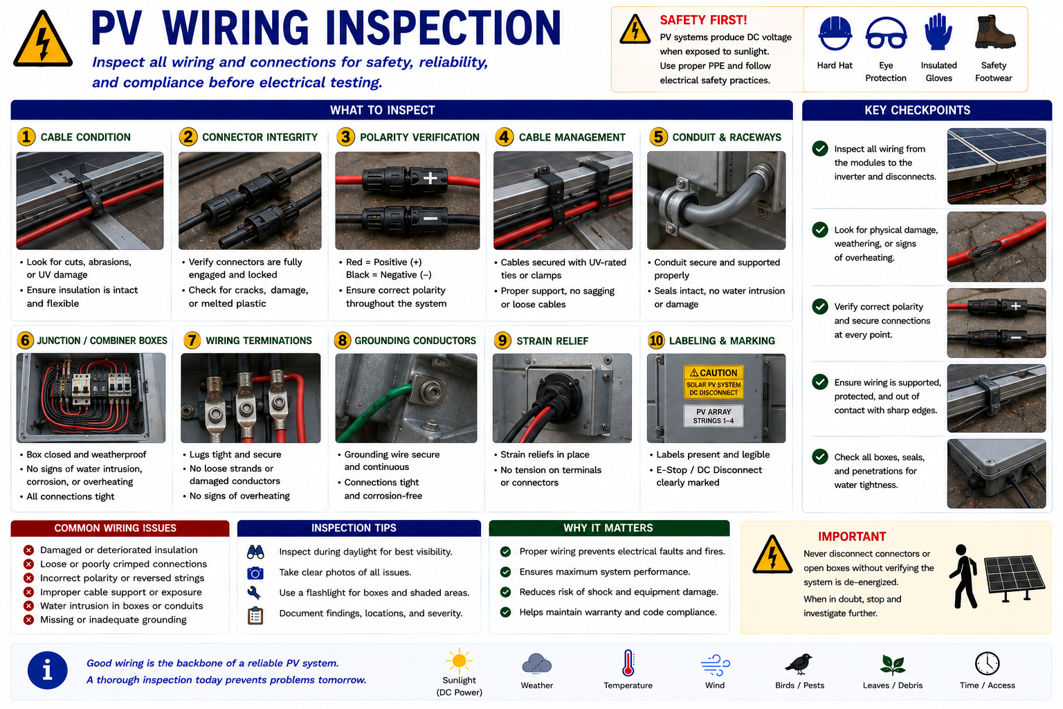
Inspect the Entire Visible Wiring Path
PV conductors may run beneath modules, across mounting systems, through raceways, along roofs, underground, or through building structures. The technician should inspect as much of the accessible path as practical without creating additional hazards.
Insulation Condition
Look for cuts, abrasion, cracking, splitting, melting, UV deterioration, punctures, or exposed conductor material.
Support
Conductors should not be hanging loose, resting on abrasive surfaces, lying in standing water, or pulled tightly against sharp edges.
Routing
Look for conductors crossing walkways, contacting roofing, touching sharp metal, being pinched by modules, or routed where movement can damage them.
Environmental Exposure
Inspect for heat, sunlight, moisture, chemicals, vegetation, animals, snow, ice, and other conditions affecting conductor life.
Physical Damage Can Become an Electrical Fault
Damaged insulation can expose conductors to moisture, grounded metal, other conductors, or accidental contact. The resulting condition may produce leakage current, ground faults, arcing, intermittent operation, or complete circuit failure.
Some conductor damage is obvious. Other problems may be hidden beneath modules, inside raceways, at cable supports, or where conductors enter equipment.
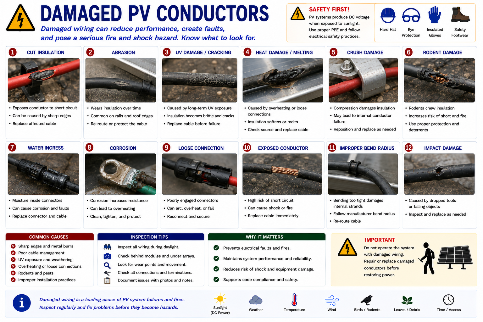
Look for the Cause, Not Only the Damage
Improper Support
Loose wiring can move in the wind, rub against roofing or metal edges, or sag into areas where water and debris collect.
Sharp Edges
Module frames, rails, brackets, conduit edges, and other metal components can damage insulation if conductors are improperly routed.
Animal Activity
Rodents and other animals may chew insulation or disturb wiring beneath arrays.
Roof Work
Roof repairs or array removal and reinstallation can pinch, cut, relocate, or improperly support PV wiring.
Heat
Electrical resistance, poor connections, environmental heat, or contact with hot surfaces can damage conductor insulation.
UV Exposure
Materials not suitable for long-term sunlight exposure can become brittle, cracked, or otherwise degraded.
An Open Circuit May Begin as a Mechanical Problem
A conductor that repeatedly moves in the wind, rubs against a rail, or is pulled tightly against a connector can eventually become an electrical fault.
When a damaged conductor is found, determine why it was damaged. Replacing or repairing the wire without correcting the routing, support, strain, or environmental cause can allow the fault to return.
Connectors Are Critical Electrical Junctions
PV connectors provide weather-resistant electrical connections between modules and related equipment. A properly assembled connector must maintain good electrical contact while protecting the connection from moisture and environmental exposure.
Connector problems can create resistance, voltage drop, heating, intermittent operation, arcing, or open circuits.
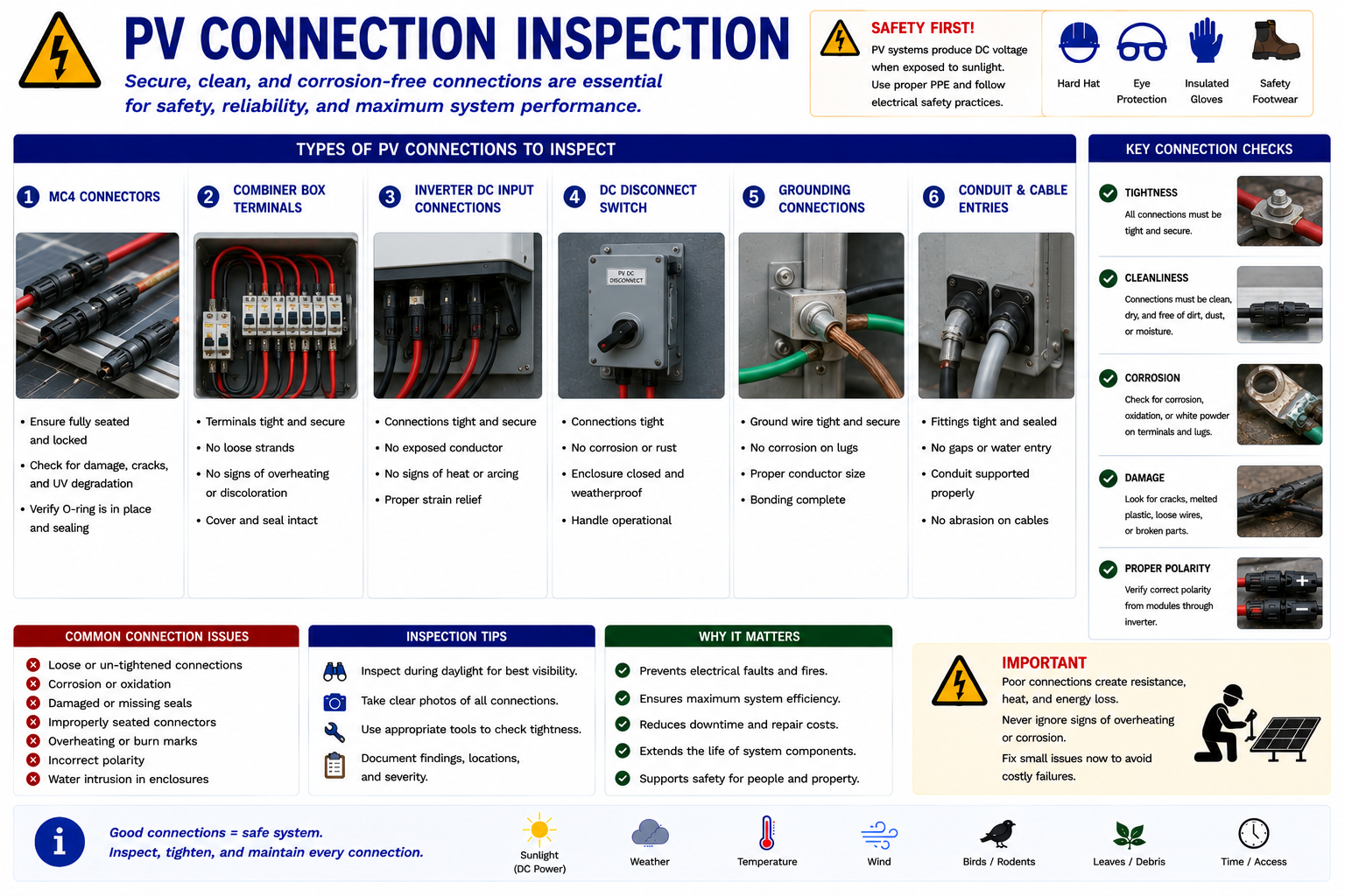
Look for Mechanical and Thermal Evidence
Check Engagement
Look for connectors that are not fully seated, have separated locking features, or show evidence that the connection has been pulled apart.
Inspect the Connector Body
Look for cracks, broken locking tabs, deformation, melting, discoloration, or other physical damage.
Look for Contamination
Moisture, dirt, corrosion, debris, or other contamination can compromise the electrical connection or sealing system.
Check Cable Strain
The conductor should not place excessive tension, twisting, or bending force on the connector.
Look for Heat Evidence
Melting, browning, darkening, deformation, or damaged nearby insulation may indicate a resistive connection or arcing event.
Similar Appearance Does Not Guarantee Compatibility
PV connectors from different manufacturers or connector families may physically resemble one another without being listed or designed for mating together.
Do not assume that two connectors are compatible simply because they can be connected mechanically. Identify the connector system and follow manufacturer requirements when repair or replacement is necessary.
Inspect the Equipment That Opens the Circuit
PV installations may contain AC disconnects, DC disconnects, inverter-integrated disconnects, battery disconnects, or other isolation equipment. The technician should identify what each disconnect controls and inspect its condition before operating or opening the enclosure.
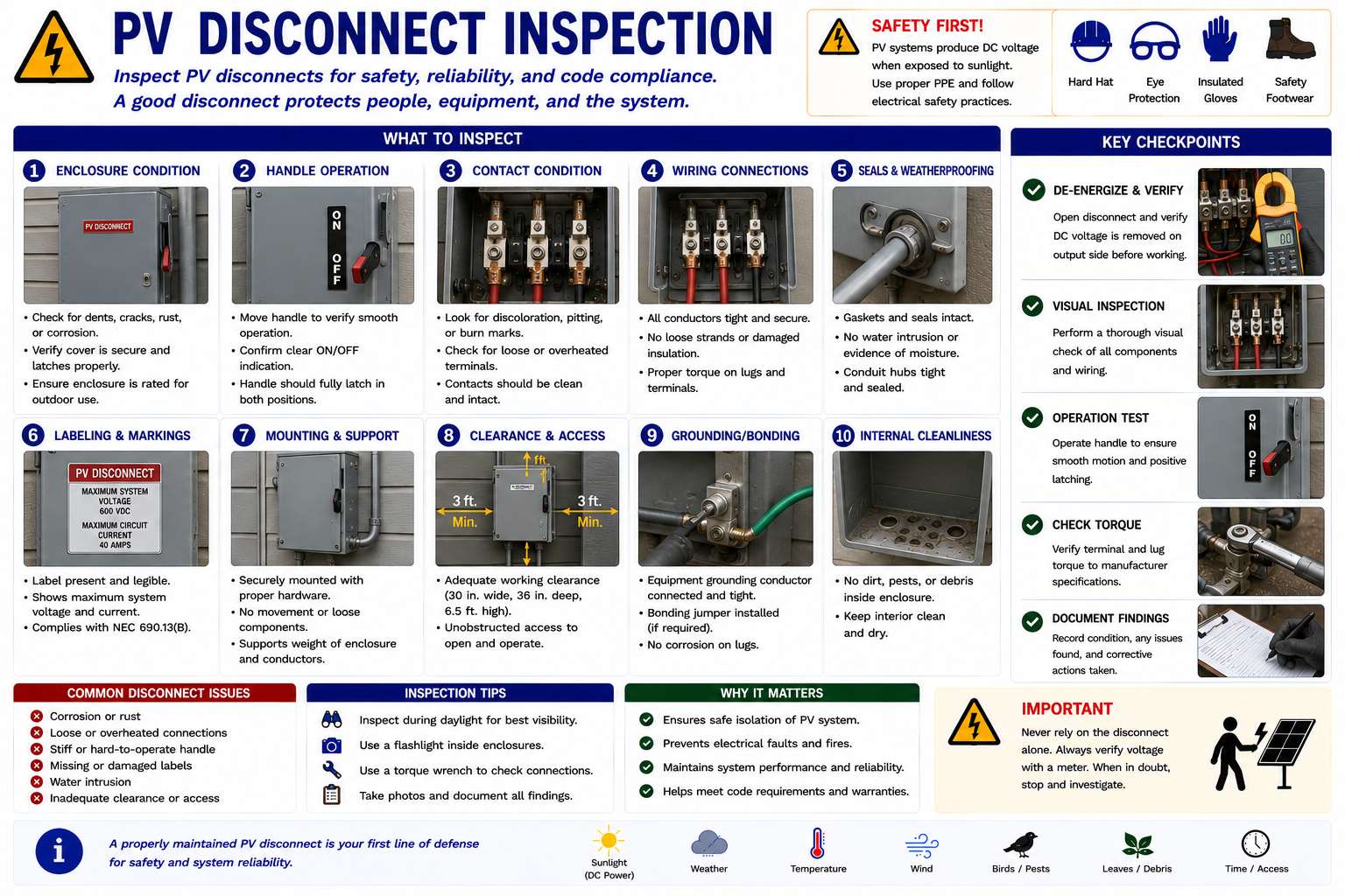
Examine the Outside Before Opening the Equipment
Enclosure
Look for cracks, impact damage, corrosion, missing hardware, open holes, failed seals, or deteriorated weather protection.
Handle and Mechanism
Check for broken, loose, damaged, or difficult-to-operate external components.
Labels
Determine what the disconnect controls and whether labels remain legible and consistent with the installed system.
Conductor Entries
Look for damaged fittings, loose raceways, open penetrations, improper strain relief, or water entry paths.
Heat Evidence
Discoloration, melted plastic, burned paint, odor, or deformation may indicate internal overheating.
Moisture
Rust, water stains, condensation, corrosion, or drainage marks can indicate compromised enclosure protection.
Opening a Disconnect Does Not Eliminate Every Energy Source
A PV array can continue producing voltage on the source side of a DC disconnect whenever sufficient light reaches the modules. Utility voltage may remain present on one side of an AC disconnect.
Battery systems can introduce additional stored-energy sources. Identify what each disconnect actually isolates before assuming the equipment is de-energized.
Read the Equipment Before Resetting It
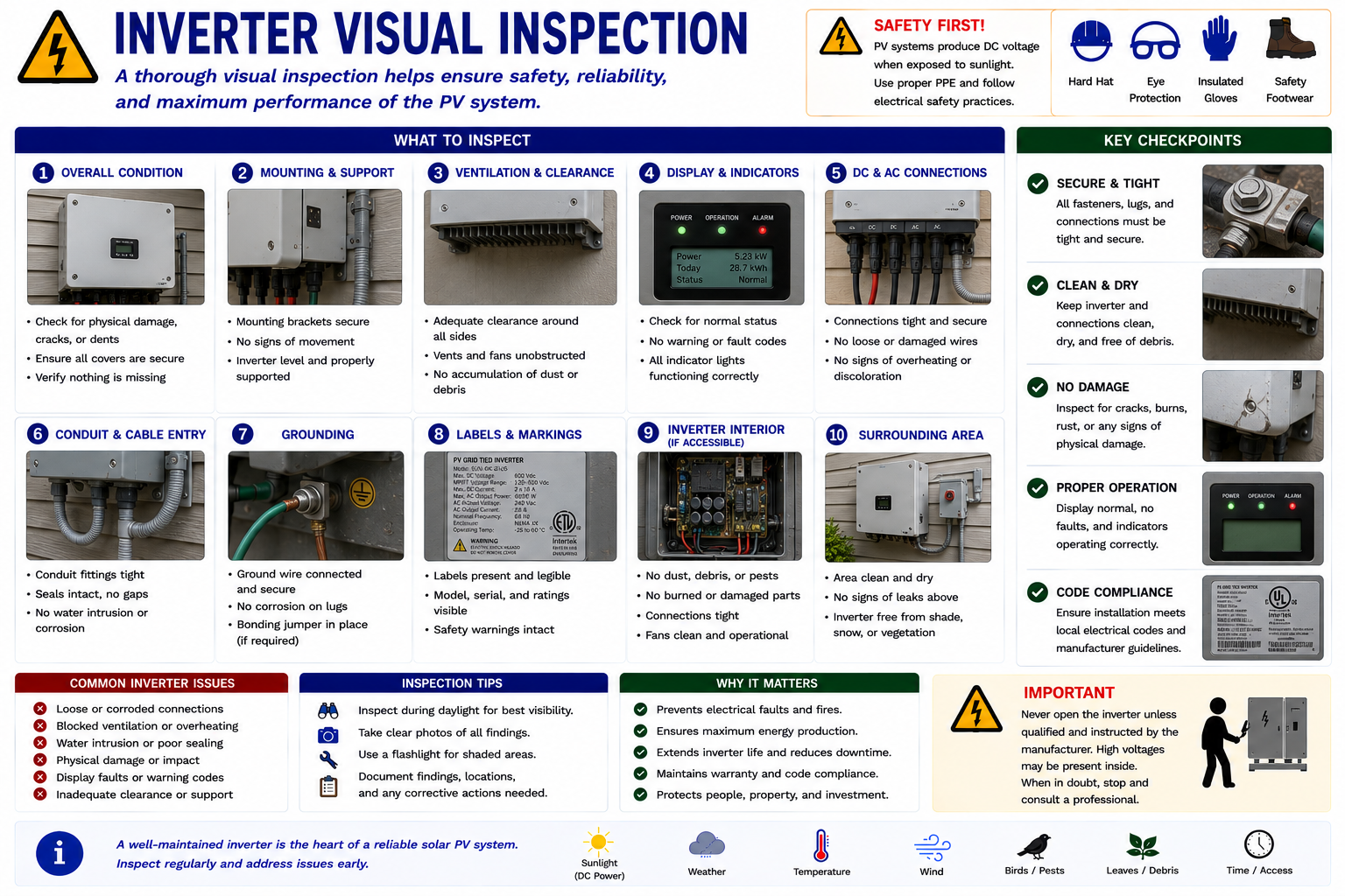
The inverter can provide important evidence through displays, status LEDs, fault indicators, event histories, audible conditions, and monitoring information. Record this information before resetting or power-cycling the equipment unless an immediate safety concern requires shutdown.
Look at the Complete Installation
Status and Fault Information
Record active faults, warnings, operating mode, displayed production, communications condition, and other available information.
Enclosure Condition
Look for corrosion, impact damage, missing fasteners, failed covers, water intrusion, or physical deterioration.
Ventilation
Check ventilation openings, fans where present, clearances, dust accumulation, vegetation, stored materials, or other conditions restricting cooling.
Conductor Entries
Inspect raceways, cable glands, fittings, seals, strain relief, and evidence of moisture entry.
Heat Evidence
Look for discoloration, burned areas, melted components, unusual odor, or other signs of abnormal temperature.
Environmental Conditions
Consider direct sunlight, high temperature, flooding, vegetation, insects, rodents, dust, salt exposure, or other site conditions affecting the inverter.
Do Not Automatically Power-Cycle the Inverter
A restart may clear an active fault or temporarily restore operation without identifying the cause. Photograph or record fault codes, status indicators, operating conditions, and monitoring information before intentionally changing equipment state.
If the system subsequently operates normally, the recorded information may be the only evidence available to diagnose the original event.
Multiple Circuits Meet in One Location
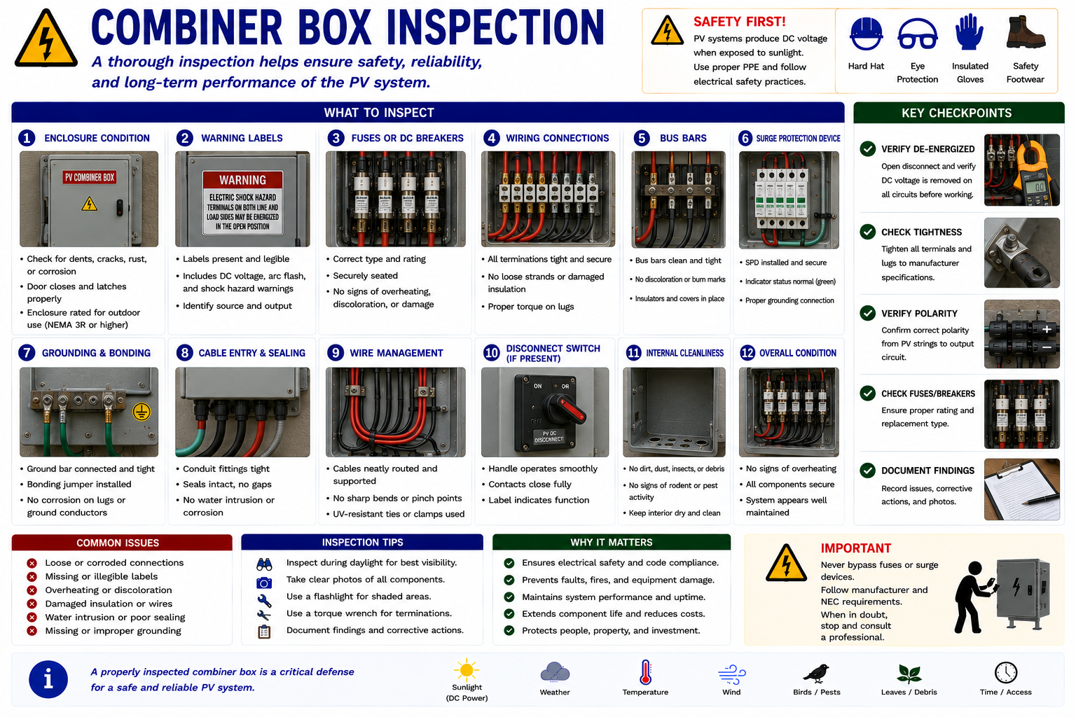
Combiner boxes and related collection equipment can contain multiple source circuits, fuses or breakers, terminals, surge devices, monitoring equipment, and a larger output circuit. Because many conductors and connection points are concentrated in one enclosure, the combiner can provide valuable visual and electrical troubleshooting information.
Look for Differences Between Similar Circuits
Identify the String Circuits
Confirm available labels and determine which array strings enter the enclosure.
Inspect Protective Devices
Look for visibly failed, overheated, damaged, corroded, or improperly installed fuses, holders, or breakers where present.
Inspect Terminations
Look for discoloration, melted insulation, corrosion, loose hardware, conductor damage, or other evidence of abnormal resistance or heating.
Inspect the Enclosure
Look for water intrusion, insects, debris, corrosion, failed seals, open penetrations, or damaged fittings.
Compare Similar Positions
A visibly different fuse holder, conductor, termination, or string input may indicate where electrical testing should be concentrated.
Water Can Create Both Immediate and Long-Term Faults
Outdoor PV equipment is designed for environmental exposure, but failed seals, damaged fittings, improperly installed raceways, condensation, flooding, or enclosure deterioration can allow moisture into electrical equipment.
Moisture can contribute to corrosion, insulation deterioration, leakage current, ground faults, tracking, and connection failures.
Look for evidence above the damage. When water is found inside an enclosure, determine where it entered rather than simply drying the equipment and returning it to service.
Discoloration Can Indicate Resistance
Electrical connections carrying current generate excessive heat when resistance becomes abnormally high. Loose terminals, damaged contacts, poor crimps, corrosion, incompatible connectors, or other connection problems can create localized overheating.
Visible evidence may include discoloration, melted insulation, warped plastics, burned surfaces, damaged connector bodies, or heat-related odor.
Thermal imaging, covered in Lesson 10, can help identify abnormal temperature differences that are not yet visible to the eye.
Inspect the Visible Fault-Current Path
Inspect accessible grounding and bonding conductors, lugs, jumpers, module-frame bonding equipment, rails, enclosures, and other visible components associated with the grounding and bonding system.
Look for loose, missing, corroded, damaged, painted-over, disconnected, or obviously disturbed components.
Do not assume a connection is electrically effective solely because it appears physically present. Electrical verification may be required when the visual inspection identifies a questionable condition.
Verify That Circuit Identification Still Makes Sense
Labels help the technician understand what equipment is connected, where alternate energy sources are present, which disconnects control which circuits, and what hazards may remain during shutdown.
Look for missing, faded, damaged, incorrect, or obsolete labels. Previous equipment changes may have left labeling that no longer matches the actual installation.
Follow the Wiring Instead of Jumping Between Components
Begin at a known point and follow the electrical path. Check each conductor route, connection, enclosure, disconnect, and piece of equipment in sequence.
This reduces the chance of overlooking a problem and creates a logical map for the electrical testing performed later in Part III.
Photograph Electrical Defects Before Repair
Visual evidence is useful for diagnosis, repair planning, warranty support, customer communication, and final documentation. Record the original condition before disturbing the fault whenever safety permits.
Wide View
Show where the damaged equipment or conductor is located within the system.
Close-Up
Photograph conductor damage, connector condition, corrosion, overheating, water intrusion, or damaged equipment in detail.
Equipment Identification
Record manufacturer, model, serial number, circuit labels, and related nameplate information.
Operating Status
Capture inverter displays, alarms, device LEDs, breaker positions, disconnect positions, and other relevant evidence.
Some Electrical Conditions Require Immediate Reassessment
The inspection should stop when the technician encounters an uncontrolled condition that makes routine inspection or testing unsafe.
Exposed Energized Conductors
Damaged insulation or open equipment may create an accessible energized condition requiring appropriate electrical safety procedures.
Active Arcing
Visible or audible arcing, active burning, smoke, or severe overheating requires an immediate safety response.
Severe Water Intrusion
Flooded or heavily contaminated electrical equipment may require isolation and specialized evaluation before further work.
Severely Damaged Equipment
Burned disconnects, melted connectors, damaged enclosures, unstable equipment, or other major faults may require shutdown or escalation.
Visual Damage Does Not Prove a Circuit Is De-Energized
A broken connector, damaged conductor, failed disconnect, or burned component may still have hazardous voltage present. PV modules can continue producing DC electrical energy whenever sufficient light reaches them, while utility-connected equipment can remain energized from the AC side.
Do not touch damaged electrical components solely because they appear failed. Identify all energy sources, follow manufacturer shutdown procedures and applicable safe-work requirements, use appropriate PPE, and verify electrical conditions with properly rated test equipment before contact.
What You Should Take From This Lesson
Follow the Electrical Path
Inspect accessible wiring and equipment systematically rather than jumping randomly between components.
Look for Conductor Damage
Abrasion, UV deterioration, animals, sharp edges, poor support, movement, and roof work can turn mechanical damage into electrical faults.
Inspect Connectors Carefully
Incomplete engagement, contamination, corrosion, strain, incompatible components, and poor electrical contact can lead to resistance and overheating.
Inspect Disconnects and Enclosures
Look for corrosion, water intrusion, labeling problems, damaged conductor entries, overheating, and physical deterioration.
Preserve Inverter Fault Information
Record displays, alarms, status indicators, and monitoring information before intentionally resetting equipment.
Use Visible Findings to Guide Testing
Visual inspection should narrow the areas requiring electrical measurements rather than merely create a list of observations.
Thermal Imaging of PV Systems
The next lesson introduces thermal imaging as another inspection and troubleshooting tool. It examines normal module thermal patterns, cell hotspots, connector overheating, camera viewing angle, and the need to verify thermal findings with additional evidence.
Visual Inspection and Assessment
Return to the Part II landing page for all four Visual Inspection and Assessment lessons.