Inspecting PV Modules and Mounting Systems
A PV array should be inspected physically before electrical troubleshooting begins. Cracked modules, damaged frames, loose mounting hardware, deteriorated wiring, vegetation, debris, roof problems, corrosion, or evidence of impact may explain poor performance or create conditions that make further testing unsafe.
This lesson focuses on recognizing visible module and mounting-system problems from a service-technician perspective. The goal is to distinguish normal appearance from damage, identify conditions requiring further investigation, and document defects before disturbing the array.
Physical Condition Can Point Directly Toward the Fault
A technician should not begin by assuming that low production is caused by an electrical component. Physical damage or environmental conditions may already provide a strong explanation.
The array inspection should include the module surfaces, frames, mounting hardware, rails or supports, roof or ground structure, visible conductors, vegetation, shading, drainage, debris, animal activity, and surrounding conditions.
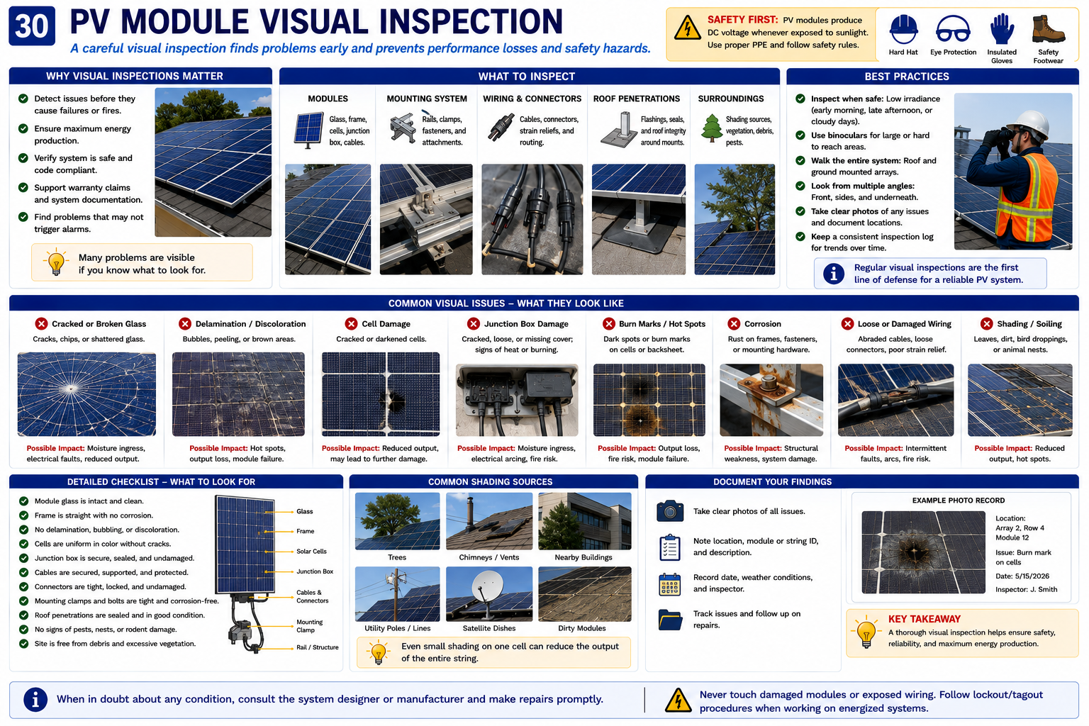
Inspect the Entire Module, Not Just the Glass
The front glass is the most visible part of a module, but it is only one area that should be inspected. Damage can involve the cells, frame, backsheet, junction box, conductors, connectors, seals, or mounting points.
Glass Surface
Look for cracks, chips, impact marks, scratches, severe contamination, burned areas, or unusual discoloration.
Cells
Look through the glass for visible broken cells, dark areas, discoloration, unusual patterns, or evidence of localized overheating.
Frame
Inspect for bending, separation, corrosion, impact damage, loose corners, or deformation affecting the mounting system.
Rear Surface
Where safely accessible, look for backsheet damage, punctures, burns, moisture evidence, delamination, or physical abrasion.
Junction Box
Look for loose attachment, cracking, heat damage, water intrusion, damaged cable entries, or other visible defects.
Output Conductors
Inspect visible leads for cuts, abrasion, UV deterioration, strain, improper support, damaged insulation, or connector problems.
Recognize the Physical Evidence
PV modules spend their service life exposed to weather, ultraviolet radiation, temperature cycling, wind, hail, snow, debris, animals, roof work, and other mechanical and environmental stresses.
Different forms of damage can produce different performance effects. Some defects are immediately obvious, while others require closer visual inspection or later thermal and electrical testing.
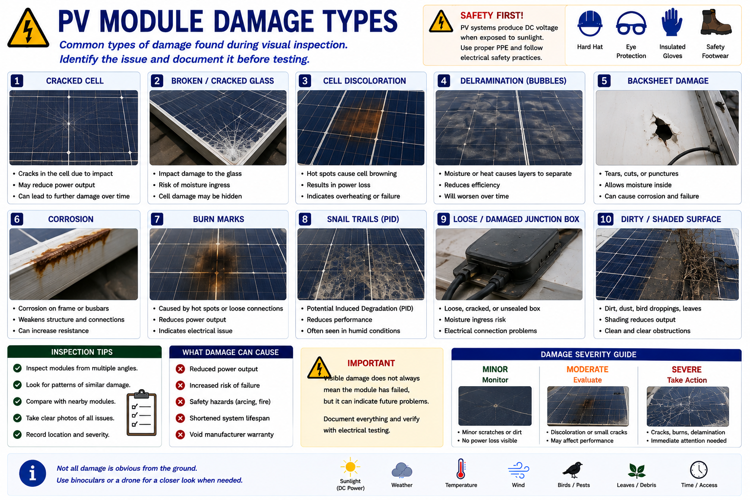
A Crack Is More Than a Cosmetic Defect
Cracked module glass can result from hail, falling objects, installation damage, thermal stress, roof work, wind-borne debris, or other physical impact.
A crack may allow moisture contamination, damage underlying cells, reduce mechanical strength, and create electrical or thermal problems. The technician should document the location and extent of the damage and avoid unnecessary handling of the module.
Field point: Do not assume that a cracked module is electrically safe simply because it is still producing power. Physical damage can change insulation and moisture protection as well as electrical performance.
Look Through the Module Surface
Visible differences within the cell area may indicate physical damage, moisture intrusion, heat-related stress, manufacturing defects, aging, or another abnormal condition.
Discoloration alone does not establish the exact electrical fault, but it provides a reason to inspect the module more closely and compare its performance with neighboring modules.
Watch for Separation Within the Module
PV modules are laminated assemblies designed to protect cells and conductors from the environment. Separation of layers, bubbles, cloudy areas, moisture patterns, or edge deterioration can indicate loss of that protection.
Moisture intrusion can lead to corrosion, insulation deterioration, leakage current, ground faults, or accelerated module degradation.
Visible Damage Is Evidence — Not Always the Complete Diagnosis
A visibly damaged module deserves investigation, but the first visible defect should not automatically be assumed to explain the entire system complaint.
Document the defect, determine what circuit it belongs to, review monitoring information when available, and confirm its electrical significance during later testing if necessary.
The Array Must Remain Mechanically Secure
The mounting system supports the modules and transfers wind, snow, and other mechanical loads to the building or ground structure. Loose, damaged, corroded, missing, or improperly installed mounting components can affect both safety and electrical reliability.
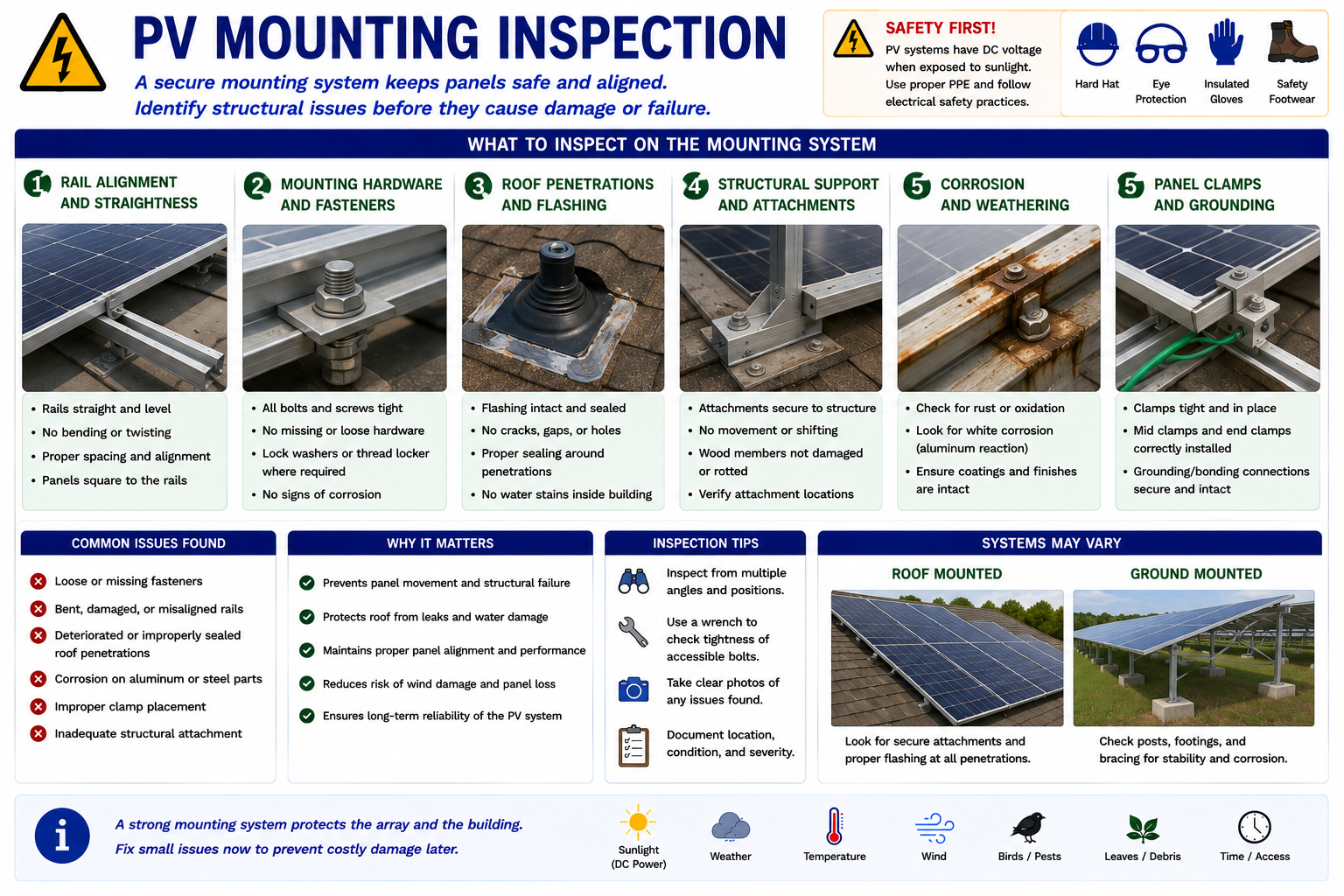
Module Clamps
Look for loose, missing, displaced, damaged, or incorrectly positioned clamps.
Rails
Inspect for bending, corrosion, loose connections, movement, damaged splices, or inadequate support.
Fasteners
Look for missing hardware, loose bolts, corrosion, damaged threads, or evidence that components have shifted.
Attachments
Inspect roof or ground attachments for movement, corrosion, cracking, deterioration, or signs that the supporting structure has changed.
Module Frames
Check for bent frames, loose corners, distortion, corrosion, or conditions affecting clamp engagement.
Bonding Components
Look for loose, missing, corroded, damaged, or obviously disturbed bonding hardware where visible.
Inspect the Array and the Roof Around It
A rooftop array creates additional inspection concerns because the PV equipment and building envelope interact. Roof deterioration, water intrusion, damaged flashing, loose attachments, drainage problems, or prior roofing work can affect the solar installation.
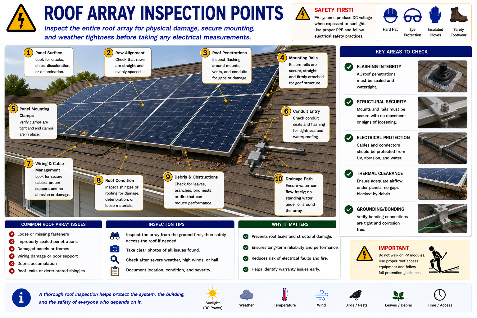
Look Around, Under, and Between the Modules
Check Roof Condition
Look for damaged roofing, missing material, deterioration, soft areas, standing water, or evidence of leaks.
Inspect Attachments and Flashing
Look for movement, missing hardware, deteriorated sealant, damaged flashing, or evidence of water intrusion near mounting points.
Inspect Beneath Accessible Modules
Look for unsupported conductors, loose connectors, debris, nesting animals, damaged wiring, failed mounting components, or module-level power electronics.
Check Drainage
Leaves, nests, cables, mounting equipment, or debris should not create unintended water accumulation or obstruct roof drainage.
Evaluate Access
Determine whether the roof can be accessed safely and whether working around the array creates fall, electrical, structural, or other hazards.
Do Not Create a Hazard to Complete the Inspection
A technician does not need to physically reach every module if doing so requires unsafe access. Steep slopes, wet roofing, snow, ice, damaged roof surfaces, excessive wind, poor ladder placement, fragile roofing, overhead conductors, or limited fall protection can make roof access inappropriate.
Use photographs, monitoring data, thermal imaging from appropriate locations, binocular inspection, drone inspection where permitted and appropriate, or other methods rather than creating an unsafe condition merely to complete a checklist.
Ground Arrays Have Different Physical Concerns
Ground-mounted PV arrays eliminate many roof-access problems but introduce other environmental and structural concerns. Soil movement, vegetation, animals, corrosion, impact damage, erosion, drainage, and exposed wiring can affect the installation.
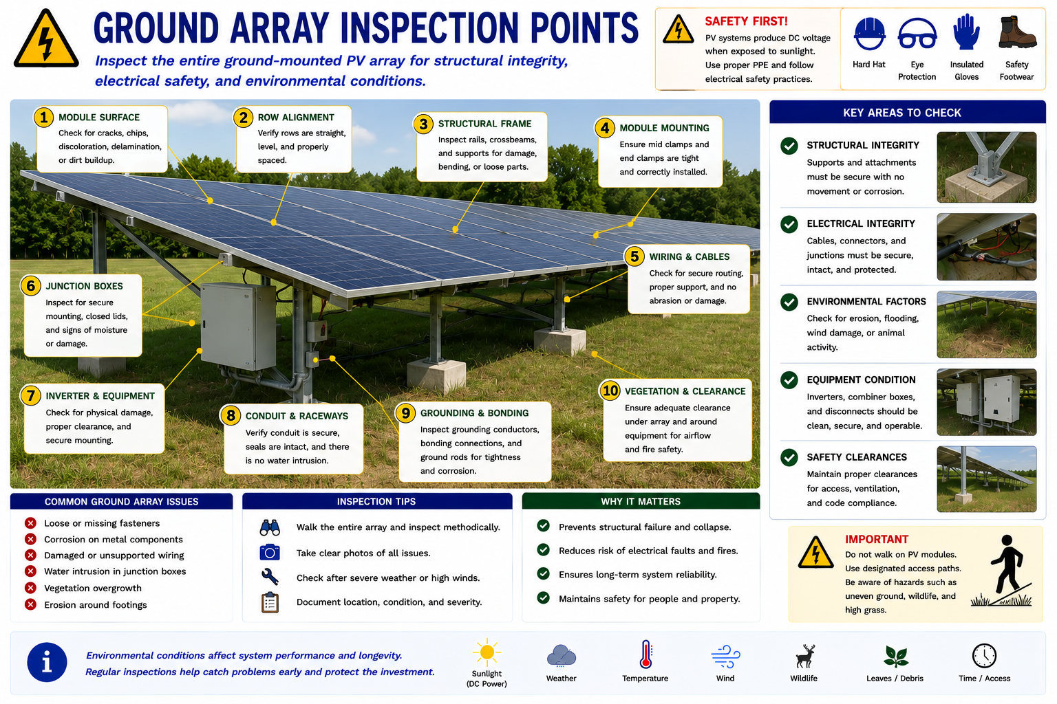
Inspect the Structure and Surroundings
Foundations
Look for movement, settlement, erosion, cracking, exposed foundations, or evidence that supports have shifted.
Support Structure
Inspect posts, rails, braces, bolts, clamps, and structural members for looseness, corrosion, impact, or deformation.
Vegetation
Look for grass, weeds, shrubs, or trees creating shade, obstructing equipment, interfering with ventilation, or contacting conductors.
Animals
Look for nests, chewing damage, burrows, droppings, insects, or other activity affecting wiring and equipment.
Drainage and Erosion
Water flow can expose cables, undermine foundations, damage raceways, or create unstable soil conditions.
Physical Impact
Ground arrays may be exposed to vehicles, landscaping equipment, falling branches, vandalism, livestock, or other impact hazards.
Look for Conditions That May Have Changed Over Time
A system that operated normally when installed may develop shading years later as trees and vegetation grow. New buildings, additions, antennas, utility equipment, signs, or other structures can also change solar exposure.
Document current shading and consider whether it corresponds with the time-of-day pattern shown in production monitoring.
Diagnostic clue: A repeated production reduction at approximately the same time each day may correspond with a predictable shadow moving across part of the array.
Not Every Production Problem Is an Electrical Failure
Dirt, dust, pollen, leaves, snow, bird deposits, industrial contamination, or other material on the module surface can reduce available sunlight.
Soiling may affect individual modules, one portion of an array, or an entire installation. Document the condition before cleaning because the pattern itself may help explain production differences.
Inspect Areas Hidden Beneath the Array
Birds, squirrels, rodents, insects, and other animals may nest beneath modules or damage exposed conductors. Material accumulated under modules can also block airflow or create moisture and fire concerns.
Look for nesting material, droppings, chewed insulation, displaced conductors, damaged connectors, or protective mesh that has failed or become detached.
Record What You Find Before Moving Anything
Photograph abnormal conditions before attempting repair, cleaning, tightening, repositioning, or component removal. Include both close-up photographs and wider photographs showing the defect’s location within the array.
Module Identification
Record which module or array location contains the defect whenever possible.
Overall View
Take a photograph showing enough surrounding equipment to establish where the problem is located.
Close-Up View
Photograph cracks, corrosion, loose hardware, damaged conductors, impact areas, moisture, or other defects in sufficient detail.
Monitoring Reference
If module-level monitoring is available, note whether the physically damaged module also shows abnormal production or device status.
Look for Patterns
One isolated defect may indicate a single component problem. Similar damage across many modules may point toward hail, installation technique, environmental exposure, manufacturing issues, roof work, or another system-wide cause.
The pattern of damage can be just as important as the individual damaged component.
Some Conditions Require the Inspection to End
The purpose of visual inspection is partly to determine whether additional work can be performed safely. Do not continue into electrical testing or equipment handling when the physical condition creates an uncontrolled hazard.
Severely Damaged Modules
Broken glass, exposed internal conductors, burned areas, severe impact damage, or other conditions may require isolation and specialized handling.
Unstable Array
Loose modules, failed supports, bent structural members, or damaged roof attachments can make work around the array unsafe.
Unsafe Roof
Structural concerns, wet surfaces, ice, damaged roofing, inadequate access, or fall hazards may prevent safe roof work.
Fire or Arcing Evidence
Burning, melted conductors, active arcing, smoke, or severe overheating requires an appropriate safety response rather than routine troubleshooting.
A Damaged Module Can Still Produce Voltage
Physical damage does not necessarily stop photovoltaic generation. A cracked, broken, or partially damaged module may continue producing substantial DC voltage whenever sufficient light reaches the cells.
Do not touch exposed conductors or damaged electrical components based only on appearance. Follow appropriate isolation procedures, manufacturer instructions, electrical safe-work requirements, PPE requirements, and verification procedures before contact.
What You Should Take From This Lesson
Inspect Before Testing
Physical damage may identify the likely fault or change the electrical troubleshooting plan.
Inspect the Complete Module
Glass, cells, frame, backsheet, junction box, conductors, connectors, and mounting points can all show useful evidence.
Inspect the Mounting System
Loose clamps, damaged rails, failed attachments, corrosion, structural movement, and bonding problems can affect both safety and reliability.
Roof and Ground Arrays Have Different Concerns
Roof systems require attention to roofing, flashing, drainage, and fall hazards, while ground arrays require attention to foundations, erosion, vegetation, animals, and physical impact.
Document Before Disturbing the Condition
Photographs and location information preserve evidence that may be important during later electrical testing or repair.
Know When to Stop
Physical damage, unstable equipment, electrical hazards, or unsafe access can make further inspection inappropriate until the hazard is controlled.
Inspecting PV Wiring, Connectors, Disconnects, and Equipment
The next lesson follows the electrical path through conductors, PV connectors, disconnects, inverter equipment, and combiner boxes. The emphasis is identifying visible electrical defects before connecting test instruments.
Visual Inspection and Assessment
Return to the Part II landing page for all four Visual Inspection and Assessment lessons.