- A schematic diagram is a map of an electrical circuit.
- A schematic diagram is broken down into paths and components.
- A schematic diagram must have a source, switch, load, and path just like a circuit.
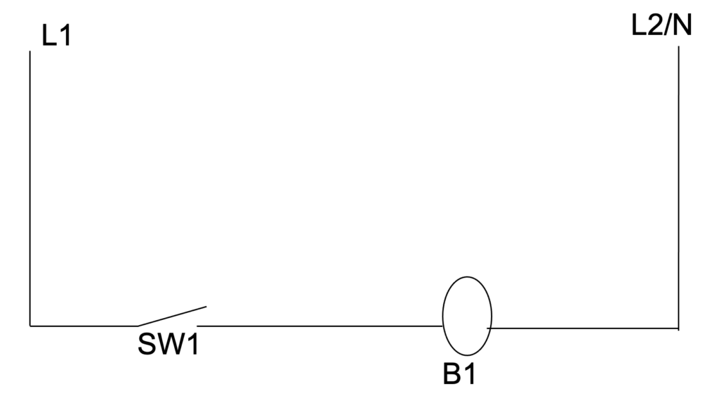
- A basic schematic is shown above. The schematic is shown in the OPEN position, this is the default, non-powered position.
- A sequence of operation is what occurs when the schematic is powered.
- In the example above the sequence of operation is:
- Switch 1 is closed
- Allows source to move to B1
- B1 is now energized.
- Switch 1 is opened.
- Interrupts current to B1
- B1 is now de-energized.
- In the example above the sequence of operation is:
- The schematic allows the technician to understand their meter readings.
- Every point of the schematic has two references:
- Load side – the side facing the load.
- Source or Line side – the side of the component facing the source or line voltage.
- Example in the above:
- The line side of SW1 is connected to L1.
- The load side of SW1 is connected to the line side of B1.
- The line side of B1 is connected to L2.
- (or this could read the neutral side of B1 is connected to neutral).
- Example in the above:
- By using a meter and holding one lead on L1 you can move the other side through the circuit, in order to each line and load side to check for differences of potential. Where there is an unexpected difference of potential a problem exists.
- Using the above circuit:
- Hold one meter lead on L1 and other lead on L2. You should read source voltage. If not – check breakers, call electrician and find out why.
- Continue to hold lead on L1 and other on line side of SW1. Should read 0v, if it has a voltage wire between L1 and SW1 is broken.
- Continue to hold lead on L1 and move to load side of SW1. Should read 0v if switch is closed. If switch is open, it will read source voltage. If switch is closed and you read source voltage the switch is bad.
- Continue to hold lead on L1 and move to line side of B1. If SW1 is closed, the voltage should be 0v. If the switch is good and you read voltage here, the path between SW1 and B1 is open (or broken).
- Continue to hold lead on L1 and move to other side of B1. You should read voltage. If you read voltage and B1 is not working B1 is bad. Replace or repair B1. If you do not read voltage at this point, check the wire between L2 and B1 it is broken.
- When checking a circuit with a meter, check one path at a time.
- When checking circuits with a meter make sure, you know what results you should be measuring based on the sequence of operation.