BASIC ELECTRICAL FOR THE HVAC TECHNICIAN
Build a Parallel Circuit
Shop Project — Build, measure and explain a two-load parallel circuit.
In the previous shop project you built a circuit with only
one current path. In this project you will connect two lamp
loads in parallel and use your meter to see how voltage and
current behave when the circuit has more than one path.
Safety First
This exercise was originally performed on a supervised
electrical training board.
Do not reproduce this exercise using household line
voltage as an unsupervised experiment.
Keep the circuit de-energized while wiring it.
Resistance measurements must also be made with the
circuit completely de-energized.
Current measurements require the meter to be inserted
in series with the conductor or branch being measured.
Never place an ammeter directly across the source or load.
What You Will Do
By the end of this project you should be able to:
Build a circuit containing two lamp loads in parallel.
Verify that each parallel branch has approximately
the source voltage across it.
Measure current in each individual branch.
Compare total circuit current with the sum of the
two branch currents.
Explain why one lamp can continue operating if the
other parallel branch opens.
Compare your actual measurements with what you
predicted before testing.
The Circuit You Are Building
Figure 18 shows the circuit for this project.
The service switch SS and circuit switch
SW are connected in series before the
circuit divides into two parallel lamp branches.
After SW, the circuit splits at the junction near
test point 7. One branch passes through
lamp B1 and the other passes through lamp B2. Both branches
connect to N on the other side of the circuit.
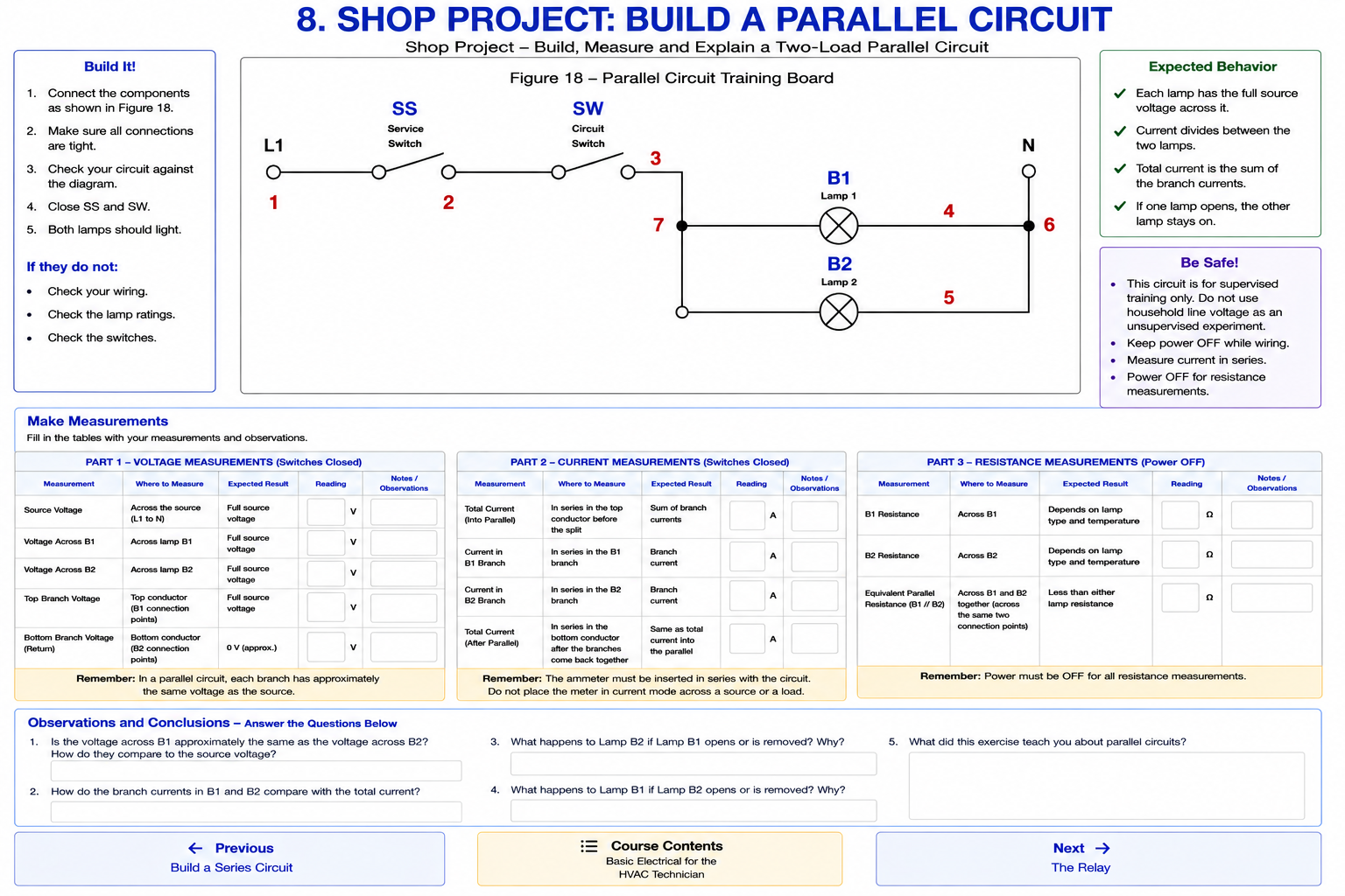
Two switches in series controlling two lamp loads
connected in parallel.
Remember the Parallel Circuit Rules
Current can flow through more than one branch.
Each parallel branch is connected across the
same source points.
Current divides between the branches according
to the branch loads.
Total current is the sum of the individual
branch currents.
Opening one lamp branch does not necessarily
interrupt the other branch.
Build the Circuit
Keep the source disconnected while making all wiring connections.
1
Connect L1 to SS
Connect L1 to the left side of the service switch
SS.
2
Connect SS to SW
Connect the right side of SS to the left side
of circuit switch SW.
3
Create the Parallel Junction
Connect the right side of SW to the junction at
test point 7.
This is where the circuit divides into two
parallel paths.
4
Connect the B1 Branch
Connect the upper parallel branch through
lamp B1 and then to N.
5
Connect the B2 Branch
Connect the lower parallel branch through
lamp B2 and then to N.
6
Inspect the Circuit
Verify that SS and SW are in series with the
source before the split, and that B1 and B2
are on separate parallel branches.
Compare your wiring carefully with Figure 18
before applying power.
Predict Before You Measure
Should the voltage across B1 be approximately the same
as the voltage across B2?
How should each lamp voltage compare with the source voltage?
Should the current through B1 necessarily be the same
as the current through B2?
What should happen to B2 if B1 opens?
What You Should Have Learned
A parallel circuit provides more than one current path.
Each parallel branch has approximately the same
voltage as the source.
Branch currents may differ depending on the loads.
Total current is the sum of the individual branch currents.
The equivalent resistance of parallel loads is less
than the resistance of either individual branch.
Opening one branch does not necessarily stop current
through the other parallel branch.
Look at the circuit before you look at the meter.
If you recognize that B1 and B2 are connected in parallel,
you should already have an idea of what the voltage across
each branch should be.
The meter is there to prove or disprove what you expect.
That habit becomes increasingly important as HVAC
control circuits become more complicated.