BASIC ELECTRICAL FOR THE HVAC TECHNICIAN
The Relay
Using a control circuit to operate contacts in another circuit.
Relays are used throughout HVAC/R equipment. A relay allows
one electrical circuit to control one or more contacts that
can operate another circuit.
Why Relays Matter
Up to this point, the switches in our circuits have been
operated directly by hand. A relay gives us another way
to open and close electrical contacts.
Instead of moving the contacts by hand, we energize an
electromagnetic coil. The magnetic field produced by
that coil changes the position of the relay contacts.
This allows a control circuit to operate another circuit
without requiring a direct electrical connection between
the relay coil and the contacts.
The Two Basic Parts of a Relay
The Coil
The relay coil is an electrical load.
When the proper voltage is applied to the coil,
current flows through the coil and creates a
magnetic field.
That magnetic field operates the relay mechanism.
The Contacts
Relay contacts act as electrically operated switches.
The contacts may be normally open, normally closed,
or arranged in combinations that allow one common
terminal to switch between two contacts.
The coil and contacts do different jobs.
The coil is the load in the control circuit.
The contacts are switches in the circuit
they control.
They are mechanically linked by the relay mechanism,
but electrically isolated from each other.
What Does “Normal” Mean?
Relay contacts are identified by their position when the
relay coil is de-energized.
Normally Open — NO
The contact is open when the relay coil is
de-energized.
Energizing the coil causes the contact to close.
Normally Closed — NC
The contact is closed when the relay coil is
de-energized.
Energizing the coil causes the contact to open.
“Normal” always describes the contact position with
the relay coil de-energized.
Relay Operation — Pictorial View
The pictorial diagram below separates the contact circuit
from the control circuit so you can see how the coil and
contacts work together.
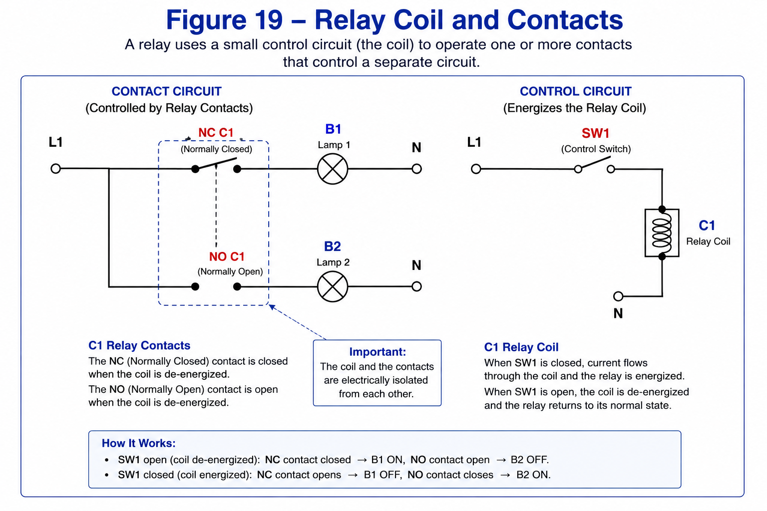
Pictorial view of relay coil C1 and the contacts
operated by that coil.
Relay Operation — Ladder Diagram
The same circuit can be represented as a ladder diagram.
This is the schematic style you will commonly use when
tracing HVAC/R control circuits.
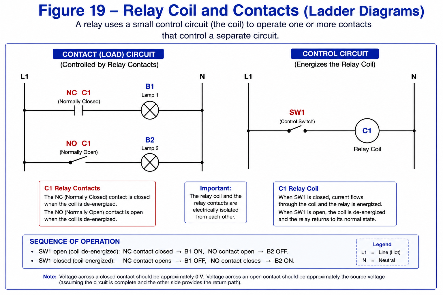
Ladder diagram of the same relay circuit.
Read the Ladder One Rung at a Time
1
B1 Rung
L1 passes through a normally closed C1
contact and then through lamp B1 to N.
With relay coil C1 de-energized, that contact is
closed, so B1 can operate.
2
B2 Rung
L1 passes through a normally open C1
contact and then through lamp B2 to N.
With relay coil C1 de-energized, that contact is
open, so B2 is off.
3
C1 Coil Rung
L1 passes through switch SW1 and then through
relay coil C1 to N.
Closing SW1 energizes the C1 coil.
4
The Contacts Change State
When C1 energizes, every contact labeled
C1 changes from its normal position.
The NC contact opens and the NO contact closes.
Relay Coil Ratings
Every relay coil is designed for a particular control voltage.
The required coil voltage is normally marked on the relay
or its nameplate.
Common HVAC/R relay coil voltages include 24 VAC, 120 VAC,
and other equipment-specific voltages.
Always match the applied voltage to the relay coil rating.
Applying excessive voltage can overheat or damage the coil.
Applying insufficient voltage may prevent the relay from
pulling in reliably or may cause the relay to chatter.
Relay Contact Ratings
Relay contacts also have electrical ratings.
Before using a relay, verify that its contacts are suitable
for the voltage, current, and type of load they will control.
Resistive Loads
Electric resistance heaters and many simple lamps
behave primarily as resistive loads.
Inductive Loads
Motors, coils, contactors, and similar devices are
inductive loads.
They can place greater switching stress on relay
contacts, especially during starting or opening.
Do not select a relay by current rating alone.
Check the manufacturer’s contact ratings for the
actual load being controlled.
Common Contact Configurations
SPST
Single Pole, Single Throw
One contact opens or closes one circuit path.
SPDT
Single Pole, Double Throw
One common contact switches between an NC and NO contact.
DPDT
Double Pole, Double Throw
Two SPDT contact sets operate from the same relay coil.
COM, NO and NC
Many relays identify their switching terminals using
these abbreviations:
Common
Normally Open
Normally Closed
On an SPDT contact set, COM is connected to NC while the
coil is de-energized. When the coil energizes, COM moves
away from NC and connects to NO.
Using Voltage to Check Relay Contacts
Measuring voltage across a relay contact can tell you
whether that contact is open or closed.
Closed Contact
Approximately 0 V
A properly closed contact has very little voltage
difference across it.
Open Contact
Approximately Source Voltage
In a complete energized circuit with a valid return
path, an open contact may have approximately the
source voltage across it.
Think before you measure.
Before putting the meter across a relay contact,
determine whether the contact should currently be
open or closed.
Sequence of Operation
A sequence of operation is a verbal or written description
of what happens in a circuit and in what order.
1. SW1 Open — C1 De-Energized
With SW1 open, no current flows through relay coil C1.
The relay contacts remain in their normal positions.
The C1 normally closed contact is closed, so B1 is energized.
The C1 normally open contact is open, so B2 is de-energized.
2. SW1 Closed — C1 Energized
Closing SW1 completes the circuit through relay coil C1.
Coil C1 energizes and changes the position of its contacts.
The C1 normally closed contact opens, de-energizing B1.
The C1 normally open contact closes, energizing B2.
Troubleshooting a Relay Circuit
When a relay-controlled load does not operate as expected,
work through the circuit in a logical order.
1
Check the Coil Rating
Verify the coil voltage printed on the relay.
2
Check Coil Voltage
When the circuit calls for the relay to energize,
check for the proper voltage across the coil.
3
Determine the Expected Contact State
Decide which contacts should be open and which
should be closed with the coil in its present state.
4
Check Across the Contacts
Use the expected voltage drop across an open or
closed contact to help determine whether the
contact is operating correctly.
Rules to Remember
The relay coil is an electrical load.
Relay contacts act as electrically operated switches.
“Normal” means the coil is de-energized.
A normally open contact is open with the coil de-energized.
A normally closed contact is closed with the coil de-energized.
Energizing the coil changes the state of its contacts.
Coil and contact ratings must match the application.
Relays allow one circuit to control another while
maintaining electrical isolation between coil and contacts.
Glossary
- Relay
-
An electrically operated switching device containing
a coil and one or more sets of contacts. - Relay Coil
-
An electromagnetic coil that operates the relay mechanism
when the proper voltage is applied. - Contact
-
The switching portion of a relay that opens or closes
an electrical circuit. - Normally Open Contact
- A contact that is open when the relay coil is de-energized.
- Normally Closed Contact
- A contact that is closed when the relay coil is de-energized.
- Common — COM
- The movable/common connection in a changeover contact set.
- Coil Voltage
- The voltage the relay coil is designed to receive.
- Sequence of Operation
-
A description of what happens in an electrical or
mechanical system and the order in which it occurs.
Follow the labels.
When you see a coil marked C1, look through the rest of
the schematic for contacts also marked C1.
Then ask one question:
Is C1 energized or de-energized right now?
Once you know that, you should be able to predict the
position of every C1 contact before taking a meter reading.