BASIC ELECTRICAL FOR THE HVAC TECHNICIAN
Line Voltage Relay Shop Project
Build, operate, measure and explain a relay-controlled
line-voltage circuit.
In the previous lesson you learned how a relay coil changes
the position of normally open and normally closed contacts.
In this project you will put that knowledge to work on the
trainer board.
Safety First
This project was designed for a supervised electrical
training board.
Do not build or modify the circuit while it is energized.
Keep the trainer unplugged while making or changing
wiring connections.
Have the completed circuit checked before power is applied.
When making resistance measurements, the circuit must
be de-energized and verified de-energized.
What You Will Do
By the end of this project you should be able to:
Identify the coil and contact terminals on the MARS relay.
Wire a relay-controlled line-voltage circuit from a ladder schematic.
Predict which relay contacts should be open or closed
with the coil energized and de-energized.
Measure voltage at selected points with SW1 open
and closed.
Relate your meter readings to the position of the
relay contacts.
Describe the complete sequence of operation in your own words.
Review the Relay Ladder Diagram
Before wiring the shop project, review the relay circuit
from the previous lesson.
Follow the circuit from L1 to N one rung at a time.
Notice that the relay coil is on its own control rung,
while the normally open and normally closed contacts
control separate load circuits.
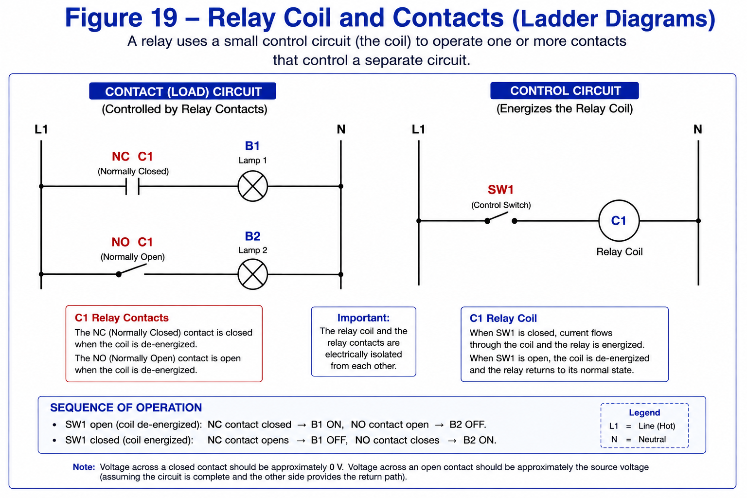
Relay coil and contacts shown as a ladder schematic.
Identify the Relay Before You Wire It
The relay used for this exercise has eight connection points:
two groups of three contact terminals and two coil terminals.
Do not assume terminal function from physical position alone.
Use the relay markings and the terminal diagram.
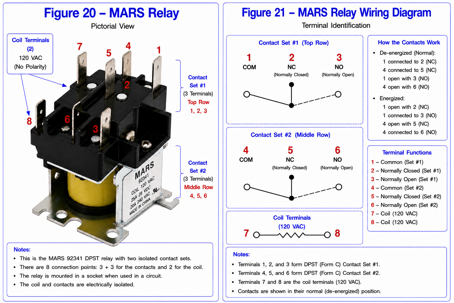
MARS relay pictorial view and terminal identification.
Relay Terminal Review
First contact set
Second contact set
120 VAC relay coil
Remember what “normal” means.
Relay contacts are identified in the position they are
in when the relay coil is de-energized.
Energizing the coil causes the normally closed contact
to open and the normally open contact to close.
The Circuit You Will Build
Figure 22 is the working diagram for this project.
Use the numbered test points when completing the measurement
tables later in the lesson.
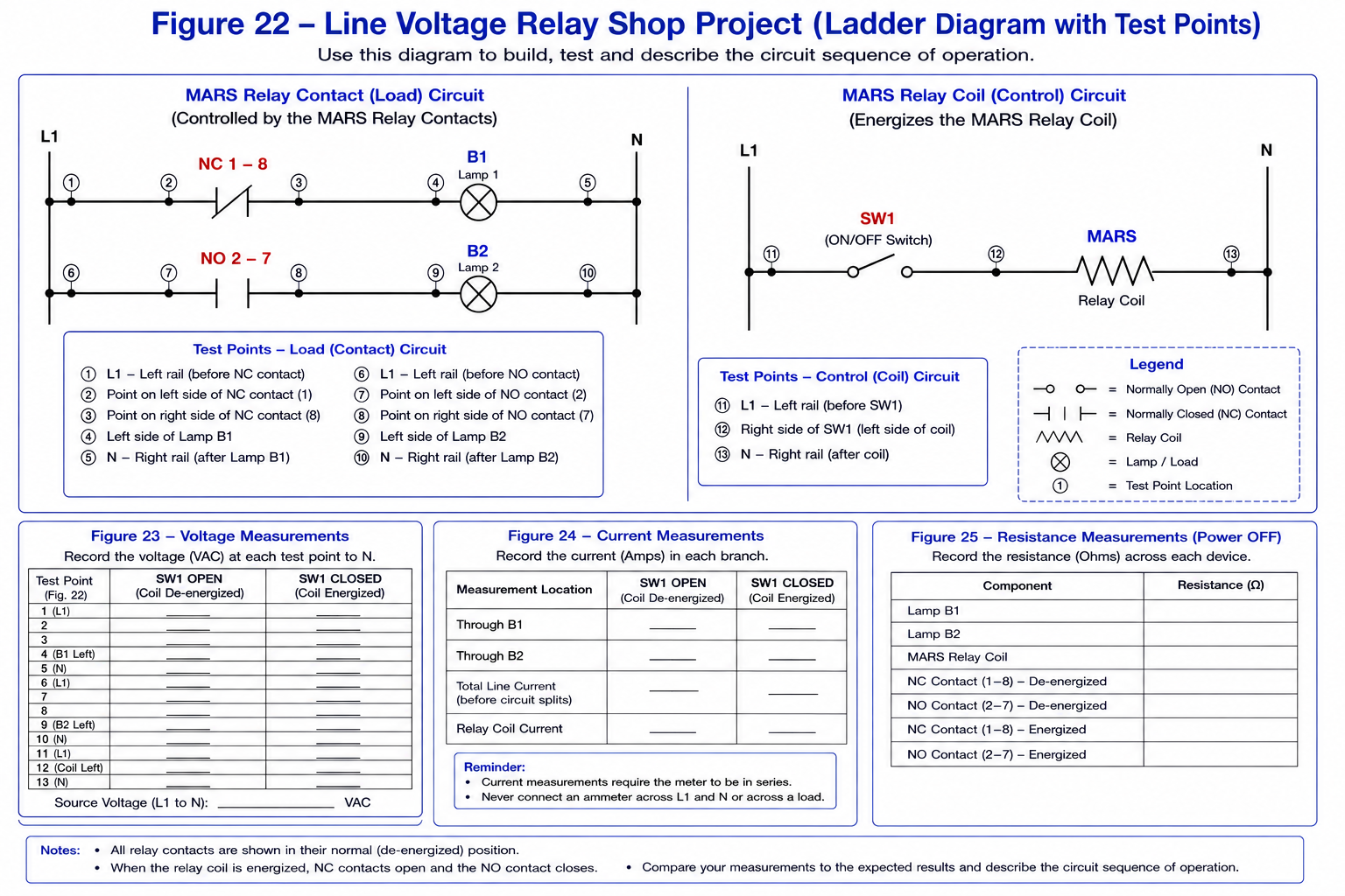
Line-voltage relay shop-project circuit with test points.
Build the Circuit
Keep the trainer unplugged while wiring.
1
Study Figure 22
Before connecting any wire, trace each rung from
L1 to N and identify the relay contact or coil
in that circuit.
2
Identify the Relay Terminals
Locate the two contact sets and the two coil
terminals on the physical relay.
Compare the relay with Figures 20 and 21 before
making connections.
3
Wire the Contact Circuits
Wire the load side of the circuit exactly as
shown in Figure 22.
Use black conductors on the line side of the loads
and white conductors from the loads back to neutral
when following the original trainer-board convention.
4
Wire the Coil Circuit
Wire SW1 and the relay coil as shown in the
control portion of Figure 22.
The 120 VAC coil used for this exercise has no
polarity requirement.
5
Inspect Every Connection
Compare each connection with the schematic.
Look specifically for unintended connections
between L1 and N.
6
Have the Circuit Checked
If this project is being completed in a classroom,
have the instructor inspect and approve the circuit
before power is applied.
Predict the sequence before applying power.
With SW1 open, is the relay coil energized or de-energized?
Which relay contact should be closed?
Which load should be energized?
When SW1 closes and the relay coil energizes, which
contact changes state and what should happen to the loads?
What You Should Have Learned
A relay coil and its contacts are electrically isolated.
Energizing the relay coil changes the state of its contacts.
Normally open and normally closed describe the contact
position with the coil de-energized.
Voltage across a properly closed contact should be
approximately zero.
Voltage across an open contact may be approximately
source voltage when the circuit provides a valid
reference path.
A ladder schematic and the sequence of operation should
let you predict meter readings before you take them.
Do not just memorize the voltage table.
Look at the schematic.
Decide whether the relay coil is energized.
Decide which contacts should be open and closed.
Then decide what voltage should exist between your two
meter leads.
If your measurement does not match what you expected,
that difference is where the troubleshooting begins.