First shop project
Now it is time to build your first shop project. It is important to follow the directions carefully and do not go faster or farther ahead than you are instructed to. Remember our safety instructions that you do not plug anything in unless your instructor tells you to.
Every student will need to wire this circuit and be able to explain the parts to the instructor. The circuit has one function as it uses the switch to turn on a light bulb.
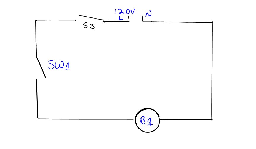
Go to one of the circuit panels. Find the switch that has the plug coming out of it this is labeled SS. That is your source or Service Switch. Next to the switch locate where there is a black and white wire connected to it. The black wire is the line voltage, represented by L1 on figure 4. The white wire is the neutral, represented by N on figure 4.
Now, locate the other switch on the board. This switch is labeled SW1. This switch has two black wires coming out of it that are connected to a circuit board.
Take a long black wire and connect the black wire from SS to one of the wires from SW1.
Now, find the light bulb marked B1 and locate a white and black wire coming from the bulb. Connect the other wire from SW1 to the black wire coming out of B1.
Finally connect the white wire from B1 to the White wire at SS (Service Switch).
You have now connected all of the required components of a circuit. You have the Source, the Path, the Switch, and the Load. The source is SS (or the plug for the wall), the path is the wire. The switch is SW1, and the load is the light bulb. Every circuit you ever create or work on will have a source, a switch, and a load.
Turn the switch on and off and make sure you can identify the Open Switch and Closed Switch positions. Does the light bulb come on when the switch is open or closed?
Have your instructor initial the spot in this manual for completing Shop 1 and then continue on to the next section. Make sure you understand the symbols, the diagram, and your wiring of the source, switch, path, and load.
Figure 4 – Shop Wiring Diagram Basic Circuit