Service Tools, Manifolds, Hoses, and Refrigerant Access
Before a technician can measure system pressure, recover refrigerant, evacuate a system, or add refrigerant, the refrigeration circuit must be accessed with tools appropriate for the refrigerant and the equipment. Manifold gauge sets, hoses, low-loss fittings, access valves, service valves, core-removal tools, and electronic instruments all provide ways to work with a sealed refrigeration system.
These tools must be used correctly because connecting service equipment temporarily opens a path between a pressurized refrigeration system and the technician’s tools. Incorrect hose connections, unsuitable pressure ratings, damaged fittings, improperly positioned service valves, or tools not approved for the refrigerant can cause refrigerant loss, contamination, inaccurate measurements, equipment damage, or personal injury.
Learning Objectives
Use a Manifold Gauge Set
Identify the low-side gauge, high-side gauge, manifold valves, service hose, and common hose connections.
Connect Hoses Correctly
Understand the common blue, red, and yellow hose functions and recognize that hose color does not replace verifying the actual connection.
Access the Refrigeration Circuit
Recognize Schrader-type access valves, service valves, valve cores, and temporary access devices.
Select Appropriate Tools
Verify pressure ratings, refrigerant compatibility, A2L suitability, and manufacturer requirements before connecting service equipment.
The Technician’s Connection to the Refrigeration System
A manifold gauge set provides a convenient way to connect pressure instruments and service equipment to a refrigeration system. Traditional analog manifolds use separate low- and high-pressure gauges, while electronic manifolds may combine pressure sensors, temperature probes, refrigerant pressure-temperature data, and calculated values such as superheat and subcooling.
Regardless of whether the manifold is analog or electronic, the technician must understand what each connection does rather than relying only on hose color or instrument automation.
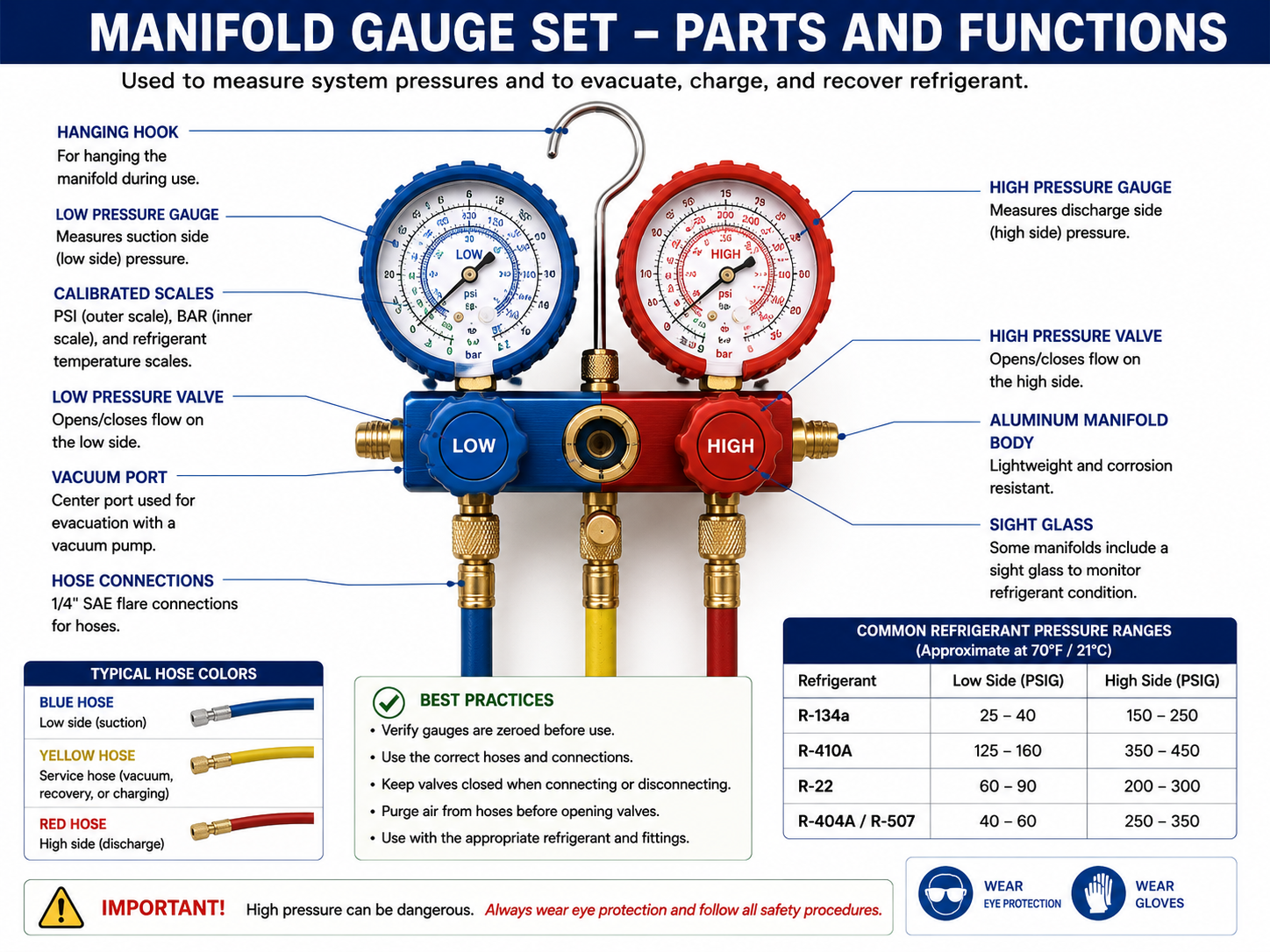
Low-Side Gauge
Measures pressure on the lower-pressure side of the system. A traditional compound gauge can also indicate pressure below atmospheric pressure during evacuation or other service conditions.
High-Side Gauge
Measures the higher pressures encountered on the discharge and liquid portions of the refrigeration circuit.
Manifold Valves
Control communication between the system connections and the center service connection. Valve position determines which paths through the manifold are open.
Center Service Connection
Connects equipment such as a refrigerant cylinder, vacuum pump, or recovery machine depending on the service procedure.
The Blue Side of a Traditional Manifold
Traditional HVAC/R practice commonly uses a blue hose for the low-side connection. The hose connects the manifold’s low-pressure side to an appropriate low-side service port.
On many comfort-cooling systems, this connection is located on the suction line. However, system designs vary. The correct service connection should be identified from the equipment design and service information rather than simply connecting to whichever fitting appears convenient.
The Red Side of a Traditional Manifold
A red hose is commonly used for the high-pressure side of a traditional manifold gauge set. It is connected to an appropriate high-side service port, often on the liquid side of comfort-cooling equipment.
High-side pressure can be substantially greater than low-side pressure. The gauge, hose, fittings, and manifold must therefore have working-pressure ratings suitable for the refrigerant and system being serviced.
Pressure Rating Matters
A manifold or hose that was appropriate for one refrigerant or equipment generation is not automatically appropriate for another. Verify the maximum working pressure of every pressure-containing service component before connecting it to the system.
The Yellow Hose Changes Function With the Job
The center connection of a traditional manifold is commonly associated with a yellow service hose. Unlike the red and blue hoses, its function changes depending on the service operation.
Charging
The center hose may connect to a refrigerant cylinder or charging device.
Evacuation
The center connection may connect to a vacuum pump, although modern evacuation practices often use larger dedicated vacuum hoses and valve-core removal tools to improve conductance.
Recovery
A recovery setup may connect the refrigeration system, recovery machine, and recovery cylinder using a configuration appropriate to the equipment and procedure.
Other Service Operations
The service connection may also be used in controlled transfer or other manufacturer-approved procedures.
Know Where Every Hose Goes Before Opening a Valve
Many serious service mistakes occur because a hose is connected incorrectly or a manifold valve is opened without understanding the resulting flow path. Before opening a manifold valve, trace the refrigerant path mentally from the system, through the hose and manifold, to the connected service equipment.
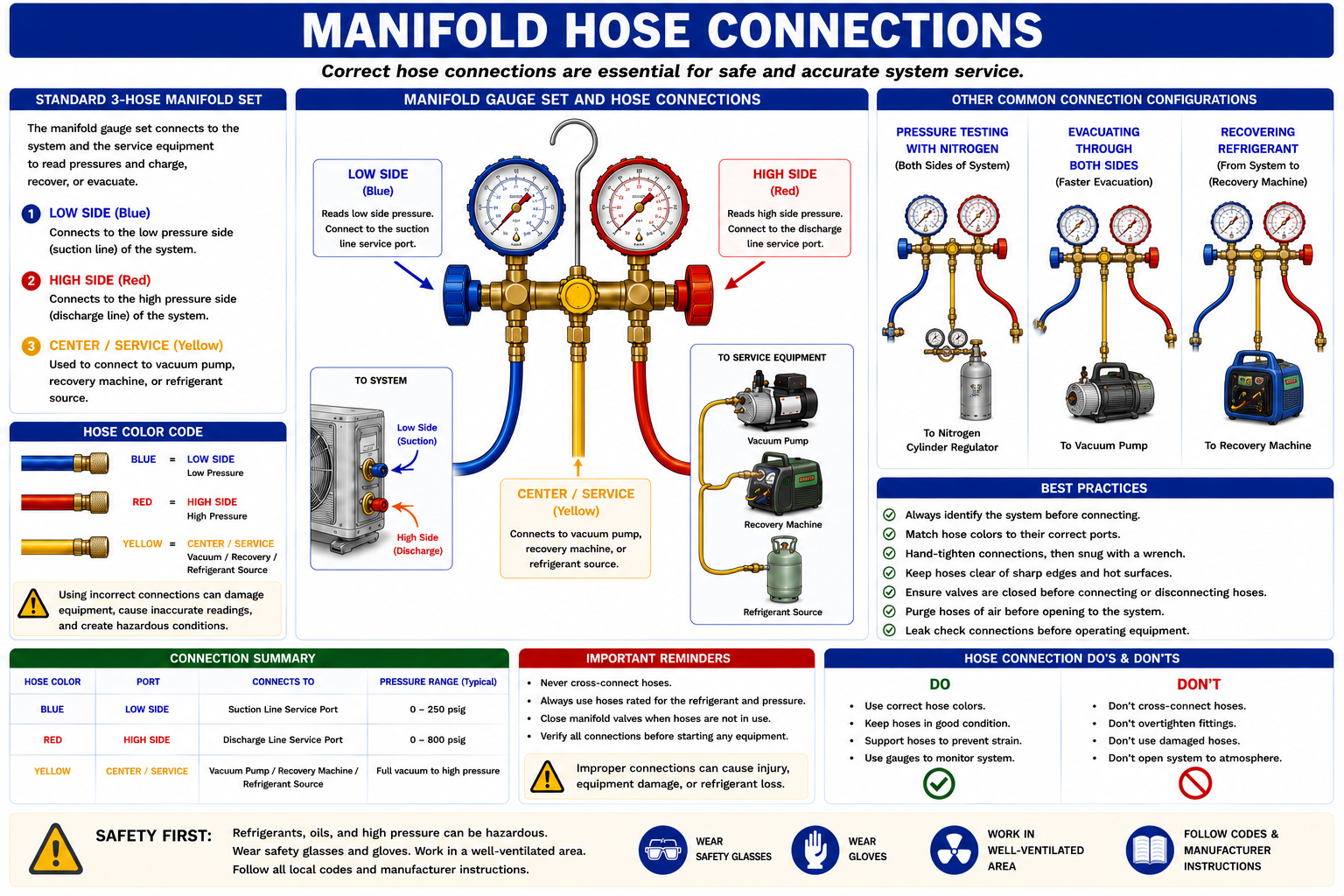
Identify the Refrigerant
Confirm the refrigerant and equipment before selecting gauges and hoses.
Identify the Ports
Determine which system connection is low side and which is high side.
Verify Tool Ratings
Confirm that the manifold, hoses, and fittings are appropriate for the refrigerant pressure and safety classification.
Verify Valve Positions
Know which manifold and system valves are open or closed before connecting or transferring refrigerant.
Service Hoses Contain Refrigerant Too
When a hose is connected to a pressurized system, the internal volume of that hose can contain refrigerant. Disconnecting a conventional fitting can therefore release refrigerant trapped between the system access valve and the manifold or hose end.
Technicians should minimize this loss through appropriate equipment and procedures. Hose length, internal diameter, fitting design, and the procedure used during connection and disconnection all influence the amount of refrigerant contained in the service equipment.
Reducing Refrigerant Released During Service
Low-loss fittings are designed to reduce refrigerant released when service hoses are connected to or disconnected from an appliance. Depending on the design, the fitting controls when the access valve core is depressed and limits the amount of refrigerant trapped at the connection.
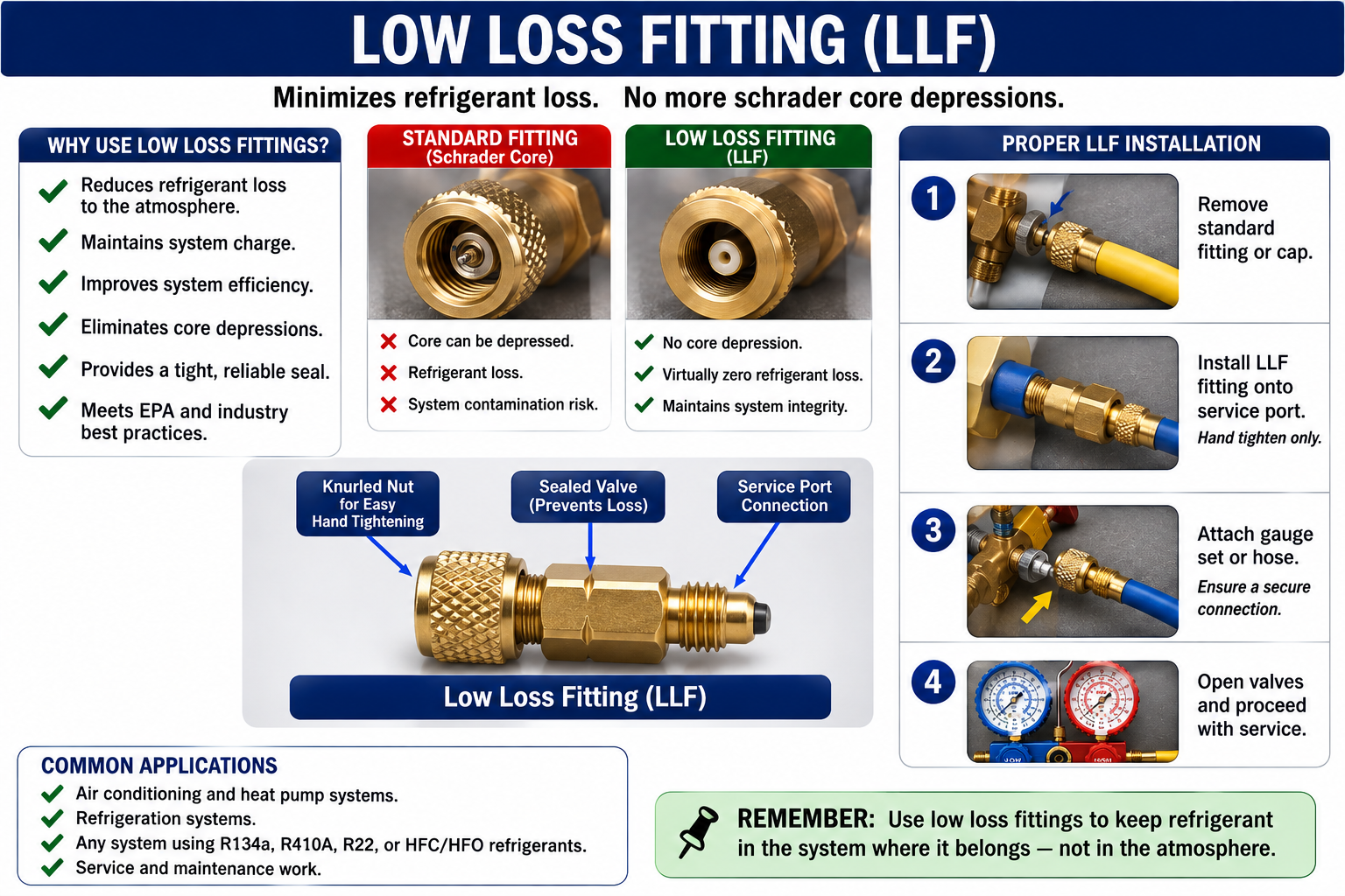
Low Loss Does Not Mean Zero Loss
Even a low-loss fitting must be used correctly. Damaged seals, worn fittings, improper connection, residual hose pressure, or incorrect procedures can still release refrigerant.
A Common Refrigerant Access Point
Many refrigeration and air-conditioning systems use a spring-loaded valve core similar in principle to a tire valve. In HVAC/R service this is commonly called a Schrader valve or Schrader-type access valve.
When no service tool is attached, the spring-loaded core seals the refrigerant inside the system. When an appropriate fitting is attached, a depressor in the fitting can open the valve core and allow pressure measurement or refrigerant flow.
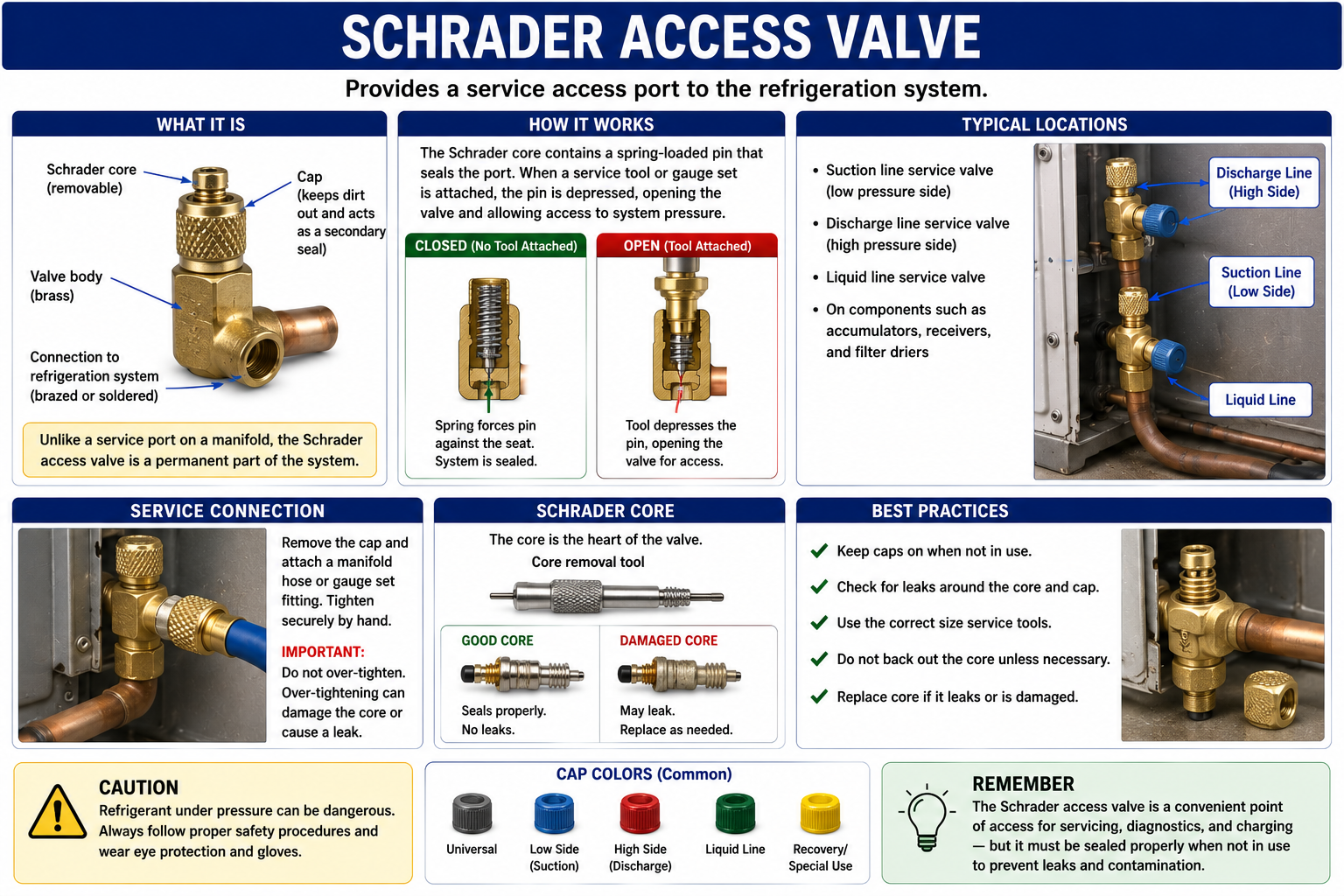
Removing Restrictions During Evacuation and Recovery
A Schrader valve core creates a restriction in the refrigerant path. During ordinary pressure measurement this restriction may be acceptable, but during evacuation or recovery it can reduce flow.
A valve-core removal tool allows a technician to remove and reinstall the core while maintaining control of the system connection. When properly used, this can greatly improve flow through the service connection, particularly during deep evacuation.
Core Removal Exposes a Large Opening
Removing a valve core from a pressurized refrigeration system without the correct tool and procedure can produce an uncontrolled refrigerant release. Use equipment specifically designed for the operation.
Valves Can Control Both Refrigerant Flow and Service Access
Some refrigeration equipment uses service valves that can be positioned to control refrigerant flow through the system and access to the service port. Traditional stem-type service valves may be described as back-seated, front-seated, or placed in an intermediate service position.
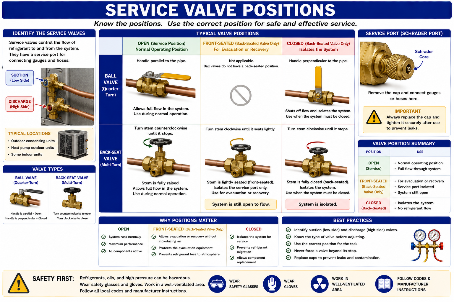
Back-Seated
On a traditional service valve, fully backing the stem out normally opens the main refrigerant passage while isolating or reducing communication with the service port, depending on valve design.
Service Position
Moving the stem away from the fully back-seated position can open communication between the system and service port while retaining the required main refrigerant flow path.
Front-Seated
Turning the stem fully inward on a traditional valve can close the main refrigerant passage and isolate a portion of the system.
Valve Designs Differ
Do not assume every service valve operates exactly like a traditional three-position valve. Modern equipment may use ball valves, rotary valves, electronic valves, dedicated service ports, or other arrangements. Follow the equipment manufacturer’s service instructions.
Solderless Access Fittings Are Not Permanent Repairs
Some service situations, particularly small sealed systems without factory service ports, may use a temporary piercing or solderless access fitting to gain access to the refrigeration circuit.
These devices can be useful for diagnosis or recovery but should not automatically be treated as permanent system components. EPA Section 608 test material has historically emphasized removing solderless access fittings at the conclusion of service when appropriate.
The Instrument Can Change — The Refrigeration Theory Does Not
Electronic manifolds can simplify field calculations by combining pressure and temperature measurements with stored refrigerant data. Many can calculate saturation temperatures, superheat, subcooling, temperature differences, and other diagnostic values.
These features are valuable, but the technician still needs to understand what the instrument is measuring and whether the correct refrigerant has been selected.
Verify Refrigerant Selection
An electronic manifold using the wrong refrigerant P-T data can produce incorrect saturation temperatures and incorrect calculated values.
Understand Bubble and Dew
When servicing a zeotropic blend, know whether the instrument is using bubble point or dew point for the calculation being performed.
Check Pressure Range
Electronic sensors have pressure limits just as analog gauges do. Do not exceed the manufacturer’s working-pressure rating.
Check Accuracy
Damaged, poorly zeroed, or improperly maintained instruments can lead to incorrect diagnosis even when the display appears precise.
New Refrigerants Can Require Different Tools
A2L refrigerants such as R-32 and R-454B introduce lower-flammability considerations that are not present with familiar A1 refrigerants such as R-410A. Technicians should therefore verify that tools and refrigerant-handling equipment are suitable for the refrigerant being serviced.
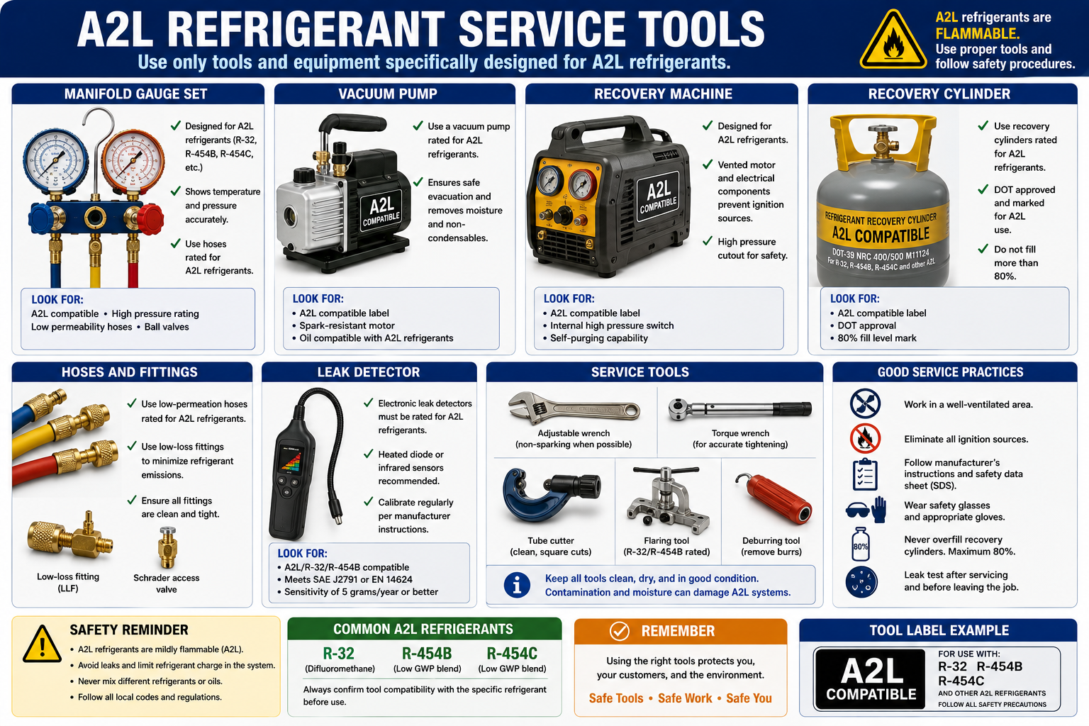
Recovery Machine
Use equipment suitable for the refrigerant and the applicable flammability classification.
Vacuum Pump
Verify manufacturer suitability for the refrigerant and service environment.
Leak Detector
Use a detector designed to detect the specific refrigerant or refrigerant family being serviced.
Manifold and Hoses
Verify refrigerant compatibility and pressure ratings rather than assuming equipment used for R-410A is automatically appropriate.
Do Not Judge A2L Compatibility by Appearance
Two recovery machines, vacuum pumps, or electronic tools can look almost identical while having different approvals or internal designs. Check the manufacturer’s specifications.
Keep Refrigerants and Service Equipment Clean
Service tools can carry refrigerant, oil, moisture, air, dirt, and other contaminants from one system to another. Hoses and manifolds that contain residual refrigerant can also contaminate another refrigerant if used without appropriate procedures.
Technicians should manage tools so that refrigerant identity and system cleanliness are maintained. Specialized work may justify dedicated hoses, manifolds, recovery machines, cylinders, or other equipment.
Prepare Before Opening the Refrigeration Circuit
Identify the Refrigerant
Read the equipment nameplate and service information.
Evaluate the Hazards
Determine the safety classification, expected pressure, and any special A2L, A3, ammonia, or CO₂ requirements.
Select the Tools
Choose gauges, hoses, fittings, detectors, recovery equipment, and other tools appropriate for the job.
Inspect the Connections
Check hoses, gaskets, O-rings, fittings, valves, and access ports for damage.
The Job Is Not Finished Until the System Is Sealed
Disconnecting service equipment is part of refrigerant management. The technician should minimize refrigerant loss from hoses and fittings, avoid introducing air into the system, and leave the equipment’s service connections properly sealed.
Manage Hose Refrigerant
Follow the appropriate procedure to minimize refrigerant remaining in or released from service hoses.
Disconnect Carefully
Use low-loss fittings or other approved connection methods and avoid exposing skin to escaping refrigerant.
Inspect the Access Port
Check for leakage from the valve core or service connection after tools are removed.
Install the Cap
Reinstall the correct service-port cap and tighten it according to the equipment manufacturer’s instructions.
Pressure Measurement Is Still Refrigerant Handling
Connecting a gauge hose may appear routine, but it places the technician directly beside a pressurized refrigerant connection. Liquid refrigerant escaping from a fitting can cause severe cold injury, and a failed hose or fitting can release refrigerant rapidly.
Eye Protection
Wear appropriate eye protection when making or breaking refrigerant connections.
Hand Protection
Use appropriate gloves when exposure to liquid refrigerant or cold fittings is possible.
Ventilation
Consider where released refrigerant could accumulate, particularly in enclosed or poorly ventilated spaces.
Inspect Before Use
Replace damaged hoses, leaking fittings, defective gauges, or other questionable service equipment rather than continuing to use them.
Why Service Connections Matter
EPA treats attaching and detaching hoses and gauges to measure appliance pressure as technician activity under Section 608. That makes even a routine pressure check part of regulated stationary refrigeration service when the equipment contains covered refrigerant.
The technician should therefore approach system access with the same attention to refrigerant containment used during recovery and charging.
- Know the function of the low-side and high-side gauges.
- Know the traditional blue, red, and yellow hose conventions.
- Understand that hose color does not replace identifying the actual system connection.
- Verify the working-pressure rating of gauges, hoses, fittings, and other equipment.
- Low-loss fittings help reduce refrigerant released during hose connection and disconnection.
- A Schrader-type access valve uses a spring-loaded valve core.
- Service-port caps should be properly reinstalled after service.
- Valve-core removal can improve flow during recovery and evacuation when performed with the correct equipment and procedure.
- Traditional service valves may have back-seated, service, and front-seated positions.
- Do not assume all service valves operate the same way.
- Solderless or piercing access fittings should not automatically be left as permanent service connections.
- A2L service tools should be verified as suitable for the refrigerant and intended use.
- Electronic manifolds still require correct refrigerant selection and understanding of refrigeration theory.
Review Questions
1. What does the low-side gauge measure?
Answer: Pressure on the lower-pressure portion of the refrigeration system. A traditional compound gauge can also indicate pressure below atmospheric pressure.
2. What hose color is traditionally associated with the high side?
Answer: Red.
3. What is the traditional function of the yellow manifold hose?
Answer: It is the service hose and can connect to equipment such as a refrigerant cylinder, vacuum pump, or recovery setup depending on the procedure.
4. Why are low-loss fittings used?
Answer: They help reduce refrigerant released when service hoses are connected or disconnected.
5. What is the purpose of a Schrader-type valve?
Answer: It provides a normally closed refrigerant access point that can be opened by an appropriate service fitting.
6. Why might a technician remove a valve core during evacuation?
Answer: The valve core restricts flow. Removing it with an appropriate core-removal tool can improve conductance and reduce evacuation time.
7. Can every tool previously used for R-410A automatically be used with R-454B?
Answer: No. Pressure rating, refrigerant compatibility, flammability classification, and manufacturer suitability must be verified.
8. Why should a service-port cap be reinstalled after service?
Answer: The cap helps provide a secondary seal and protects the access connection from contamination and damage.
Lesson 23 Summary
- A manifold gauge set provides connections for pressure measurement and service operations.
- Traditional manifold hose colors are blue for low side, red for high side, and yellow for the service connection.
- Hose color is only a convention; the technician must verify the actual system connection.
- Every pressure-containing service tool must have an appropriate working-pressure rating.
- Refrigerant contained in service hoses must be managed during connection and disconnection.
- Low-loss fittings help reduce refrigerant emissions from service connections.
- Schrader-type valves provide normally closed system access through a removable valve core.
- Valve-core removal tools can improve flow during recovery and evacuation.
- Traditional stem-type service valves can control both system flow and service-port access.
- Different service-valve designs require different procedures.
- Electronic manifolds do not replace understanding pressure-temperature relationships and refrigerant state.
- A2L systems may require tools specifically suitable for lower-flammability refrigerants.
- Service equipment can transfer refrigerant, oil, moisture, and contamination between systems.
- Safe service includes properly sealing every access connection when work is complete.