Introduction to Photovoltaic Solar Systems
Photovoltaic solar systems generate electrical power from sunlight and connect that power to equipment that can use, convert, distribute, store, or export it. For an electrical technician, the first step in working with a PV system is understanding the major components and the path electrical power follows through the installation.
This lesson introduces PV solar from a field-service perspective. The objective is not to design a solar installation. The objective is to recognize the system, understand its basic electrical operation, identify the major sections, and establish the systematic troubleshooting process used throughout this course.
What a Technician Needs to Know First
A PV system is more than a group of solar panels. The complete installation may include photovoltaic modules, mounting equipment, DC conductors, connectors, combiner equipment, disconnects, inverters, AC conductors, overcurrent protection, distribution equipment, monitoring and communications devices, utility interconnection equipment, and battery storage.
Before troubleshooting begins, identify which of these components are present and understand how they work together. The exact arrangement varies from one installation to another, but the technician’s task remains the same: identify the energy sources, trace the expected power path, inspect the equipment, measure electrical conditions, and compare actual operation with what should be happening.
Sunlight Becomes Electrical Energy
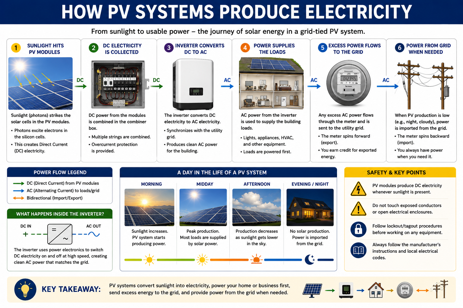
A photovoltaic cell is a semiconductor device that converts energy from sunlight directly into electrical energy. Individual cells are electrically connected and packaged together to form a PV module, commonly called a solar panel. Modules can then be connected together to form larger electrical circuits and arrays.
The electricity produced by conventional PV modules is direct current, or DC. Most building electrical systems and utility grids operate with alternating current, or AC, so PV systems normally use power-electronic equipment called an inverter to convert the DC power into usable AC power.
PV Cell
The basic semiconductor device that converts solar radiation into electrical energy.
PV Module
A group of interconnected photovoltaic cells packaged into the field-installed component commonly called a solar panel.
PV Array
Multiple modules electrically and mechanically arranged to provide the required amount of solar generation.
Inverter
Power-electronic equipment that converts PV-generated DC electricity into AC electricity compatible with the electrical system it serves.
Not Every Solar Collector Produces Electricity
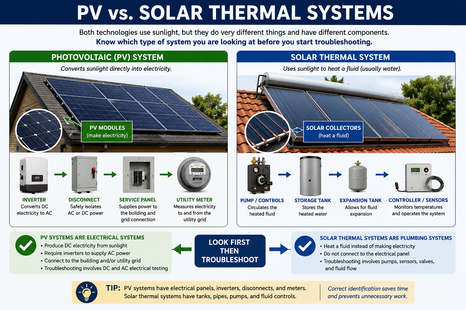
Technicians may encounter equipment on a roof or property that collects solar energy but is not part of a photovoltaic electrical system. Photovoltaic equipment converts sunlight into electricity. Solar thermal equipment captures solar energy as heat and transfers that heat to water, another liquid, or another thermal process.
This course is concerned primarily with photovoltaic electrical systems. Identifying the type of solar equipment before beginning an inspection prevents confusion and helps establish which electrical hazards and troubleshooting procedures apply.
Trace Power Through the Installation
A useful way to understand an unfamiliar PV system is to trace the electrical power path. Begin at the source and identify each major piece of equipment encountered before the power reaches the building electrical system or utility connection.
Sunlight Reaches the PV Modules
PV cells within the modules convert a portion of the available solar energy into DC electrical power.
Modules Are Electrically Combined
Depending on the system architecture, modules may be connected into DC strings or connected to module-level power electronics such as microinverters or power optimizers.
Power Is Converted or Conditioned
An inverter converts DC electricity into AC electricity. Where that conversion occurs depends on whether the installation uses a string inverter, microinverters, a hybrid inverter, or another system architecture.
AC Power Enters the Building Electrical System
After conversion, PV-generated AC power is connected through appropriate disconnecting, overcurrent-protection, and distribution equipment to the building electrical system.
Loads, Storage, or the Utility Use the Energy
Depending on the system configuration and operating conditions, PV energy may serve building loads, charge battery storage, or be exported through the utility interconnection.
Do Not Start by Guessing Which Component Failed
A customer may describe the problem as a bad panel, bad inverter, bad battery, or solar system that is not producing. Treat that description as the reported symptom rather than the final diagnosis.
A systematic technician first determines what type of system is installed, what equipment is present, what operating mode the system is in, where electrical power should be present, and what evidence supports moving toward a particular component.
The Process Used Throughout This Course
The same troubleshooting sequence will be used repeatedly as the lessons become more detailed. Following a repeatable process reduces unnecessary measurements and helps prevent a technician from jumping directly to a component replacement without enough evidence.
Identify
Determine the system type, equipment, electrical configuration, ratings, available energy sources, and reported complaint.
Inspect
Look for visible damage, abnormal conditions, wiring problems, environmental concerns, equipment status, and other clues.
Measure
Use the appropriate instrument to measure AC or DC voltage, current, and other electrical conditions at logical test points.
Compare
Compare actual readings with equipment ratings, expected values, operating conditions, monitoring data, and similar circuits.
Continue the process: use the evidence to diagnose the problem, repair or recommend the appropriate service action, and then verify that the system operates correctly afterward.
Think of the Installation as Several Electrical Sections
Breaking a PV system into functional sections makes troubleshooting easier. The exact equipment differs between installations, but most systems can be divided into several recognizable areas.
PV Generation
Modules and arrays are the electrical source. Their output depends on sunlight, temperature, module characteristics, system configuration, shading, and equipment condition.
DC Collection
String wiring, connectors, combiner equipment, disconnects, and related components move DC power toward the inverter in systems that use centralized DC conversion.
Power Conversion
String inverters, microinverters, hybrid inverters, and power optimizers perform different power-electronic functions depending on the system architecture.
AC Distribution
After DC-to-AC conversion, conductors, disconnects, breakers, distribution panels, and service equipment connect PV production to the building electrical system.
Utility Interconnection
Grid-connected systems operate in coordination with utility service and include equipment and protective functions associated with the point of interconnection.
Monitoring & Controls
Inverters, gateways, communications networks, meters, and monitoring platforms may provide production information, operating status, fault codes, and other diagnostic evidence.
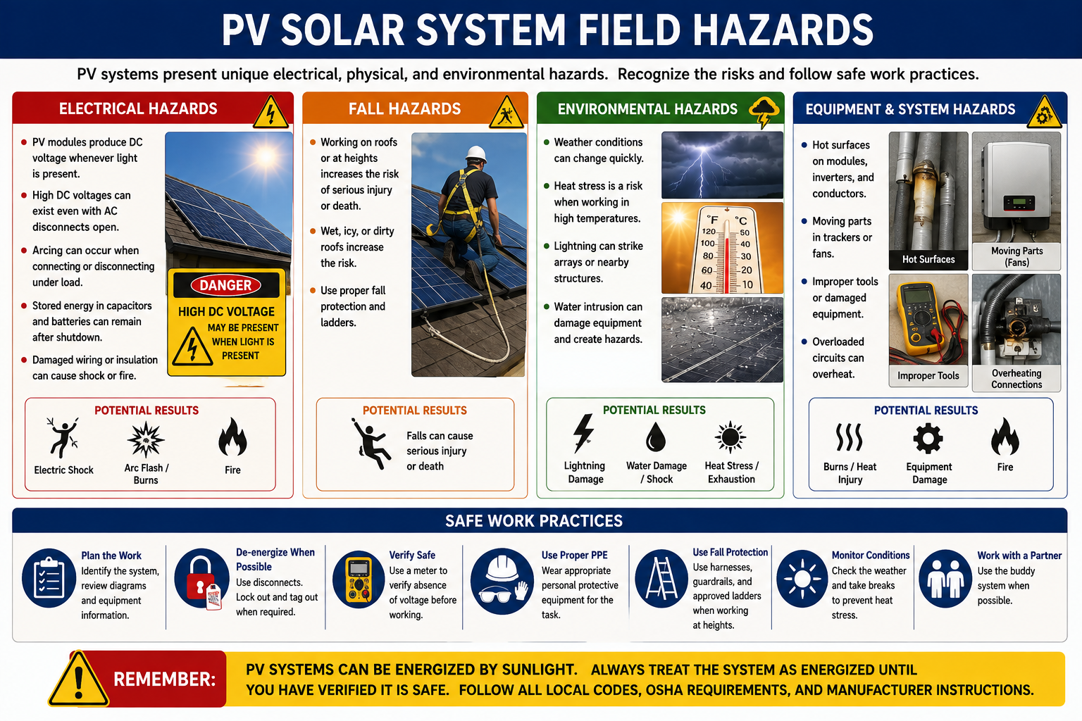
PV Systems Present Electrical and Physical Hazards
Solar electrical work involves hazards familiar to electricians, including shock, arc-flash exposure, energized equipment, falls, overhead lines, damaged conductors, weather, heat, lifting, and difficult access. PV systems also require the technician to remember that modules may generate electrical power whenever sufficient light reaches them.
Opening an AC breaker or shutting down an inverter does not automatically prove that every conductor in the PV installation is de-energized. System configuration, module-level equipment, multiple power sources, battery storage, and manufacturer-specific shutdown procedures must all be considered before work begins.
Identify Every Energy Source Before Work Begins
PV modules are electrical sources whenever they receive sufficient light. A grid-connected installation may also have utility power available, and battery-equipped systems may contain stored electrical energy even when neither PV generation nor utility power is available.
Use appropriate safe-work practices, properly rated test equipment, required PPE, lockout/tagout procedures where applicable, manufacturer instructions, and applicable electrical and workplace-safety requirements. Never assume equipment is de-energized solely because a switch, breaker, or inverter has been turned off.
What You Should Take From This Lesson
PV Means Electrical Generation
Photovoltaic cells convert solar radiation into DC electrical energy, and modules combine many cells into a practical field-installed power source.
The Inverter Connects DC Generation to an AC System
PV-generated DC electricity must normally be converted to AC electricity before it can supply conventional building loads or interact with the utility grid.
The Complete System Matters
Modules, wiring, connectors, inverters, disconnects, distribution equipment, monitoring, utility interconnection, and optional battery equipment must be considered as parts of one operating system.
Troubleshooting Begins With Identification
Determine what is installed and how power should flow before deciding which measurements to make or which component might have failed.
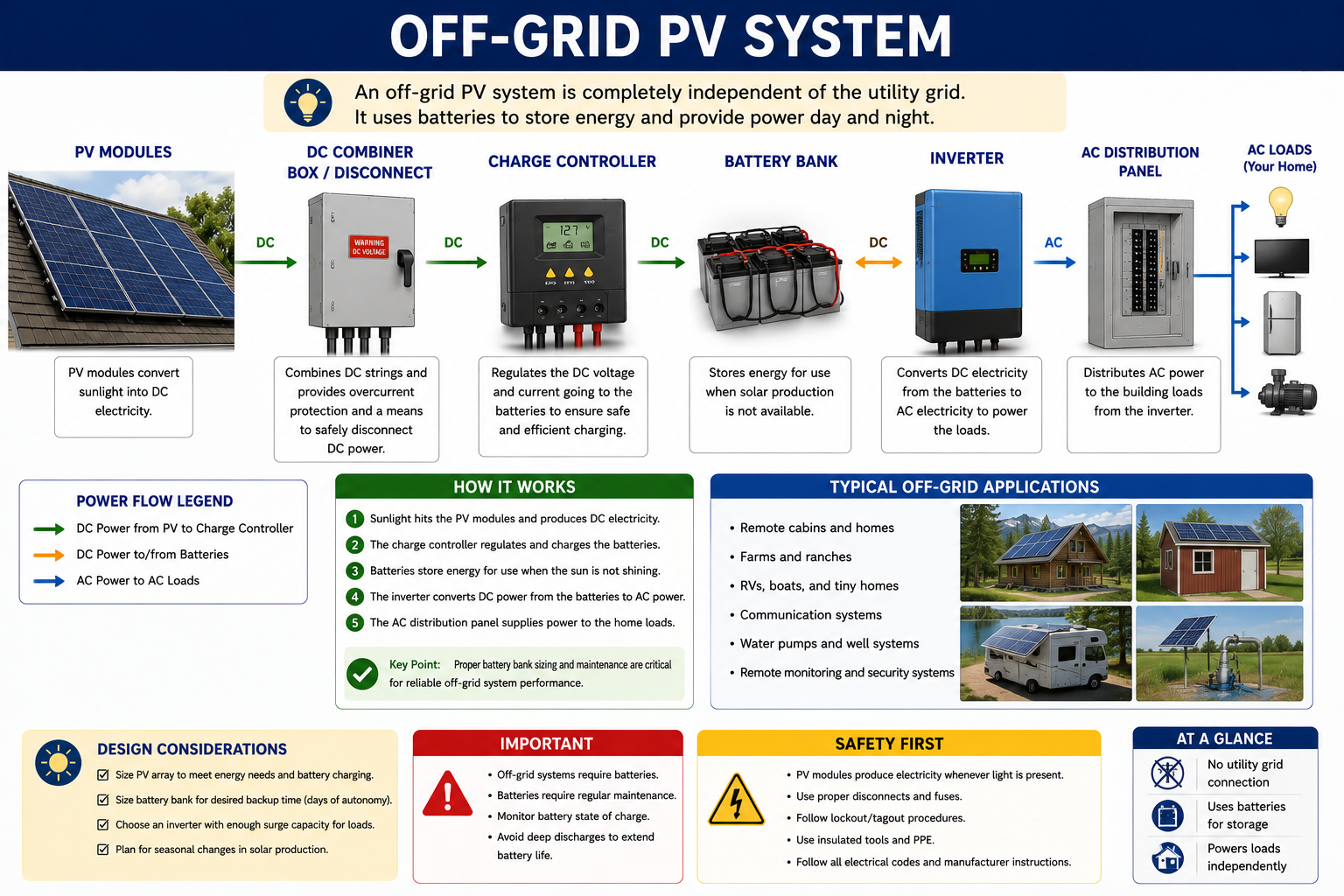
Grid-Tied, Battery-Backed, and Off-Grid PV Systems
The next lesson compares the major PV configurations technicians encounter in the field. Understanding whether the installation depends on the utility, includes battery backup, or operates independently from the grid changes both expected operation and the troubleshooting path.
PV Solar System Fundamentals
Return to the Part I landing page for all six PV Solar System Fundamentals lessons.
Technical References
This lesson is based on established photovoltaic fundamentals and electrical-safety guidance from the U.S. Department of Energy and the Occupational Safety and Health Administration.