Introduction to Air-Distribution Systems
Heating and cooling equipment cannot condition a building correctly unless air moves through the equipment, travels through the supply ducts, enters the occupied spaces, and returns to the equipment through a complete circulation path.
This lesson introduces the residential forced-air system as one connected assembly. It explains the roles of the blower, filter, heating and cooling components, supply and return ducts, registers, grilles, and occupied spaces while establishing the airflow concepts used throughout the remainder of this section.
What You Will Learn
By the end of this lesson you should be able to:
Trace the complete airflow path.
Follow air from the occupied space through the return system, equipment, supply system, and back into the rooms.
Separate supply from return.
Identify the purpose and normal airflow direction of supply ducts, return ducts, registers, and grilles.
Identify the major air-side components.
Explain how the filter, blower, heating section, cooling coil, plenums, ducts, and terminals contribute to air distribution.
Relate airflow to equipment performance.
Recognize how airflow affects heating, cooling, humidity removal, comfort, noise, efficiency, and equipment reliability.
Use airflow terminology correctly.
Describe airflow in cubic feet per minute and distinguish total equipment airflow from airflow delivered to an individual room.
Recognize the system approach.
Understand why a technician must evaluate the equipment, ductwork, filters, terminals, controls, and building together.
Air Must Leave the Equipment and Return to It
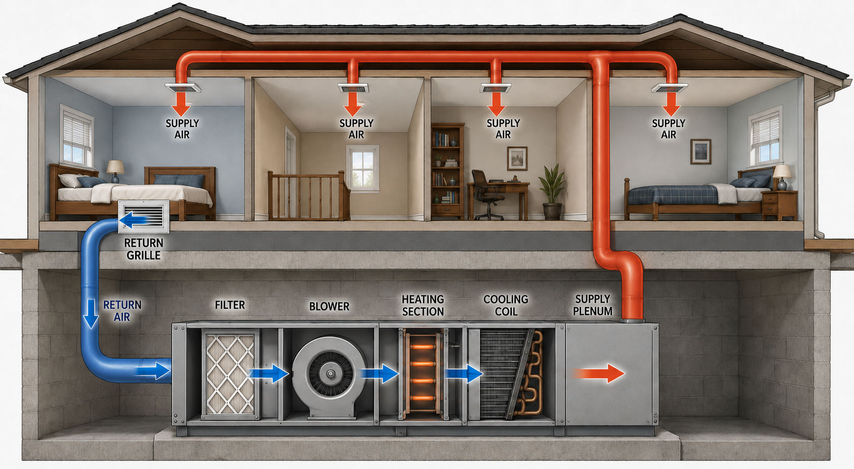
1. Air Leaves the Occupied Space
Room air enters a return grille and begins traveling toward the heating and cooling equipment.
2. Return Ducts Carry the Air
The return duct system provides a path from the occupied spaces to the inlet side of the equipment.
3. The Filter Removes Particles
The filter removes particles from the circulating airstream while also creating resistance that the blower must overcome.
4. The Blower Moves the Air
The blower creates the pressure difference needed to move air through the equipment and connected duct system.
5. The Equipment Conditions the Air
The air passes through the applicable heating or cooling components, where heat and sometimes moisture are transferred.
6. Supply Ducts Distribute the Air
The supply plenum, trunk ducts, and branches carry conditioned air toward the occupied spaces.
7. Terminals Deliver the Air
Registers and diffusers discharge the supply air into the rooms and help establish its direction, spread, and mixing.
8. The Cycle Continues
The delivered air mixes with room air, absorbs or releases heat as conditions require, and eventually returns to the equipment.
A powerful blower cannot compensate for a disconnected duct, blocked return path, severely restricted filter, closed damper, collapsed flexible duct, or incorrectly selected terminal. Every part of the circulation path affects the rest of the system.
Two Sides of One Circulation System
Air Travels Toward the Equipment
Return grilles and return ducts collect air from the building and carry it to the inlet side of the filter and blower assembly.
Air Travels Away from the Equipment
Supply plenums, trunks, branches, registers, and diffusers distribute conditioned air from the equipment to the occupied spaces.
Return Grille
A return grille covers an opening through which room air enters the return system. It normally does not include an operator-adjustable airflow damper.
Return Duct
A return duct carries air from one or more return grilles to the equipment inlet and normally operates at a pressure below the surrounding equipment area when the blower runs.
Supply Duct
A supply duct carries conditioned air away from the equipment and normally operates at a pressure above the surrounding area when the blower runs.
Supply Register or Diffuser
A register or diffuser delivers air into a room and influences the direction, spread, velocity, mixing, and noise of the discharge air.
Terminology note: A register normally includes an integral damper, while a grille is a covering through which air passes without that type of adjustable damper. In everyday field use, the terms are sometimes applied less precisely.
The Blower Establishes the Pressure Difference
Inlet Side
The operating blower lowers pressure at its inlet relative to the equipment area, causing return air to move toward the blower.
Outlet Side
The blower increases pressure at its outlet so air moves through downstream equipment components and the supply duct system.
System Resistance
Filters, coils, heat exchangers, ducts, fittings, dampers, grilles, and registers resist airflow and affect where the blower operates on its performance curve.
Operating Point
Actual airflow results from the interaction between blower performance and the resistance of the complete connected air system.
The blower creates a pressure difference that moves existing air through an available path. If the path becomes more restrictive, airflow may decrease, blower power may change, or a controlled blower may increase speed in an attempt to maintain its airflow target.
Equipment and Ductwork Cannot Be Evaluated Separately
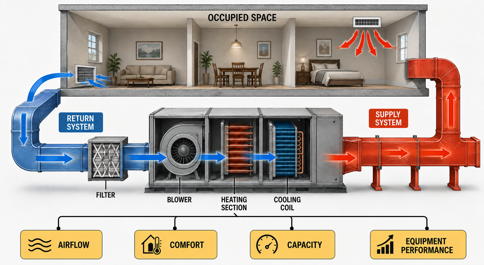
Equipment
The blower, heating section, cooling coil, filter, cabinet, and controls establish the conditions under which air can be heated, cooled, dehumidified, and circulated.
Duct System
The supply and return ducts determine how much resistance the blower encounters and whether conditioned air reaches the intended spaces.
Occupied Space
Room loads, doors, return paths, registers, furnishings, solar exposure, infiltration, and occupant activity affect the air-distribution results.
Controls
Thermostats, zoning systems, fan settings, equipment staging, and variable-speed controls determine when and how the system operates.
A compressor, furnace, heat pump, or blower can operate while the building receives inadequate or uneven airflow. System performance must be evaluated at the equipment and in the occupied spaces.
Airflow Is Commonly Expressed in CFM
Cubic Feet per Minute
CFM describes the volume of air moving past a point during one minute.
Total Air Through the Equipment
Total system airflow describes the volume passing through the air-handling equipment under the measured operating conditions.
Air Through One Duct
Branch airflow describes the portion of total airflow carried by an individual supply or return branch.
Air Delivered to a Space
Room airflow is the volume delivered through one or more terminals serving a particular occupied space.
Avoid universal airflow assumptions: Required airflow depends on equipment design, operating mode, blower performance, sensible and latent loads, altitude, duct conditions, and manufacturer requirements. A familiar rule of thumb is not a substitute for equipment data and field measurements.
Airflow Affects Cooling and Moisture Removal
Sensible Cooling
Air moving across the evaporator transfers sensible heat to the refrigerant, reducing the air’s dry-bulb temperature.
Latent Cooling
When the coil surface is below the air’s dew point, water vapor condenses on the coil and latent heat is removed from the airstream.
Insufficient Airflow
Low airflow can reduce delivered capacity, lower evaporator temperature, contribute to icing, reduce room circulation, and create misleading refrigeration-system symptoms.
Excessive Airflow
Excessive airflow can increase noise, affect temperature change, alter moisture removal, and produce unacceptable air velocity at ducts and terminals.
A large or small temperature difference across cooling equipment can provide useful evidence, but it does not independently prove the airflow rate. Refrigerant conditions, indoor air conditions, equipment capacity, measurement location, and system operation must also be considered.
Airflow Also Controls Heating Performance
Furnace Heating
Air absorbs heat as it passes across the heat exchanger. Airflow must keep the temperature rise within the equipment manufacturer’s specified range.
Heat-Pump Heating
The indoor coil transfers heat from the refrigerant to the airstream, and airflow affects delivered temperature, capacity, refrigerant operation, and defrost recovery.
Electric-Resistance Heat
Airflow carries heat away from the electric elements and is required for proper temperature control and limit protection.
Restricted Heating Airflow
Insufficient airflow can increase furnace temperature rise, contribute to limit cycling, overheat components, reduce comfort, and shorten equipment life.
The same duct system may serve cooling, heat-pump heating, furnace heating, electric heat, ventilation, and continuous-fan operation. Blower settings and acceptable performance must be evaluated in every applicable operating mode.
Duct Performance Affects the Entire Building
Comfort
Incorrect room airflow, poor air mixing, inadequate return paths, and duct losses can produce rooms that remain too warm, too cool, drafty, or stagnant.
Capacity
The building receives useful heating or cooling only when conditioned air reaches the occupied spaces at the required airflow and condition.
Humidity Control
Cooling airflow affects coil temperature, condensate formation, equipment runtime, room mixing, and the system’s ability to remove moisture.
Noise
High velocity, restrictive terminals, sharp fittings, closed dampers, undersized ducts, air leakage, and blower operation can create objectionable sound.
Energy Use
Excessive resistance, leakage, poor insulation, incorrect airflow, and ineffective distribution can increase fan energy and equipment runtime.
Equipment Reliability
Airflow defects can contribute to evaporator icing, furnace limit trips, motor stress, compressor problems, condensation, and repeated service complaints.
Air Delivered to a Space Needs a Return Path
Air Can Circulate
Supply air entering a room can travel through a dedicated return, transfer grille, jumper duct, open doorway, or another intentionally designed path back to the equipment.
Room Pressure Can Increase
A closed room receiving supply air without an adequate return path can become positively pressurized relative to adjacent areas, reducing delivered airflow and increasing uncontrolled leakage.
For circulation to continue, air supplied to an occupied space must leave that space through a return path, transfer path, exhaust path, leakage path, or some combination of those paths.
Trace the System Before Measuring It
- Identify the equipment type and every applicable heating, cooling, and fan operating mode.
- Locate the air handler, furnace, fan coil, packaged unit, or rooftop unit.
- Identify the filter location and determine whether more than one filter is installed.
- Trace the return grilles and return ducts to the equipment inlet.
- Trace the supply plenum, trunks, branches, registers, and diffusers away from the equipment.
- Look for dampers, zoning components, transfer paths, access panels, and concealed transitions.
- Inspect for visible restrictions, leakage, disconnected ducts, damaged insulation, crushed flex duct, and closed terminals.
- Determine whether the complaint affects the entire system, one operating mode, one duct branch, or one occupied space.
- Record the original equipment settings and operating conditions before making changes.
- Select measurements that can confirm or eliminate the suspected causes.
Changing blower speed before identifying restrictions, filter condition, coil condition, equipment settings, duct defects, and manufacturer requirements can hide evidence or create a different problem. Establish the original condition first.
Errors to Avoid
“If air comes from the registers, airflow is correct.”
Air movement at a register does not establish total equipment airflow, room airflow, system balance, or acceptable pressure.
“The blower forces the same airflow through any duct.”
Actual airflow depends on blower performance, blower settings, system resistance, controls, and operating conditions.
“The return side is less important.”
An undersized, restricted, leaking, or incomplete return system can limit total airflow and affect every supply outlet.
“A larger blower setting fixes a small duct.”
Increasing blower speed may increase pressure, noise, leakage, and motor demand without providing an acceptable correction for restrictive ductwork.
“Heating and cooling always use the same airflow.”
Different operating modes can use different blower settings and have different equipment airflow requirements.
“The duct system only affects comfort.”
Air-distribution problems can also affect capacity, humidity control, energy use, safety controls, component temperature, and equipment reliability.
Can You Trace the Complete Air System?
- In what direction does air travel through a return duct?
- In what direction does air travel through a supply duct?
- What creates the pressure difference that moves air through the system?
- What components commonly create resistance to airflow?
- What does CFM describe?
- Why does airflow through cooling equipment affect humidity removal?
- How can insufficient airflow affect furnace operation?
- Why does a closed room receiving supply air need a return or transfer path?
- Why does air movement at a register not prove correct system airflow?
- Why should blower speed not be changed before the original condition is documented?
- How does total equipment airflow differ from room airflow?
- Why must the equipment and duct system be evaluated as one connected system?
What You Should Have Learned
A complete forced-air system carries air from the occupied space through the return system and equipment before delivering it through the supply system.
Return air travels toward the equipment, while supply air travels away from the equipment and into the occupied spaces.
The blower creates the pressure difference that moves air, while the connected system determines the resistance the blower encounters.
Filters, coils, heat exchangers, ducts, fittings, dampers, grilles, and registers all affect airflow.
CFM describes airflow volume, but total system airflow, branch airflow, and room airflow are different measurements.
Airflow affects cooling, heating, humidity removal, comfort, noise, energy use, and equipment reliability.
Every occupied space receiving supply air needs an adequate path through which air can leave and return toward the equipment.
A reliable diagnosis evaluates equipment operation, blower performance, ductwork, filters, terminals, controls, and the building together.