Electrical Testing and Troubleshooting Battery Systems
Battery-system troubleshooting requires more than checking battery voltage. A storage system depends on generation, charging, stored energy, power conversion, transfer equipment, metering, communications, and connected loads. A failure in any one of these areas can produce symptoms that appear to be a battery problem.
This lesson develops a systematic field-testing process for qualified technicians. The objective is to determine which part of the system is not performing as expected, then narrow the diagnosis using appropriate AC and DC measurements, equipment status information, and communications diagnostics.
Troubleshoot the System, Not Just the Battery
A complaint such as “the battery isn’t charging” does not identify the failed component. The battery may be functioning normally while PV production is unavailable, charging is disabled, power-conversion equipment is offline, a disconnect is open, communications have failed, or system controls are intentionally preventing charging.
The same principle applies to backup-power complaints. A fully charged battery cannot supply backup loads if transfer equipment does not isolate the utility, the inverter cannot establish the backup source, communications are unavailable, or the connected load exceeds the system’s capability.
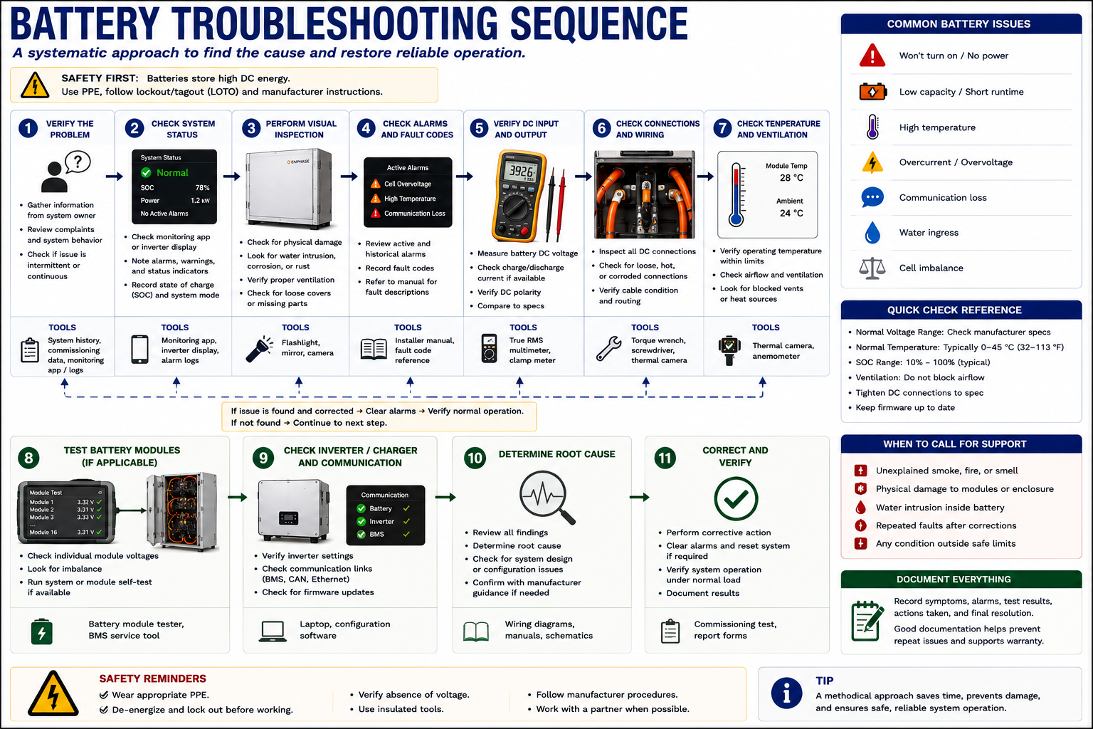
Complete the Safety and Visual Assessment First
Electrical troubleshooting begins only after the visual inspection developed in Lesson 19 has established that conditions are appropriate for continued work.
Do not proceed with routine electrical testing when the battery or associated equipment shows a stop-work condition such as smoke, fire, significant swelling, severe overheating, evidence of venting, major physical damage, significant water exposure, active arcing, or another potentially hazardous abnormal condition.
Technician principle: Electrical testing is the next step only when the equipment condition permits electrical testing.
Define What Is Actually Not Working
Begin by translating the reported problem into a specific operating condition. “The battery doesn’t work” is not sufficiently specific for systematic diagnosis.
Not Charging
Determine whether the battery should be charging under the present PV production, utility condition, state of charge, and operating mode.
Not Discharging
Determine whether the system is presently configured to discharge and whether sufficient load exists to require battery power.
No Backup Power
Determine whether all backup loads are unavailable or whether the complaint involves only one circuit or load.
Battery Offline
Determine whether the battery is electrically unavailable, intentionally shut down, in a protective state, or simply missing from communications.
Low Runtime
Compare actual load, available state of charge, reserve settings, and usable battery capacity before assuming a storage failure.
Low PV Production
Determine whether the symptom is actually a PV problem or whether battery-system controls are intentionally limiting PV production.
Preserve the Evidence Before Changing Anything
Record available information before resetting equipment, cycling disconnects, clearing faults, changing operating modes, or restarting the system.
Useful information can include battery state of charge, charging or discharging power, PV production, building load, utility import or export, operating mode, backup reserve, active fault codes, inverter status, battery status, transfer-equipment status, and communications condition.
Record first. Reset later. Restarting equipment can temporarily remove the symptom and erase information that would have helped identify the cause.
Determine What the System Should Be Doing
A measurement has little diagnostic value unless the technician knows what condition is expected. Determine the current operating mode and establish the expected power path before connecting test instruments.
For example, if the battery is at its configured reserve level, the system may correctly refuse to discharge during normal grid-connected operation. If the battery is already fully charged, zero charging current can be completely normal.
Troubleshooting begins with the difference between expected operation and actual operation.
Divide the System Into Functions
Generation
Is sufficient PV or other permitted charging-source power available?
Charging
Is power being transferred toward the battery when charging should occur?
Storage
Is the battery online and within conditions that permit charging or discharging?
Conversion
Is the inverter or power-conversion equipment operating correctly?
Transfer
Can the system correctly transition between utility-connected and backup operation?
Communications
Are the required devices exchanging valid operating and control information?
Metering
Does the control system have accurate information about utility, load, PV, and battery power flow?
Loads
Are the affected loads actually backed up, and are they within the system’s operating capability?
Use AC Measurements to Verify the Grid, Conversion Equipment, and Loads
AC measurements can establish whether utility voltage is available, whether battery power-conversion equipment is producing AC, whether the backup system has established an AC source, and whether power is reaching the intended loads.
The exact test points depend on the system architecture. Use the equipment documentation and the system map established during inspection to determine appropriate accessible measurement locations.
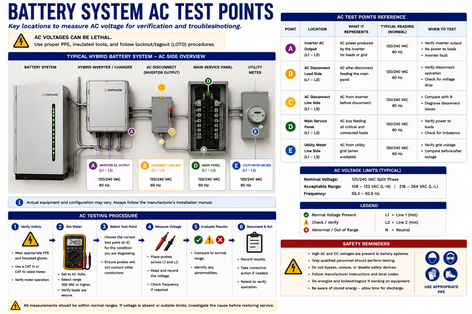
Verify the Source Before Diagnosing Downstream Equipment
When utility power should be present, verify that the expected voltage exists at an appropriate upstream location. A utility-side or distribution problem can prevent normal battery-system operation even though the storage equipment itself is functional.
Depending on the system, loss or abnormality of utility voltage may cause the equipment to transition to backup, remain offline, or report a grid-related fault.
Measure the Conductors Appropriate to the System
Verify the expected line-to-line and line-to-neutral voltages where applicable to the installed system. Do not assume the nominal voltage or phase configuration from equipment appearance alone.
Compare measurements with equipment ratings, system documentation, and measurements at adjacent test points. The objective is to determine where the expected AC condition is present and where it disappears.
Current Shows Whether Power Is Actually Moving
Correct voltage alone does not establish that useful power is being transferred. When appropriate, current measurements can help determine whether the battery system is charging from the AC side, discharging toward loads, or remaining idle.
Because battery power flow is bidirectional, establish the expected direction of energy before interpreting current measurements.
Voltage tells you that an electrical potential exists. Current helps establish whether power is actually being transferred.
Test Both Sides of the Backup Boundary
During a backup complaint, determine whether utility power is present, whether the system has recognized the outage condition, whether the utility has been isolated as required, and whether an AC source has been established on the backup side.
A useful diagnostic distinction is whether backup power fails to exist at the output of the power-conversion or transfer equipment or whether backup power exists there but fails to reach a particular downstream load.
Use DC Measurements Only at Appropriate Field Test Points
DC testing may be useful in systems with externally accessible battery circuits or DC-coupled architecture. Test only locations intended for field measurement and follow the equipment manufacturer’s procedures.
Do not interpret this lesson as authorization to open sealed battery packs or access internal battery cells, modules, bus structures, or other areas outside normal field-service procedures.
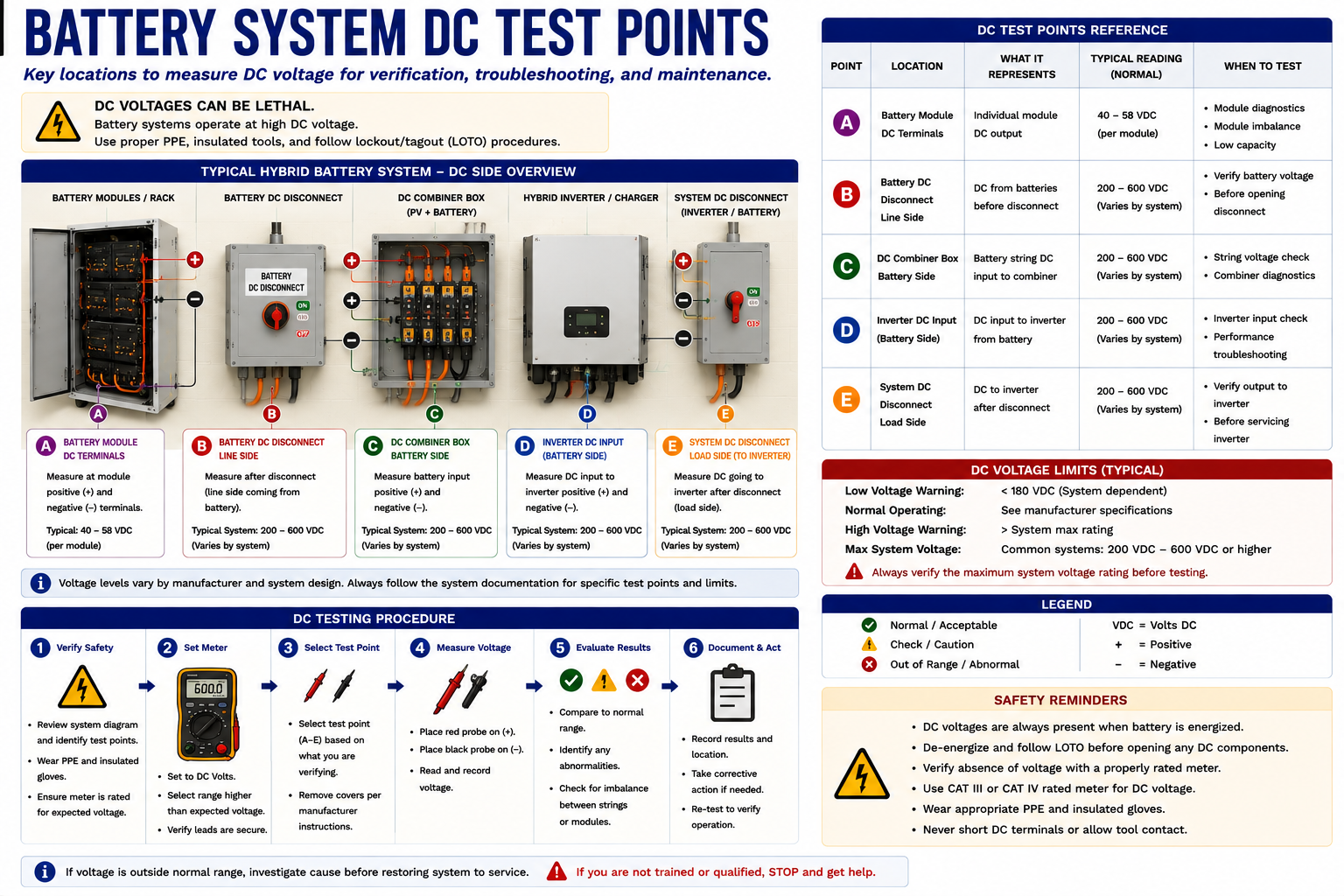
Verify the Expected DC Condition at the Appropriate Location
Where manufacturer procedures provide an accessible DC measurement point, voltage can help determine whether the expected battery or DC-bus condition is present.
Interpret the measurement using the equipment’s actual operating range rather than assuming that a battery has one fixed nominal voltage. Battery-system DC voltage can vary substantially with chemistry, architecture, state of charge, operating condition, and product design.
Direction Matters During Charging and Discharging
When DC current is an approved and useful field measurement, establish whether current should be moving toward the battery or away from it.
A battery showing voltage but no current may be fully charged, at reserve, idle because of system configuration, limited by the BMS, disconnected by internal controls, prevented from operating by another fault, or simply not being commanded to charge or discharge.
Do Not Use Battery Voltage Alone to Judge Battery Condition
Battery voltage is only one piece of information. Modern energy-storage equipment uses battery-management systems, internal contactors, power electronics, communications, state-of-charge calculations, temperature monitoring, and protective controls.
Combine approved electrical measurements with equipment status and manufacturer diagnostic information.
Start With the Question: Should the Battery Be Charging?
Before looking for a failed component, confirm that the operating conditions actually call for charging. Check state of charge, reserve settings, operating mode, available PV production, utility conditions, schedules, and any system restrictions.
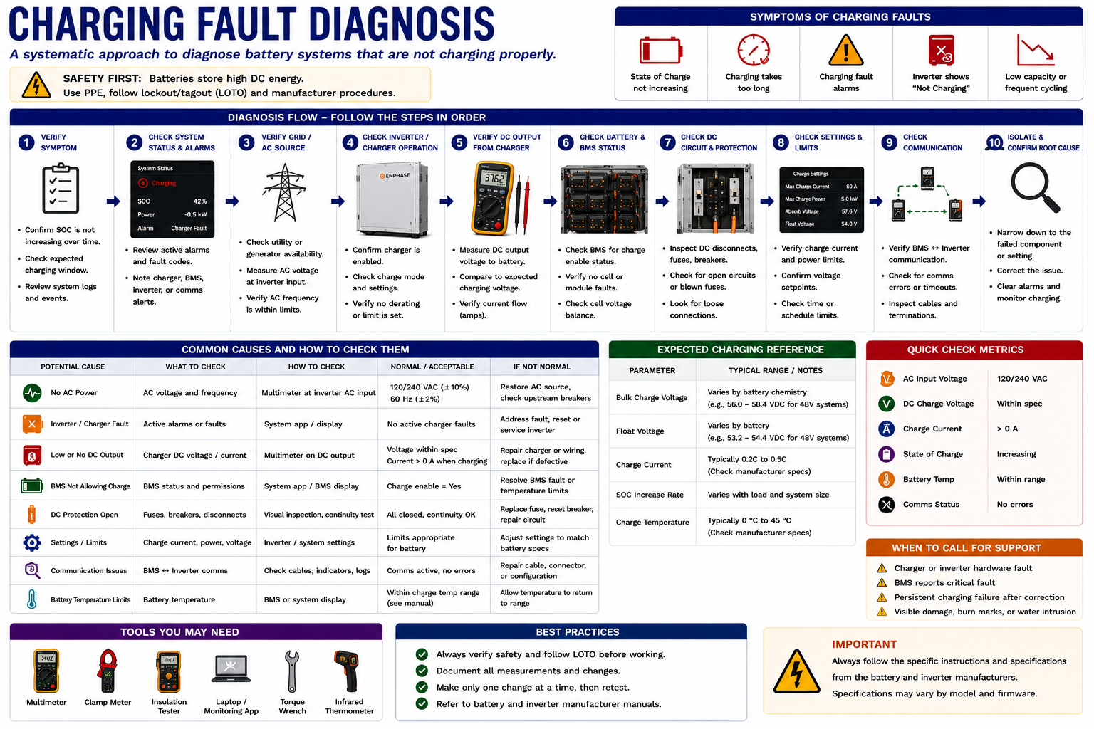
Follow the Charging Path
Confirm Charging Should Occur
Verify operating mode, state of charge, reserve setting, schedule, and other conditions that determine whether charging is commanded.
Verify the Energy Source
Confirm that sufficient PV or other permitted charging-source power is available.
Verify the Electrical Path
Check the relevant disconnects, protective devices, conductors, connections, and accessible test points.
Verify Power Conversion
Determine whether the inverter or charging equipment is operating and transferring energy toward the battery.
Verify Communications
Confirm that required battery, inverter, meter, gateway, and control communications are available.
Evaluate Battery Status
Review BMS status, temperature, state of charge, operating limits, and battery-related faults using approved diagnostic information.
PV Production Is Normal but Battery Charging Is Zero
Suppose the PV system is producing normally and sufficient excess power appears to be available, but battery charging remains at zero.
Do not immediately condemn the battery. Determine whether charging is being commanded. Check state of charge, operating mode, reserve settings, charging limits, power-conversion status, metering, communications, disconnects, and active faults.
The diagnostic process should progressively eliminate possible causes until the failed function is isolated.
Determine Whether the System Should Be Using Battery Power
When the battery does not discharge during normal grid-connected operation, first verify the operating strategy. A battery configured primarily for backup may intentionally remain at or near its reserve level while utility power is present.
If discharge should be occurring, determine whether the battery is available, whether power conversion is enabled, whether load and utility measurements are accurate, and whether the system recognizes a reason to discharge.
Break Backup Operation Into Separate Steps
“No backup power” can result from several independent functions. Determine how far the system progresses through the expected outage sequence.
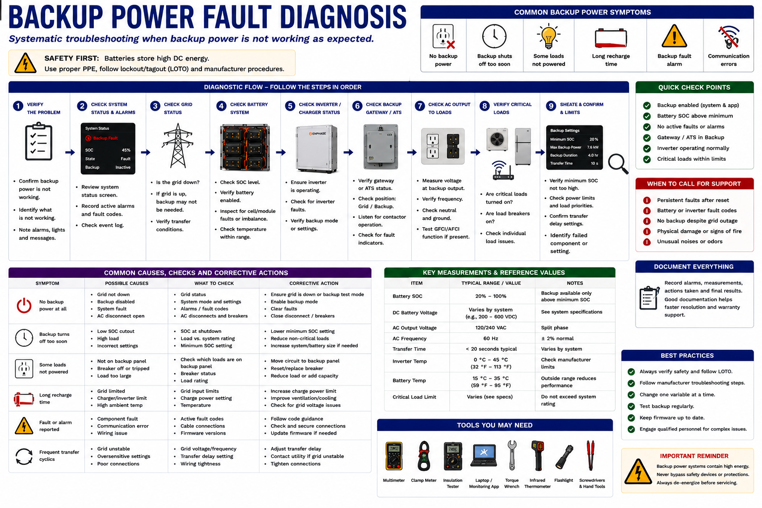
Follow the Outage Sequence
Verify the Utility Condition
Determine whether the system actually sees utility loss or another condition requiring backup operation.
Verify Battery Availability
Check state of charge, battery status, active faults, and whether the battery is available for discharge.
Verify Isolation or Transfer
Determine whether the equipment responsible for separating the backup system from the utility has operated correctly.
Verify the Backup AC Source
Determine whether the battery power-conversion equipment has established the expected AC voltage and frequency for the isolated system.
Verify Backup Distribution
Follow the AC path from the backup source through distribution equipment toward the supported circuits.
Evaluate the Loads
Confirm that the affected circuits are actually included in backup and that the load does not exceed available system capability.
The Scope of the Failure Is an Important Clue
If every backup circuit loses power, investigate equipment common to the entire backup system. If most backup circuits operate but one does not, the fault is more likely downstream of the common backup source.
Check the individual breaker, branch circuit, receptacle, load, or other equipment associated with the affected circuit before diagnosing the battery system itself.
Diagnostic principle: A system-wide symptom suggests a common failure point. A single-load symptom suggests a localized problem.
Backup Power Can Fail Because the Load Is Too Large
Battery state of charge describes available stored energy; it does not establish that the system can supply unlimited instantaneous power.
If backup operation begins and then stops when a large load starts, investigate total load, starting current, inverter power limits, load-control operation, and system fault information.
A fully charged battery can still be unable to support a load that exceeds the power capability of the system.
A Communications Fault Can Look Like a Power Fault
Battery systems rely on communications to exchange operating limits, battery condition, meter data, utility status, commands, and fault information. A device that disappears from the network may stop participating in system operation even though its power wiring remains intact.
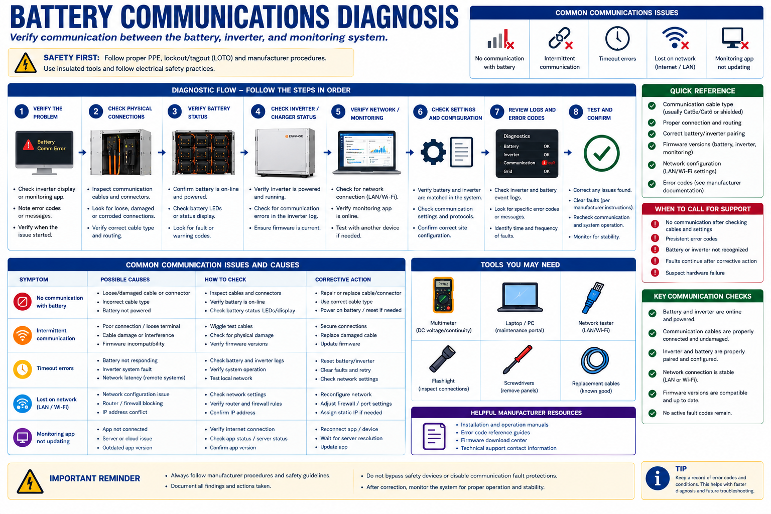
Start With Device Power, Then Follow the Information Path
Is the Device Powered?
A device cannot communicate normally if its required electrical supply is absent.
Is the Physical Communication Path Intact?
Inspect accessible communications wiring, connectors, network equipment, antennas, and other relevant hardware.
Is the Gateway or Controller Online?
Determine whether the problem affects one device or the communications system more broadly.
Is the Device Detected?
Use approved local or manufacturer diagnostic tools to determine whether the device is recognized by the system.
Is Configuration Correct?
Verify addressing, pairing, commissioning, meter assignments, current-sensor configuration, and other applicable settings.
Verify Restored Communication
Confirm that the device remains online and that normal system operation returns after the communications problem is corrected.
Bad Information Can Cause Correct Hardware to Behave Incorrectly
The control system may use current transformers or meters to determine PV production, building consumption, utility import and export, and battery power.
If a sensor is installed around the wrong conductor, oriented incorrectly, assigned to the wrong measurement channel, disconnected, or configured incorrectly, the system may receive inaccurate information about power flow.
This can cause unexpected charging, failure to charge, unexpected discharge, incorrect monitoring data, or other abnormal behavior even when the battery and inverter are electrically functional.
Monitoring Should Agree With the Physical System
Compare system-reported values with field measurements when appropriate. Large unexplained differences between monitored power flow and actual electrical measurements should lead the technician to investigate metering, sensor orientation, communications, configuration, or data interpretation.
Do not assume either source is automatically correct. Determine why the two disagree.
Use Fault History and Operating Conditions
Some battery faults disappear before the technician arrives. Review available fault history, event logs, monitoring trends, and customer observations.
Record when the problem occurs and what conditions exist at that time: state of charge, PV production, load, temperature, utility condition, weather, operating mode, and whether a large load had just started.
Patterns can identify conditions that are difficult to reproduce during a short service visit.
Locate the Last Normal Point and the First Abnormal Point
This troubleshooting principle applies equally well to AC power, DC power, communications, and system operating sequences.
If the expected condition exists at one test point but not at the next, focus on the conductors, protective devices, controls, connections, or equipment between those points.
This is usually more effective than replacing components based on the symptom alone.
Use a Repeatable Battery Troubleshooting Process
Verify Safe Conditions
Complete the visual and hazard assessment before electrical testing.
Define the Complaint
Determine exactly which operating function is not performing correctly.
Record Existing Status
Preserve fault codes, state of charge, operating mode, power flow, and communications information.
Determine Expected Operation
Establish what the system should be doing under the current conditions.
Trace the Expected Power Path
Follow charging, discharging, or backup power through the system.
Test at Logical Boundaries
Use appropriate AC and DC measurements to determine where expected electrical conditions disappear.
Verify Communications and Metering
Determine whether system controls are receiving accurate information and whether required devices are communicating.
Isolate the Failed Function
Determine whether the problem is generation, charging, storage, conversion, transfer, communications, metering, or loads.
Prove the Failed Function Before Replacing Equipment
Battery-system components can be expensive, interconnected, and manufacturer-specific. A reported battery fault does not prove that the battery assembly requires replacement.
Use system status, measurements, communications information, manufacturer diagnostics, and the expected power path to establish the failure before making the service decision.
Battery Testing Can Involve Multiple Energized Sources
Qualified technicians performing electrical testing must account for utility AC, PV-generated DC, stored battery energy, inverter-generated AC, and other sources associated with the installed equipment. Some circuits can remain energized after another source has been disconnected.
Use appropriately rated instruments and PPE, verify instrument operation as required by the applicable procedure, identify the expected voltage before testing, follow manufacturer shutdown and service instructions, and make measurements only at locations appropriate for field testing.
Do not open battery assemblies, bypass protective devices, or access internal battery components unless specifically required by an approved manufacturer procedure for qualified service personnel.
What You Should Take From This Lesson
Define the Failed Function
Determine whether the complaint involves charging, discharge, backup operation, communications, or another specific system function.
Know What Should Be Happening
Establish expected operation before interpreting measurements or system status.
Use AC Test Points Systematically
Verify utility conditions, power-conversion output, transfer operation, backup distribution, and loads at logical boundaries.
Use DC Measurements Appropriately
Measure only at approved field test points and interpret battery voltage and current within the context of the complete system.
Follow the Charging Path
Verify charging demand, available energy, electrical path, conversion equipment, communications, and battery status.
Follow the Backup Sequence
Verify utility detection, isolation, battery availability, grid-forming operation, distribution, and connected loads.
Do Not Ignore Communications and Metering
A power system can be electrically intact but unable to operate correctly because the controls have missing or inaccurate information.
Find the Diagnostic Boundary
Locate the last point where operation is normal and the first point where the expected condition is absent.
Prove the Failure Before Replacing Parts
Determine which function or component has actually failed rather than replacing equipment based only on the reported symptom.
Battery Faults, Service Decisions, and Restoration
The final lesson in Part V moves from diagnosis to corrective action. It covers fault-code interpretation, component-versus-system failures, repair or replacement decisions, controlled system restoration, and final verification of charging, discharging, communications, and backup operation.
Battery Energy Storage Systems
Return to the Part V landing page for the complete battery energy-storage lesson sequence.