Battery Safety and Visual Inspection
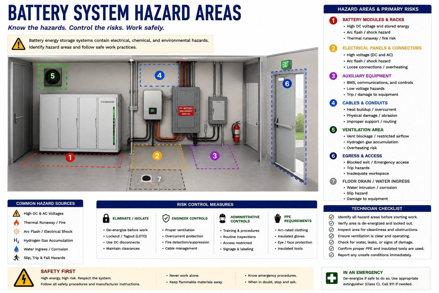
Battery energy-storage systems contain substantial stored electrical energy and introduce hazards that are different from those encountered in a PV-only installation. Before connecting test equipment or opening service-accessible equipment, the technician should evaluate the installation, identify the energy sources and disconnects, and look for physical conditions that could make further work unsafe.
This lesson develops a systematic visual inspection of battery energy-storage equipment. The objective is not to perform internal battery repair. It is to determine whether the installation appears normal, identify visible problems that can guide later troubleshooting, and recognize conditions that require the technician to stop work and follow the appropriate emergency, manufacturer, or site procedure.
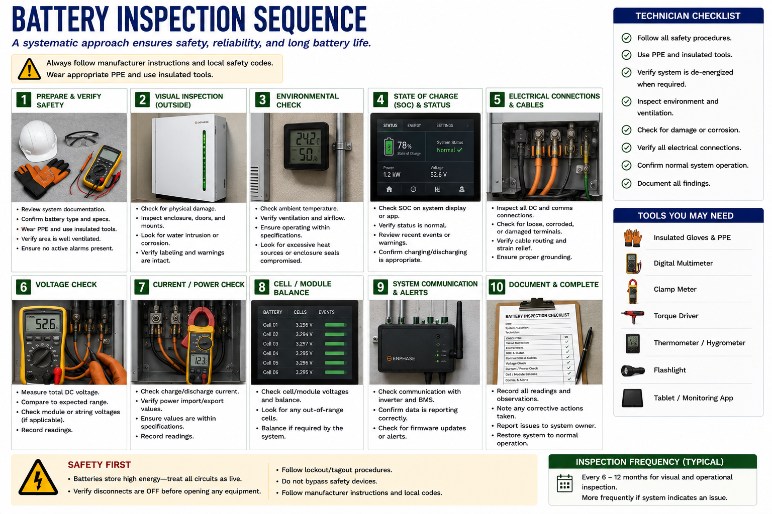
Inspect Before You Test
The systematic troubleshooting method used throughout this course still applies to battery systems: identify the equipment and inspect the system before beginning electrical measurements. With battery storage, however, the visual inspection has an additional purpose. It helps determine whether it is appropriate to continue working around the equipment.
A battery enclosure that is swollen, physically damaged, unusually hot, leaking, smoking, producing an unusual odor, or showing evidence of fire or severe overheating requires a different response from equipment that appears physically normal but reports an operating fault.
The First Decision Is Whether to Continue
A service call may begin with a simple complaint such as “battery offline,” “battery not charging,” or “backup not working.” Do not allow the apparent simplicity of the complaint to bypass the initial safety assessment.
Before electrical testing, determine whether the installation is physically stable and whether there are indications of abnormal battery, electrical, thermal, or environmental conditions.
Technician principle: The visual inspection is not just an opportunity to find the fault. It is also the point at which you decide whether further troubleshooting can be performed safely.
Evaluate the Area Around the Equipment
Begin with the general area rather than immediately opening equipment or operating disconnects. Observe the installation and surrounding environment for anything unusual.
Smoke or Fire
Do not approach battery equipment showing active smoke, fire, or other indications of a potentially serious thermal event.
Unusual Odor
An unexpected chemical, burning, electrical, or other strong unusual odor can indicate an abnormal condition requiring further evaluation before approaching.
Unusual Sounds
Hissing, popping, arcing, or other unexpected sounds can indicate an active electrical or battery problem.
Visible Damage
Impact damage, crushed equipment, damaged enclosures, displaced components, or evidence of a vehicle or structural impact should be evaluated before proceeding.
Water Exposure
Flooding, standing water, significant water intrusion, or water contacting damaged electrical equipment can create additional hazards.
Environmental Conditions
Extreme heat, storm damage, lightning damage, fire exposure, or other unusual environmental conditions can change the appropriate service response.
Know What Equipment You Are Inspecting
Record the battery manufacturer and model and identify the associated inverter, power-conversion equipment, transfer equipment, disconnects, distribution equipment, gateway, and other major components.
Determine whether the system is AC coupled or DC coupled and identify the major energy paths established in Lessons 17 and 18.
This information is particularly important because manufacturer procedures for shutdown, isolation, fault response, and service access can differ substantially between battery systems.
Identify Where Electrical and Stored-Energy Hazards Exist
A PV-plus-storage system can contain several electrical sources at the same time. Utility AC, PV-generated energy, stored battery energy, and inverter-generated AC may be present in different parts of the installation.
Utility Power May Still Be Present
The battery system does not replace the normal utility electrical hazards. Utility voltage may remain present at service equipment, distribution panels, transfer equipment, inverter terminals, disconnects, and other locations.
Turning off a battery does not remove utility voltage from the installation.
Illuminated PV Modules Can Continue Producing Voltage
The PV array remains an independent energy source whenever sufficient light reaches the modules. Battery shutdown does not stop illuminated modules from generating electrical energy.
In DC-coupled systems, PV circuits may enter equipment also associated with the battery system. Identify the actual circuit architecture rather than assuming that shutting down one component removes every DC source.
The Battery Contains Stored Energy
Unlike the PV array, battery energy does not depend on sunlight. A charged battery can remain an electrical energy source at night, during bad weather, and during a utility outage.
A system control showing OFF or STANDBY should not automatically be interpreted as proof that all battery-related conductors and internal components are electrically de-energized.
Important: Operating status and electrical isolation are not the same thing.
Battery Equipment May Energize Circuits When the Utility Is Off
During backup operation, the battery system is specifically designed to energize selected building circuits while utility power is absent.
Never assume that a panel is de-energized merely because the utility main is open or the neighborhood has lost power. Determine whether the panel is within the battery-backed portion of the electrical system.
Look for Changes in the Battery Enclosure
Once conditions permit a closer inspection, examine the exterior of the battery and associated equipment without opening areas that are not intended for routine field access.
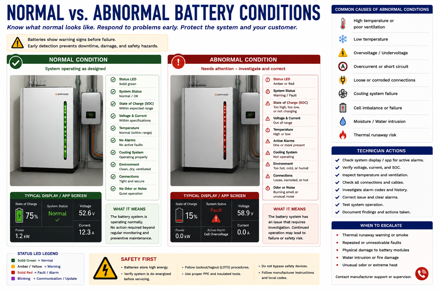
Compare what you see with the expected appearance of the equipment and with other battery units in the installation where applicable.
Establish a Baseline
A normal battery installation should generally have an intact enclosure, secure mounting, unobstructed required clearances, properly supported conductors, intact fittings, readable labels, and no obvious evidence of physical or thermal damage.
Indicator lights or displays should be interpreted using the manufacturer’s documentation rather than by color alone. The same indicator color can represent different conditions on different equipment.
Inspect for Swelling, Distortion, Cracks, and Impact
Look along the surfaces and edges of the battery enclosure for bulging, swelling, separation, unusual gaps, cracked covers, displaced panels, or other distortion.
Physical damage can affect internal battery cells, insulation, bus structures, protective devices, cooling systems, and enclosure integrity even when the equipment remains operational.
Do not attempt to push a swollen enclosure back into shape or open it to determine what is causing the distortion.
Look for Evidence of Abnormal Heating
Inspect for discoloration, melted plastic, distorted components, damaged insulation, burned wiring, overheated terminals, or other evidence of excessive temperature.
Thermal imaging may provide additional information when conditions are appropriate, but a thermal camera should not be used as justification to approach equipment that is already showing signs of a potentially hazardous battery event.
Operating Temperature Affects Battery Behavior
Battery systems monitor temperature and may reduce charging or discharging power when temperatures move toward operating limits. Some equipment may stop operation entirely until acceptable conditions return.
A temperature-related limitation is therefore not automatically evidence of battery failure. Evaluate the ambient environment, equipment ventilation or thermal-management system, manufacturer status information, and any related fault codes.
Keep Required Areas Around Equipment Clear
Inspect the area around battery and power-conversion equipment for blocked ventilation paths, stored materials, vegetation, debris, or other conditions that interfere with required clearances.
Do not assume that an enclosure is designed to tolerate blocked airflow simply because it is outdoor rated. Follow the installation requirements for the specific equipment.
Look for Evidence of Water Intrusion
Inspect enclosures, conduit entries, fittings, wiring paths, and surrounding structures for water entry, corrosion, staining, damaged seals, or other evidence of moisture exposure.
Equipment that has been submerged, flooded, or significantly exposed to water should not be treated as a routine troubleshooting situation. Follow the appropriate manufacturer and electrical safety procedures.
Inspect the External Electrical Connections
Follow accessible wiring associated with the battery system. Look for damaged conduit, unsupported cable, abrasion, impact damage, loose fittings, overheating, animal damage, exposed conductors, improper bends, and other visible defects.
Pay particular attention to areas where conductors enter enclosures, cross structural surfaces, pass through exposed locations, or connect to disconnect and power-conversion equipment.
Locate Them Before You Need Them
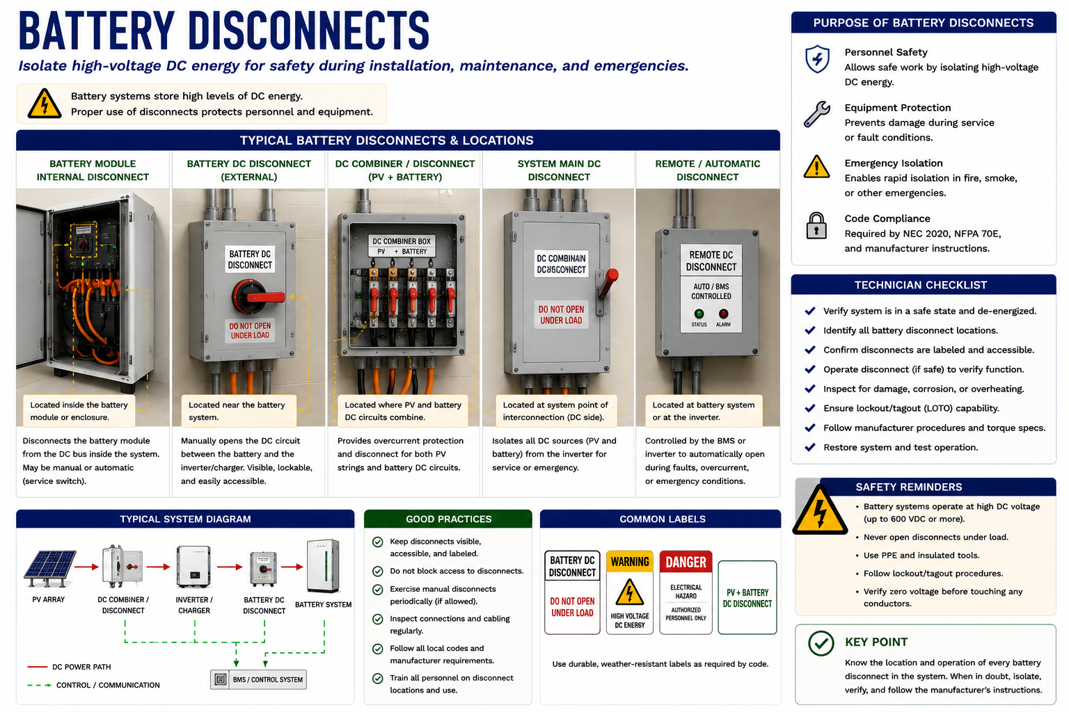
Battery systems can have multiple disconnecting means associated with utility AC, PV circuits, battery circuits, power-conversion equipment, and backup distribution. Some disconnect functions may also be integrated into equipment.
Know What Each Device Actually Disconnects
A disconnect label such as BATTERY, PV, AC, BACKUP, or SYSTEM may provide useful information, but the technician should understand the actual electrical function of the device.
Determine what is on the line and load sides, what source can energize each side, and whether another source can remain present after the disconnect is operated.
Do not assume: Operating one disconnect rarely proves that an entire PV-plus-storage installation is de-energized.
Use the Installation’s Documentation
Inspect equipment labels, directories, warning markings, shutdown instructions, and circuit identification. Compare them with the actual equipment arrangement.
Missing, damaged, inaccurate, or outdated labeling should be documented because it can complicate both normal service and emergency response.
Compare Units With One Another
Systems containing several identical battery units provide useful visual references. Compare enclosure condition, indicator status, wiring, mounting, clearances, and other visible characteristics.
One battery that looks or behaves differently from otherwise identical neighboring units deserves further investigation, provided conditions remain appropriate for continued service work.
Do Not Inspect Only the Battery
A battery complaint can originate outside the battery enclosure. Inspect associated inverters, transfer equipment, backup panels, disconnects, communications devices, meters, current sensors, and distribution equipment.
Look for tripped or open devices, fault indicators, physical damage, loose or damaged wiring, overheating, blocked ventilation, moisture, and other visible abnormalities.
Compare Physical Condition With System Status
Review available local indicators and monitoring information after the physical condition of the equipment has been evaluated. Record battery state of charge, operating mode, active faults, communications status, inverter condition, utility status, and other useful information.
Do not reset faults immediately. Fault information may provide valuable evidence about what occurred before the technician arrived.
Good diagnostic practice: Record the fault before clearing the fault.
Some Findings Change the Service Call Immediately
The technician’s objective is not to complete electrical testing regardless of the conditions encountered. Certain observations should cause routine inspection and troubleshooting to stop.
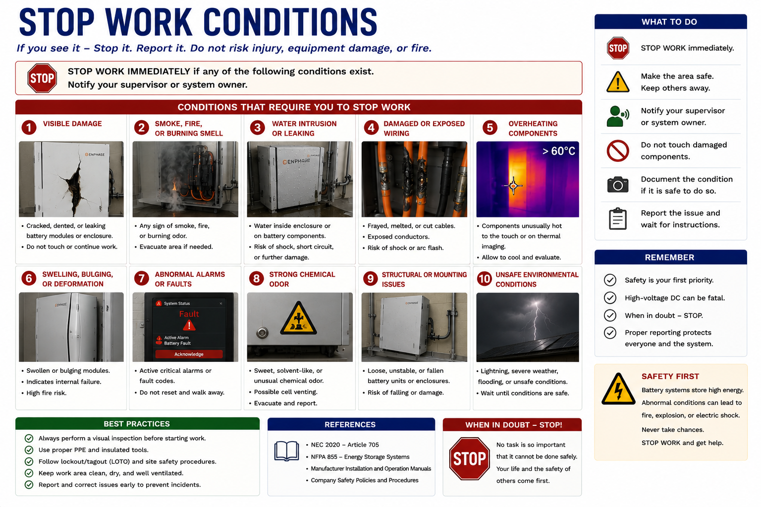
Do Not Continue Routine Testing When Conditions Indicate a Potentially Serious Battery Event
Examples include active smoke or fire, significant swelling or enclosure deformation, severe overheating, evidence of venting, unusual chemical odors associated with an abnormal condition, major impact damage, significant water exposure, active arcing, or other conditions suggesting that approaching or manipulating the equipment could increase the hazard.
Maintain an appropriate safe distance and follow the site’s emergency procedure, manufacturer instructions, and applicable emergency-response requirements.
Internal Inspection Is Not the Next Step
If an abnormal condition appears to originate inside a battery enclosure, opening the enclosure to “see what’s wrong” is generally not an appropriate extension of routine field troubleshooting unless the manufacturer specifically provides a service procedure for qualified personnel to do so.
Internal battery assemblies can contain hazardous voltage, high available fault current, energized bus structures, cells with substantial stored energy, and other hazards not apparent from the exterior.
Do Not Bypass Battery Protection to Continue Testing
Protective shutdowns, contactors, fuses, battery-management controls, interlocks, and other protective functions should not be bypassed merely to determine whether the battery can be forced to operate.
A protective device that prevents operation is part of the diagnostic information. Determine why the protection has operated using approved procedures.
Proceed to Controlled Troubleshooting
If the installation appears physically normal, no stop-work condition is present, the equipment has been identified, and the appropriate service information is available, the technician can proceed to the diagnostic process.
Before connecting test instruments, establish what operating condition is being investigated, determine the expected power path, identify the relevant test points, and follow the manufacturer’s required procedures.
Use the Same Process on Every Battery Service Call
Evaluate From a Distance
Look for smoke, fire, unusual odors, unusual sounds, severe physical damage, water, or other obvious hazards before approaching.
Identify the Equipment
Determine the battery manufacturer, model, architecture, associated power equipment, and installed system configuration.
Identify Energy Sources
Locate utility, PV, battery, backup, and other possible electrical sources.
Inspect Battery Equipment
Look for swelling, deformation, damage, overheating, moisture, blocked clearances, and other abnormal physical conditions.
Inspect Wiring and Associated Equipment
Check external conductors, conduit, fittings, disconnects, inverters, transfer equipment, and distribution equipment.
Locate Disconnects
Determine what each disconnect controls and what energy may remain on either side.
Review Status and Fault Information
Record operating mode, state of charge, communications status, active faults, and other available diagnostic information.
Make the Continue-or-Stop Decision
Determine whether conditions are appropriate for controlled electrical testing or whether routine work should stop.
The Objective Is Controlled Diagnosis, Not Internal Battery Repair
Battery energy-storage equipment contains substantial stored energy. External disconnects, software shutdown commands, and equipment status indicators may control operation without eliminating all electrical or internal stored-energy hazards.
Technicians should follow manufacturer service procedures, use appropriately rated test equipment and PPE, and remain within the field-service scope of the installed equipment. Conditions involving fire, smoke, venting, severe overheating, swelling, major physical damage, significant water exposure, or other potentially hazardous battery conditions require a response appropriate to the condition rather than routine troubleshooting.
What You Should Take From This Lesson
Inspect Before Testing
Evaluate the physical condition of the installation before connecting electrical test equipment.
Identify Every Energy Source
Utility AC, PV generation, battery energy, and backup-generated AC may exist simultaneously in different parts of the system.
Know the Disconnects
Locate each disconnect and understand what it actually isolates rather than relying on the label alone.
Recognize Abnormal Battery Conditions
Swelling, severe overheating, smoke, unusual odors, major damage, water exposure, and other abnormal conditions can change the appropriate service response.
Inspect the Complete System
A battery complaint may originate in power-conversion equipment, transfer equipment, wiring, disconnects, metering, communications, or distribution rather than the battery itself.
Preserve Diagnostic Information
Record fault codes, operating status, and monitoring information before resetting or changing the system.
Know When to Stop
Routine troubleshooting should not continue when conditions indicate a potentially serious battery, electrical, thermal, or environmental hazard.
Stay Within the Service Scope
Do not open internal battery assemblies or bypass protective systems unless specifically required by an approved manufacturer service procedure for qualified personnel.
Electrical Testing and Troubleshooting Battery Systems
The next lesson moves from visual inspection into systematic electrical diagnosis. It follows AC and DC test points and develops troubleshooting paths for charging problems, backup-power failures, and communications faults.
Battery Energy Storage Systems
Return to the Part V landing page for the complete battery energy-storage lesson sequence.