Systematic PV System Diagnosis
Effective PV troubleshooting is not a process of testing components at random. It is a controlled diagnostic sequence that begins with the reported problem, verifies the operating conditions required by the system, and progressively narrows the fault from the complete PV system to a circuit, string, module, or individual component.
This lesson combines the inspection and electrical testing methods developed throughout Parts II and III into a repeatable troubleshooting process. The objective is to locate the actual cause of the problem while avoiding unnecessary testing and unnecessary replacement of good components.
Diagnose the System Before Replacing Parts
A PV system contains many components that depend on one another. A non-producing inverter does not automatically mean the inverter has failed. Low production does not automatically mean the modules are defective. A missing module in a monitoring portal does not automatically mean that the module has stopped generating power.
The technician must determine which required condition is missing and then follow that evidence toward the source of the problem.
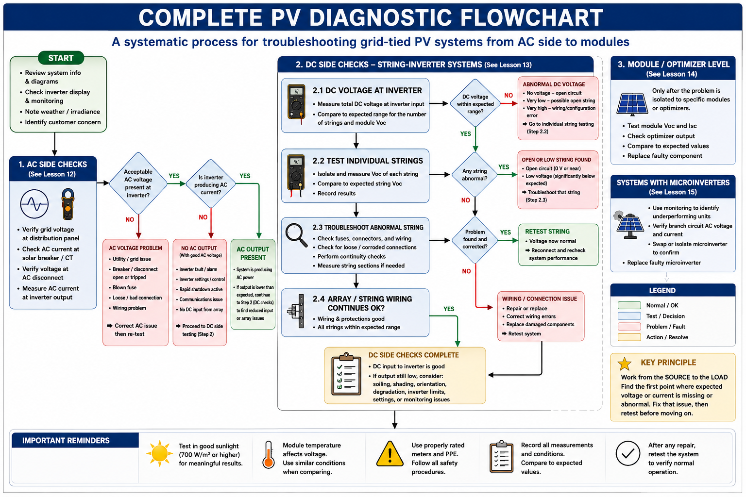
Move From Broad Questions to Specific Tests
Define the Complaint
Determine exactly what the owner, operator, monitoring system, or service record says is wrong.
Verify the Complaint
Confirm that the reported symptom actually exists under the present operating conditions.
Inspect Before Testing
Look for visible damage, disconnected equipment, tripped devices, overheating, environmental problems, and other obvious conditions.
Check System Status
Review inverter status, fault codes, monitoring data, communications, operating mode, and available event history.
Test From the System Toward the Fault
Verify AC conditions, inverter operation, DC inputs, individual strings, and finally module-level equipment as necessary.
Identify the Cause
Do not stop merely because an abnormal measurement has been found. Determine what caused that abnormal condition.
Repair and Verify
Correct the fault, restore the system, and confirm that the original complaint has been resolved.
Do Not Replace the Component That Reports the Problem Until You Know It Caused the Problem
An inverter can report a grid fault caused by the utility supply. It can report a DC fault caused by the array. A monitoring system can report an optimizer problem caused by communications. A breaker can trip because of a fault somewhere else in the circuit.
The device reporting the symptom is not necessarily the device that failed.
Define the Complaint Precisely
Statements such as “the solar isn’t working” or “the system isn’t producing enough” are starting points, not diagnoses. Determine exactly what behavior is being reported.
No Production
The entire PV system appears to produce no usable power.
Low Production
The system operates but produces less energy or power than expected.
Intermittent Operation
Production starts and stops unexpectedly or faults occur repeatedly.
One String Low
One string or inverter input performs differently from comparable circuits.
One Module Offline
Module-level monitoring identifies a single device that is missing or underperforming.
Communications Only
The system may be generating power even though monitoring information is missing or incomplete.
Determine Whether the Complaint Is Reasonable for the Conditions
PV output varies continuously. Before diagnosing low production as a fault, consider the amount of solar energy actually available when the observation or measurement is made.
Time of day, season, cloud cover, haze, smoke, shading, snow, dirt, module temperature, array orientation, and system operating mode can all affect production.
Technician rule: Do not compare today’s instantaneous output with the inverter nameplate and conclude that the system has failed simply because the numbers are different.
Review Monitoring and Fault History
Modern PV equipment can provide valuable diagnostic information before electrical testing begins. Review current status, production history, individual inverter or module-level data where available, active faults, previous faults, communications status, and operating mode.
Monitoring can narrow the investigation, but it should be treated as evidence rather than unquestioned proof of a component failure.
Perform the Visual Inspection
Use the systematic inspection process developed in Part II. Follow the system from the utility and distribution equipment toward the inverter, DC equipment, array wiring, mounting system, and modules.
Look for physical damage, open or tripped equipment, overheated components, loose or damaged conductors, connector problems, corrosion, water intrusion, debris, shading changes, damaged modules, animal damage, and other visible abnormalities.
Start With the Conditions Required for Inverter Operation
When a PV system has no AC output, do not immediately replace the inverter. First determine whether the inverter has everything it needs to operate.
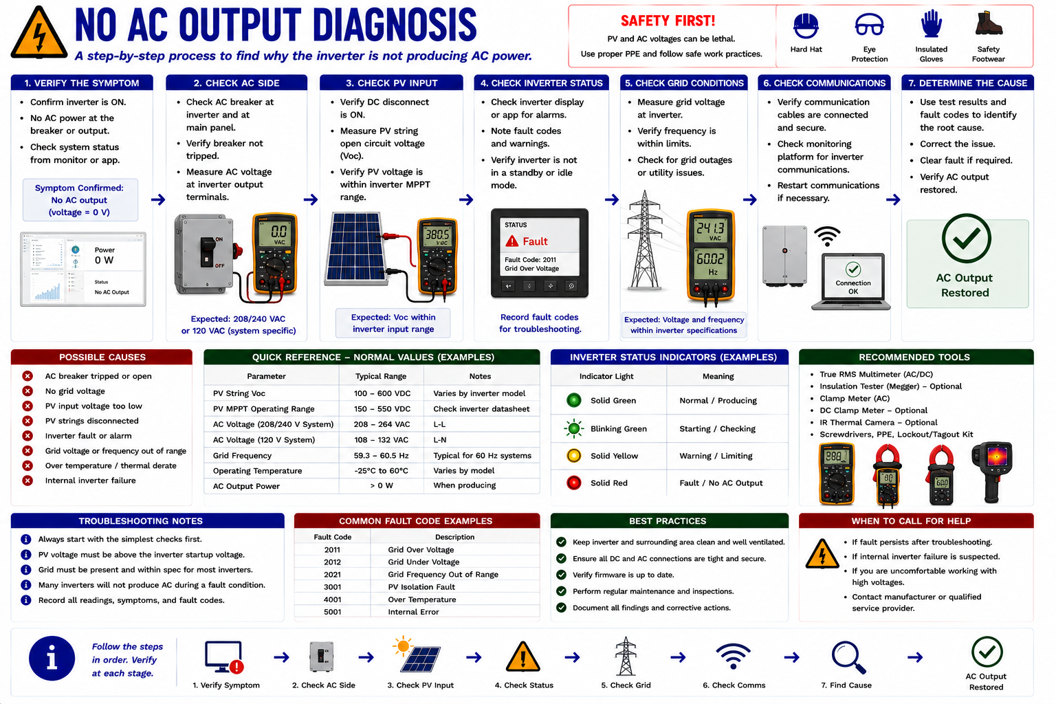
Does the Inverter Have Acceptable Grid Power?
Verify the AC conditions established in Lesson 12. Confirm that expected utility voltage reaches the PV circuit, AC disconnect, and inverter.
If acceptable AC voltage is missing, remain on the AC side of the system. Investigate the utility supply, breaker, disconnect, fuses where applicable, wiring, connections, and other equipment between the last normal test point and the first abnormal one.
Does the Inverter Have PV Input?
If acceptable grid voltage is present but the inverter does not produce AC power, verify the DC input as developed in Lesson 13.
If expected DC voltage or current is missing, move upstream toward the associated strings rather than condemning the inverter.
Is the System Being Intentionally Prevented From Operating?
Check rapid shutdown, external controls, communications requirements, battery or hybrid operating modes, utility controls, inverter startup delays, protective states, and other system-specific conditions.
An inverter that refuses to operate because a required condition is missing may be functioning exactly as designed.
Separate Environmental Conditions From Electrical Faults
Low production requires a different diagnostic approach from complete loss of output. The system is operating, so the technician must determine whether the output is reasonable for current conditions and, if not, which portion of the system is responsible.
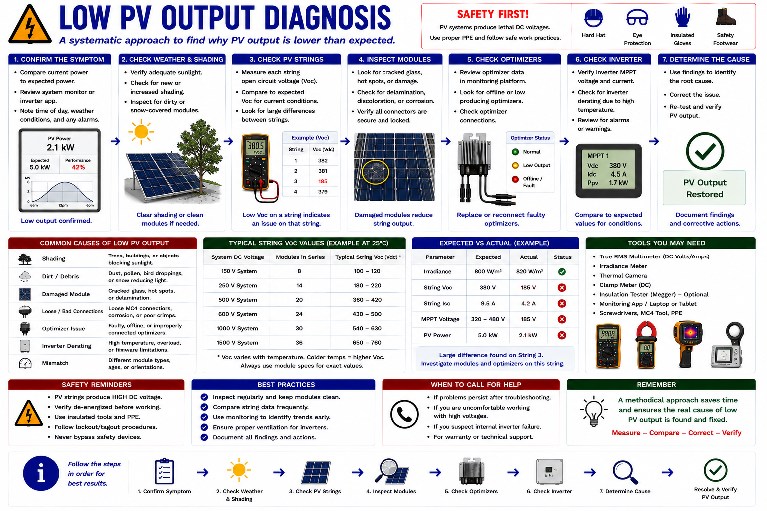
Is the System Actually Underperforming?
Weather
Clouds, haze, smoke, snow, and changing irradiance directly affect available PV power.
Time and Season
Sun angle and available solar hours change throughout the day and year.
Shading
Trees, buildings, vegetation, new construction, antennas, equipment, and debris can change array shading over time.
Module Temperature
Hot modules generally operate at lower voltage than cooler modules.
Soiling
Heavy dirt, dust, leaves, bird contamination, or other material can reduce available irradiance at the module surface.
System Limitation
Inverter clipping, curtailment, battery charging, export limits, or other operating controls may intentionally limit output.
Compare Major Sections of the Array
If environmental conditions do not explain the low production, compare inverter inputs, MPPT channels, strings, or module-level production as the system architecture permits.
The goal is to determine whether the reduction affects the entire system or only one portion of the array.
System-Wide Symptoms and Localized Symptoms Point in Different Directions
If every string or inverter input is similarly low, look for something common to the entire system. If one string is abnormal while comparable strings operate normally, concentrate the investigation on that string.
Use the Other Strings as References
Comparable strings provide some of the most useful diagnostic information available in a PV array. Under similar sunlight and temperature conditions, strings with the same module count and orientation should normally produce reasonably similar electrical results.
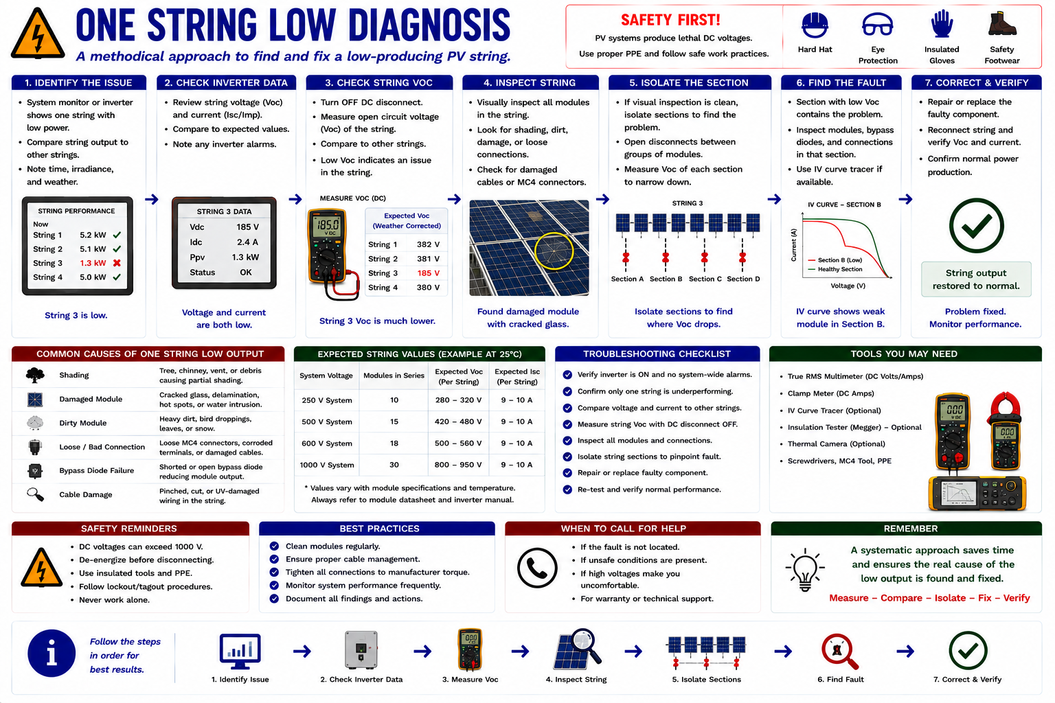
Compare Expected and Measured String Voltage
If one string has substantially lower voltage than comparable strings, review its module count, connections, polarity, wiring, fuses, module condition, rapid-shutdown equipment, and other components unique to that circuit.
Use the expected-versus-measured voltage process developed in Lesson 13 rather than judging the reading without a reference.
Normal Voltage With Low Current Requires a Different Diagnosis
A string may show reasonable open-circuit or operating voltage while producing less current than comparable strings. Consider shading, soiling, damaged modules, high-resistance connections, bypass behavior, module-level electronics, and other conditions that reduce loaded performance.
This is why a voltage measurement alone cannot establish that a PV string is healthy.
Find the Break in the Series Circuit
If testing indicates an open string, work through accessible test points in a controlled direction. Look for open fuses, damaged conductors, disconnected or improperly engaged connectors, failed terminations, module-level equipment, and other interruptions in the series path.
Use the last known-good electrical point and the first abnormal point to narrow the physical area requiring inspection.
Go to Individual Modules Only After the String Points You There
Once a particular string or array section has been identified, module-level testing can be used to isolate the remaining problem.
Apply the techniques from Lesson 14: compare module Voc, use appropriate PV test equipment where necessary, inspect connectors and wiring, evaluate optimizer input and output behavior, and compare suspect equipment with known-good neighboring equipment.
Use Monitoring to Narrow the Array Before Roof-Level Testing
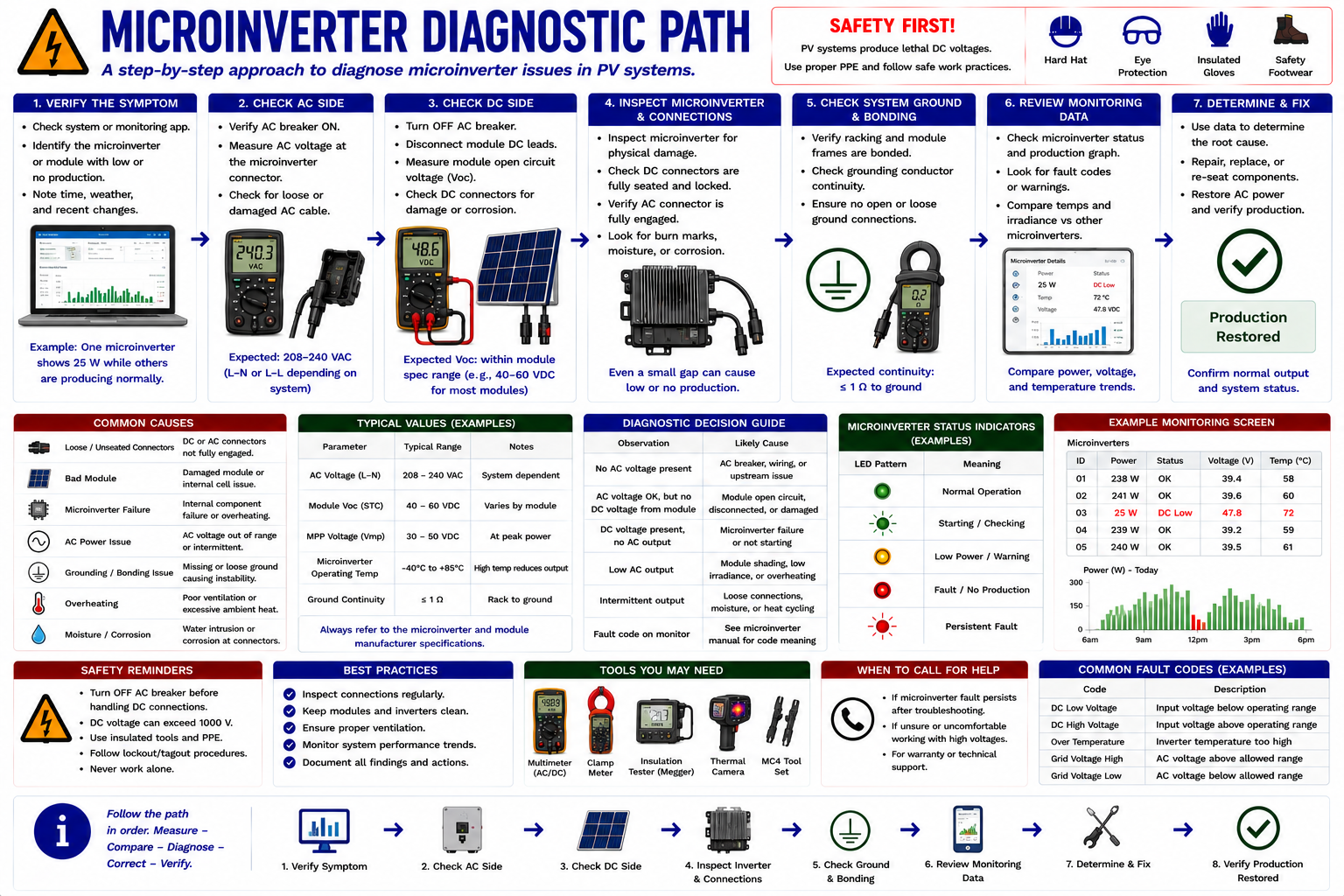
Microinverter systems require a different path because DC-to-AC conversion occurs at each module. There is no conventional high-voltage DC string running to a central inverter.
Begin with system monitoring, AC branch circuits, communications, and the individual microinverter status available through the installed platform.
Separate Communications From Production
A missing device in the monitoring system may indicate a communications problem, a loss of AC branch power, a module problem, a microinverter fault, or another equipment-specific condition.
Determine whether the device is actually not producing or whether its production information simply is not reaching the monitoring system.
Look for What the Devices Share
If several microinverters disappear or stop producing simultaneously, investigate common branch-circuit equipment, breakers, wiring, communications equipment, gateway operation, utility conditions, and other shared components before assuming multiple microinverters failed together.
Use History, Conditions, and Patterns
Intermittent faults can be more difficult to diagnose because the system may operate normally while the technician is present. Review event history and monitoring trends and look for relationships between the fault and temperature, irradiance, rain, wind, time of day, output level, or other conditions.
Loose connections, damaged conductors, overheating, moisture intrusion, grid-voltage problems, communications issues, and protective operation can all produce intermittent symptoms.
Use Temperature as Evidence, Not as the Diagnosis
Thermal imaging can help identify abnormal heating in modules, connectors, conductors, disconnects, breakers, fuses, and terminations. However, an elevated temperature does not by itself identify the underlying cause.
Verify thermal findings with visual inspection, electrical measurements, loading conditions, environmental information, and comparison with similar equipment.
Translate the Code Into a Test
A fault code should guide the diagnostic process rather than replace it. Determine what condition causes the code, identify the electrical or operating values associated with that condition, and test those values.
Example: A grid-voltage fault tells the technician to investigate grid voltage and the AC path. It does not automatically prove that the inverter’s voltage-sensing circuitry has failed.
Replacement Is Not a Diagnostic Test
Replacing an inverter, module, optimizer, breaker, or other component merely to see whether the problem disappears can be expensive and can introduce additional problems.
Whenever practical, establish the failed condition through measurements, comparisons, inspection findings, monitoring data, manufacturer diagnostics, or another repeatable test before replacing the component.
Ask Why the Reading Is Abnormal
Finding an abnormal measurement is an important step, but it is not necessarily the end of the diagnosis.
Missing Voltage
What opened, disconnected, shut down, or otherwise interrupted the circuit?
Low Voltage
Is the condition caused by configuration, temperature, missing modules, module-level electronics, wiring, or another electrical problem?
Low Current
Is irradiance low, is the circuit shaded, or is resistance or component performance limiting current?
Overheating
Is the heat caused by high resistance, excessive current, poor contact, equipment failure, or normal operating conditions?
Use More Than One Piece of Evidence When Possible
A strong diagnosis is supported by multiple observations that point toward the same cause.
For example, a low-current string combined with a thermal anomaly, visibly damaged connector, and abnormal voltage drop at the same location provides much stronger evidence than any one observation alone.
Record the Original Condition
Before changing the system, document the measurements and observations that established the diagnosis. Record fault codes, inverter status, monitoring data, test locations, electrical measurements, weather conditions, and photographs where useful.
This creates a baseline that can be compared with the system after repair.
Repeat the Test That Identified the Fault
The best verification is often to repeat the same measurement or observation that originally demonstrated the problem.
If a string was low, measure it again. If an inverter had no AC output, verify output current. If a module was missing from monitoring, verify that it has returned. If a connector was overheating, confirm normal operation after the repair under suitable loading conditions.
Repair verification: Do not assume that replacing a suspected component proves the diagnosis. Verify that the original abnormal condition is gone.
A Repeatable PV Diagnostic Process
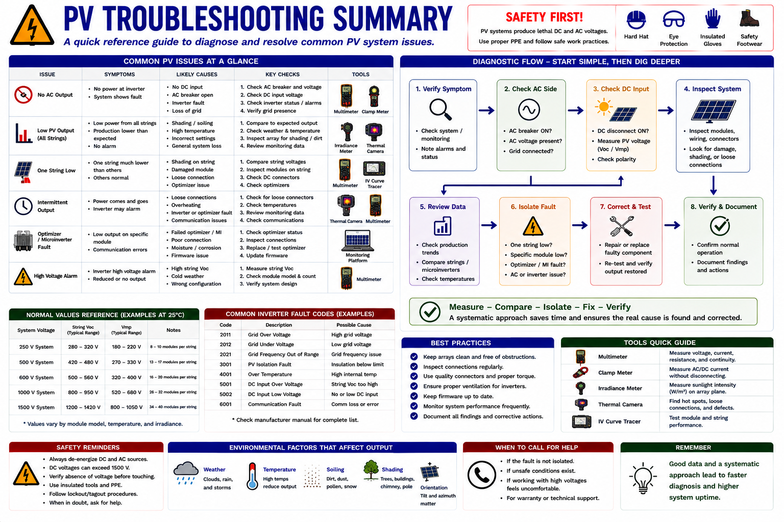
Use the Same Logic on Every Service Call
Define and Verify the Complaint
Know exactly what is wrong before beginning the diagnosis.
Review System Information
Check documentation, equipment configuration, monitoring, fault history, and expected operating conditions.
Inspect the System
Identify visible, thermal, environmental, and mechanical abnormalities before electrical testing.
Verify the AC Side
Determine whether acceptable grid power reaches the inverter and whether AC output is present.
Verify the DC Side
Determine whether reasonable PV voltage and current reach the string inverter.
Compare Strings or Branches
Use similar circuits to identify which portion of the array is abnormal.
Move to Module Level
Test modules, optimizers, or microinverters only after the broader circuit has localized the problem.
Identify the Root Cause
Determine why the abnormal condition exists before replacing components.
Repair and Restore
Correct the fault and return the system to service using the approved procedure.
Verify and Document
Repeat the critical measurements, confirm normal operation, and document the completed service.
Troubleshooting Often Requires Measurements Around Energized Equipment
PV systems can contain multiple simultaneous energy sources, including utility AC, illuminated PV modules, and battery storage where installed. Opening one disconnect does not necessarily remove every electrical source.
Electrical diagnosis should be performed only by qualified personnel using appropriately rated meters, leads, clamps, PPE, safe-work procedures, and manufacturer instructions. Identify the energy sources and determine the electrical condition of the equipment before beginning work.
What You Should Take From This Lesson
Start With the Symptom
Define and verify the actual complaint before testing components.
Work From Broad to Specific
Inspect the complete system and verify AC and DC conditions before moving to individual modules or devices.
Use Comparisons
Comparable strings, inverter inputs, branches, and neighboring modules provide valuable diagnostic references.
Look for Common Causes
Multiple simultaneous symptoms often indicate a shared electrical, environmental, control, or communications problem.
Do Not Confuse the Reporter With the Cause
An inverter or monitoring system may identify a condition caused by equipment somewhere else in the system.
Do Not Swap Parts as a First Test
Establish evidence that a component has failed before replacing it whenever practical.
Verify the Repair
Repeat the test that demonstrated the original fault and confirm that the complete system has returned to expected operation.
Electrical Testing and Troubleshooting
You have now progressed from preparing for electrical measurements through AC testing, DC string testing, module and optimizer testing, and finally complete systematic PV system diagnosis.
Part IV moves from diagnosis into corrective work: repair planning, component replacement, connector and conductor repair, inverter and module replacement, system restoration, and service documentation.
Continue to Part IV — Repair, Replacement, and Documentation →
Electrical Testing and Troubleshooting
Return to the Part III landing page to review Lessons 11 through 15.