Planning a Systematic Solar Inspection
Effective PV troubleshooting begins before the first electrical measurement is taken. A technician should first determine what type of system is installed, identify the major components, understand the expected power path, document equipment information, and perform a systematic visual inspection.
This lesson establishes a repeatable inspection process that begins at the utility and building electrical system, follows the PV equipment toward the array, and records the information needed for later electrical testing. The goal is to understand the system before attempting to diagnose it.
Inspect First — Measure Later
When a PV system has a production complaint, fault indication, intermittent problem, or unexplained shutdown, it can be tempting to immediately open equipment and begin taking electrical measurements. That approach can waste time and can expose the technician to hazards that have not yet been identified.
A better approach is systematic. Begin by identifying the installation, determining how power should move through it, reviewing available system information, and inspecting accessible equipment before beginning electrical testing.
Visual inspection often reveals conditions that explain the reported problem or substantially narrow the electrical tests that will be required.

Begin With the Information Already Available
Whenever possible, review available information before beginning the physical inspection. Even limited documentation can help the technician understand the system architecture and know what equipment should be present.
Reported Complaint
Determine what the owner or operator has actually observed. Examples include low production, no production, an inverter fault, intermittent operation, one missing module, or unexplained utility usage.
Monitoring Information
Review available production history, alarms, device status, communications information, and the time the reported condition began.
System Documentation
Look for installation drawings, equipment lists, previous service reports, permits, labels, photographs, commissioning records, and manufacturer information.
Previous Repairs
Determine whether modules, inverters, optimizers, microinverters, disconnects, connectors, roofing, or other equipment have previously been replaced or serviced.
Know What Problem You Are Trying to Verify
A statement such as “the solar isn’t working right” is not yet a useful technical description. The technician should establish what changed and how the problem was discovered.
What Is the Reported Condition?
Determine whether the complaint involves no production, reduced production, intermittent operation, an alarm, a communications problem, visible damage, or another specific condition.
When Did It Begin?
Determine whether the problem appeared suddenly or developed gradually over time.
Is It Continuous or Intermittent?
Ask whether the condition is always present or appears only at certain times of day, during certain weather, or under particular operating conditions.
What Changed?
Look for recent storms, roof work, electrical work, equipment replacement, utility changes, landscaping, construction, or other events that may be related.
Do Not Diagnose the Customer’s Description
A customer complaint is the starting point for the investigation, not the diagnosis. “Low production” may be caused by a PV fault, weather, seasonal conditions, increased building loads, monitoring problems, utility billing changes, shading, or another condition.
Record the complaint accurately, then use system evidence to determine what is actually occurring.
Determine What Type of PV Installation You Are Inspecting
Before selecting test points, determine the basic architecture of the system. Part I established that string inverters, microinverters, and optimizer-equipped systems have different electrical paths and different useful troubleshooting points.
Do not assume the system architecture from one visible component. A central inverter may indicate a conventional string system or an optimizer-based system. Equipment mounted beneath the modules may not be visible from ground level.
String Inverter
Look for DC strings from the array feeding centralized DC-to-AC conversion equipment.
Microinverters
Look for module-level DC-to-AC conversion and an AC collection circuit leaving the array.
Power Optimizers
Look for module-level DC electronics combined with DC strings feeding a compatible centralized inverter.
Battery Equipment
Identify whether energy storage is present. Batteries introduce another energy source and can substantially change shutdown, isolation, and troubleshooting procedures.
Follow the System in a Consistent Order
A consistent inspection path reduces the chance of overlooking equipment. One useful approach is to begin with the utility service and building distribution equipment and then work toward the PV array.
This direction also helps establish how PV power connects to the existing electrical system before following the circuit back toward its generating source.
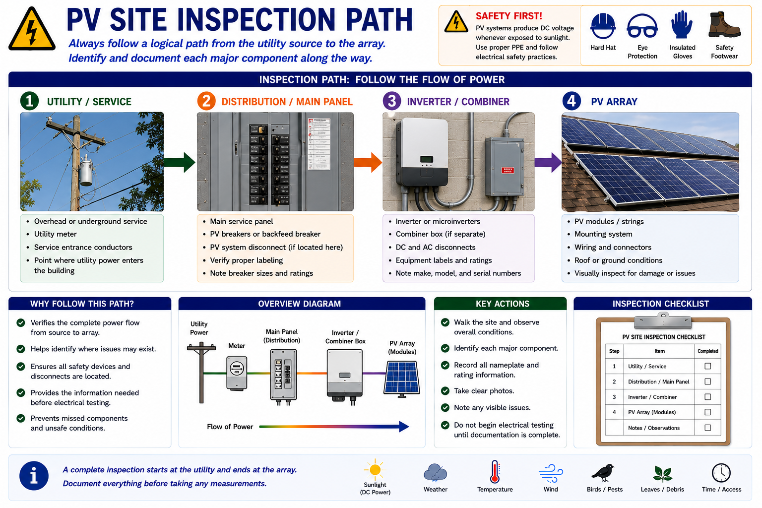
Start Where the PV System Meets the Building Electrical System
Identify the utility service, meter, service equipment, and any PV-related equipment located nearby. Look for labels identifying photovoltaic power sources, disconnects, rapid-shutdown controls, battery equipment, or other alternate energy sources.
At this stage the technician is primarily identifying and documenting equipment. Electrical measurements come later when the system and safe test points are understood.
Look for: utility meter arrangement, service equipment, PV labels, disconnect locations, battery or generator markings, physical damage, corrosion, open covers, missing hardware, and signs of previous electrical work.
Find the PV Connection to the Electrical System
Identify where the PV system connects to the building electrical distribution system. This may involve a dedicated PV breaker or another approved interconnection arrangement.
Record the breaker or disconnect identification, ratings, panel information, labeling, and any other equipment associated with the PV connection.
Also note whether the equipment condition matches the documentation and labels. Field modifications may have changed the installation since the original system was commissioned.
Identify the Power-Conversion and Collection Equipment
Locate the inverter or other power-conversion equipment. On a conventional string system, identify the DC inputs and AC output. On an optimizer system, identify the compatible central inverter and any related communications equipment. On a microinverter system, identify the AC collection, gateway, or combiner equipment associated with the array.
Record visible operating indicators and displayed faults without immediately resetting or power-cycling the equipment. An active fault may provide valuable evidence that disappears after a reset.
Preserve evidence: Photograph or record fault codes, warning indicators, display messages, breaker positions, disconnect positions, and equipment status before changing anything.
Inspect the Wiring Path
Follow accessible PV conductors and raceways toward the array. Note junction boxes, disconnects, combiner boxes, transitions, exposed conductors, conduit routing, supports, and areas where the wiring is exposed to weather or physical damage.
The detailed inspection of conductors, connectors, disconnects, inverters, and combiner equipment is covered in Lesson 9. At this stage, the goal is to establish where the circuits go and identify obvious conditions that affect the inspection plan.
Finish by Inspecting the Generating Equipment
Identify the number and location of array sections and note their orientation, tilt, access conditions, shading, and obvious physical condition.
Determine whether the modules appear consistent with available documentation. Look for evidence of replacements, different module types, missing modules, added equipment, roof work, or other modifications.
Lesson 8 develops the detailed inspection process for modules and mounting systems.
Document the Equipment Before Troubleshooting It
Equipment identification is more than writing down a manufacturer name. Model numbers, serial numbers, electrical ratings, circuit configuration, firmware or operating information when available, and physical equipment locations can all become important during troubleshooting.
Good documentation also allows the technician to obtain the correct manufacturer service information instead of relying on procedures intended for similar-looking but different equipment.
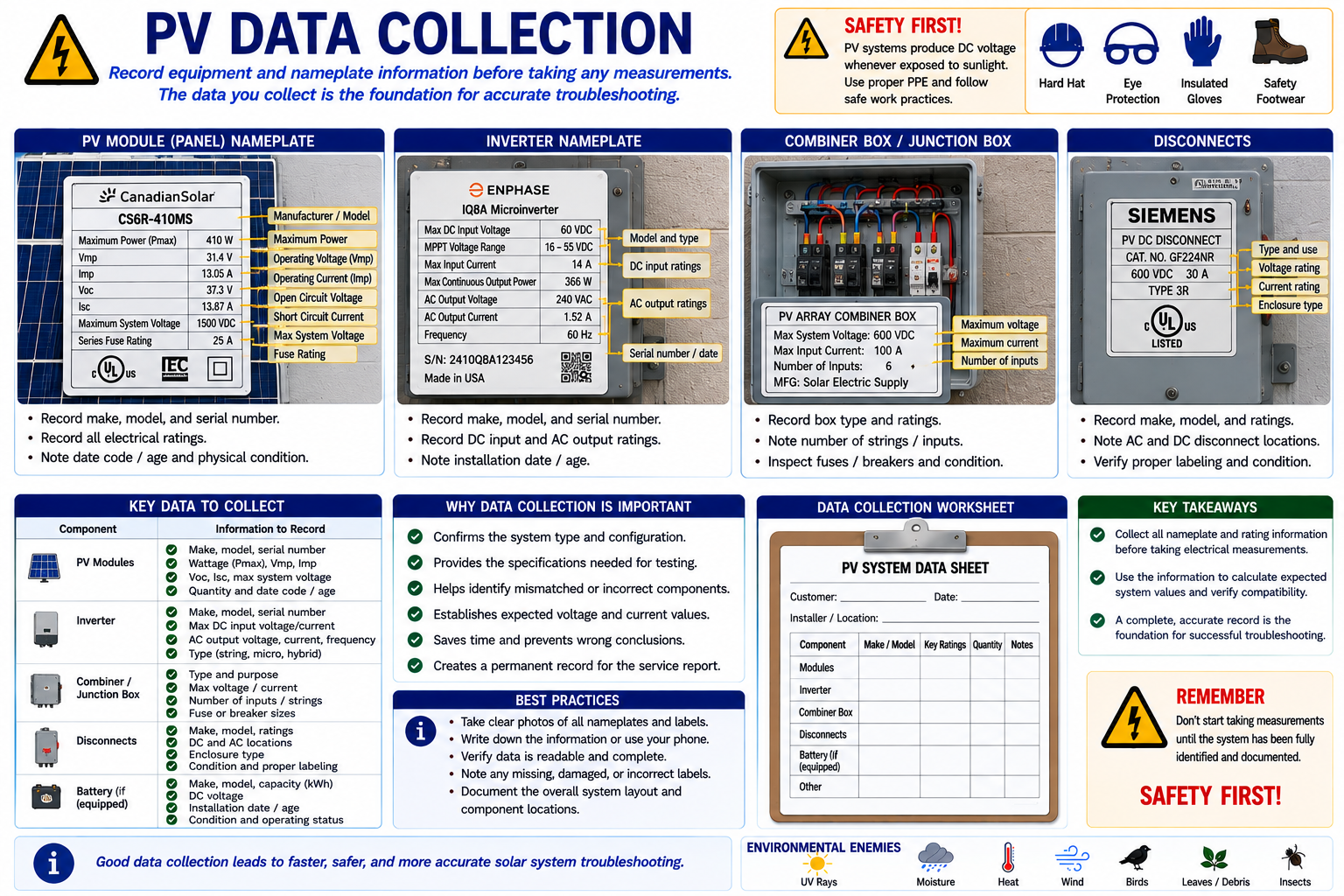
Create a Useful System Record
PV Modules
Manufacturer, model, rated power, Voc, Vmp, Isc, Imp, quantity, and any visibly different replacement modules.
Inverters
Manufacturer, model, serial number, DC input ratings, AC output ratings, displayed status, active fault codes, and communications condition.
MLPE
Identify optimizer or microinverter manufacturer and model information where available, along with module-level monitoring information.
Strings
Record available string identification, module count, inverter input assignment, array section, and other information needed to compare similar circuits.
Disconnects and Combiners
Record ratings, circuit identification, fuse or breaker information where applicable, and the equipment served.
Distribution Equipment
Identify the PV interconnection point, breaker or disconnect ratings, panel information, and available utility or service information.
Photograph Before You Disturb the System
Photographs provide a record of the original condition and can capture information that is difficult to reconstruct later. Take photographs before opening, disconnecting, moving, cleaning, resetting, or repairing equipment.
Overall Equipment
Photograph enough surrounding area to show where the equipment is located and how it relates to nearby components.
Nameplates
Take clear photographs that allow manufacturer, model, serial number, and electrical ratings to be read later.
Fault Displays
Record inverter displays, indicators, monitoring messages, and fault codes before attempting a reset.
Visible Defects
Photograph damaged modules, conductors, connectors, enclosures, mounting components, corrosion, overheating, water intrusion, and other abnormal conditions.
Do Not Reset the Evidence Away
One of the easiest troubleshooting mistakes is immediately resetting an inverter, cycling a disconnect, clearing an alarm, or restarting communications equipment.
A reset may temporarily restore operation while also removing the conditions needed to understand why the system stopped. Record the system state, fault information, operating indicators, and relevant monitoring data before intentionally changing its condition unless safety requires immediate shutdown.
The Installed System May No Longer Match the Original Design
PV installations can change over years of service. Modules may have been replaced. An inverter may have been upgraded. Roofing work may have required array removal and reinstallation. Disconnects, breakers, communications equipment, or wiring may have been changed.
Use existing drawings and documentation as useful references, but verify the actual installed equipment. The technician must troubleshoot the system that exists today, not only the system shown on an older drawing.
Record Conditions That Can Affect the Inspection
Weather and site conditions can affect both PV operation and the safety of the inspection. Record conditions that may influence production measurements or physical access.
Sunlight
Record whether the array is in strong direct sunlight, partial cloud, heavy cloud, or shade.
Temperature
Ambient and module temperatures can affect electrical characteristics and equipment operation.
Wind
Wind can create significant hazards during roof access and may make some inspection work inappropriate.
Wet Conditions
Rain, snow, ice, condensation, or wet roofing can change both electrical and fall hazards.
Shading
Record current shading and identify trees, buildings, vents, chimneys, vegetation, or other objects that can affect array exposure.
Recent Weather
Storms, hail, high winds, lightning, flooding, snow, or extreme heat may be directly related to the reported problem.
Decide Whether the Inspection Can Continue Safely
A visual inspection is also a safety assessment. Before opening equipment or accessing an array, determine whether site conditions permit the work to continue safely.
Stop and reassess when conditions include damaged electrical equipment, exposed conductors, evidence of arcing or fire, unstable mounting, structural damage, unsafe roof conditions, flooding, severe corrosion, animal activity, or other hazards outside the planned scope of work.
Inspection does not mean contact. Many important conditions can be identified visually without touching, opening, disconnecting, or energizing equipment.
Remember That the Array Is an Energy Source
Illuminated PV modules can produce DC voltage even when an inverter is shut down or a disconnect is open. Utility-connected equipment can also remain energized from the AC side, and battery systems introduce stored electrical energy that does not depend on sunlight.
Do not assume a system is de-energized based on switch position alone. Identify all energy sources, understand the equipment architecture, follow manufacturer procedures and applicable electrical safe-work requirements, use required PPE, and verify electrical conditions with properly rated test equipment before contact.
Testing Comes After the System Has Been Defined
Electrical testing should answer a specific question. Once the inspection has established the system architecture, equipment configuration, complaint, visible condition, and likely fault area, the technician can select measurements that meaningfully narrow the diagnosis.
This is more efficient than collecting random voltage and current readings throughout the installation and attempting to determine their significance afterward.
Identify
Determine what equipment and system architecture are installed.
Document
Record ratings, configuration, operating state, faults, environmental conditions, and available monitoring information.
Inspect
Look for physical conditions that explain the complaint or change the troubleshooting plan.
Form a Question
Decide what the next measurement needs to prove or eliminate.
Test
Take the appropriate electrical measurement under known conditions and compare the result with the expected value.
Every Test Should Have a Reason
Before connecting a meter, the technician should be able to answer three questions: What am I measuring? What value or condition do I expect? What will the result tell me?
If those questions cannot be answered, more inspection or system identification may be needed before the measurement is useful.
What You Should Take From This Lesson
Define the Complaint
Determine what was observed, when it began, whether it is continuous or intermittent, and what may have changed.
Identify the System Architecture
Determine whether the installation uses string inverters, microinverters, optimizers, batteries, or another configuration before choosing test points.
Follow a Consistent Inspection Path
Trace the system from utility and service equipment through distribution and PV equipment toward the array.
Document Before Changing Anything
Record equipment information, fault codes, operating state, photographs, monitoring data, and environmental conditions before resetting or disturbing equipment.
Look Before You Measure
Visual inspection may identify the fault or substantially narrow the electrical tests that are actually necessary.
Make Every Measurement Purposeful
Know what you expect to measure and how the result will change the diagnostic path before connecting the test instrument.
Inspecting PV Modules and Mounting Systems
The next lesson moves the inspection to the array itself. It examines normal and damaged PV modules, common physical damage, mounting-system conditions, and inspection points for both roof-mounted and ground-mounted arrays.
Visual Inspection and Assessment
Return to the Part II landing page for all four Visual Inspection and Assessment lessons.