PV System Components and Power Flow
A PV system is easier to troubleshoot when the technician can identify each major component and trace the electrical path from the solar modules to the building electrical system. Each component has a specific purpose, and each transition in the power path creates a logical place to inspect, measure, or isolate a problem.
This lesson follows typical string-inverter and microinverter installations from the array through the associated DC or AC equipment, distribution panel, building loads, and utility interconnection. The objective is not to design the system. The objective is to know what equipment should be present, what form of electrical power should be present at each point, and where the technician can begin narrowing a fault later in the course.
Learn the Electrical Path Before Testing It
A technician approaching an unfamiliar solar installation should be able to identify the major components and follow the expected power path through the system. In a conventional string-inverter installation, that path begins as DC at the modules and strings, remains DC through the array wiring and associated DC equipment, changes to AC at the inverter, and then continues through the building electrical system.
A microinverter system moves the DC-to-AC conversion point to the array. The same field principle still applies: identify each component in order and determine what type of electrical power should be present on each side of it.
The Electrical Source Begins at the Modules
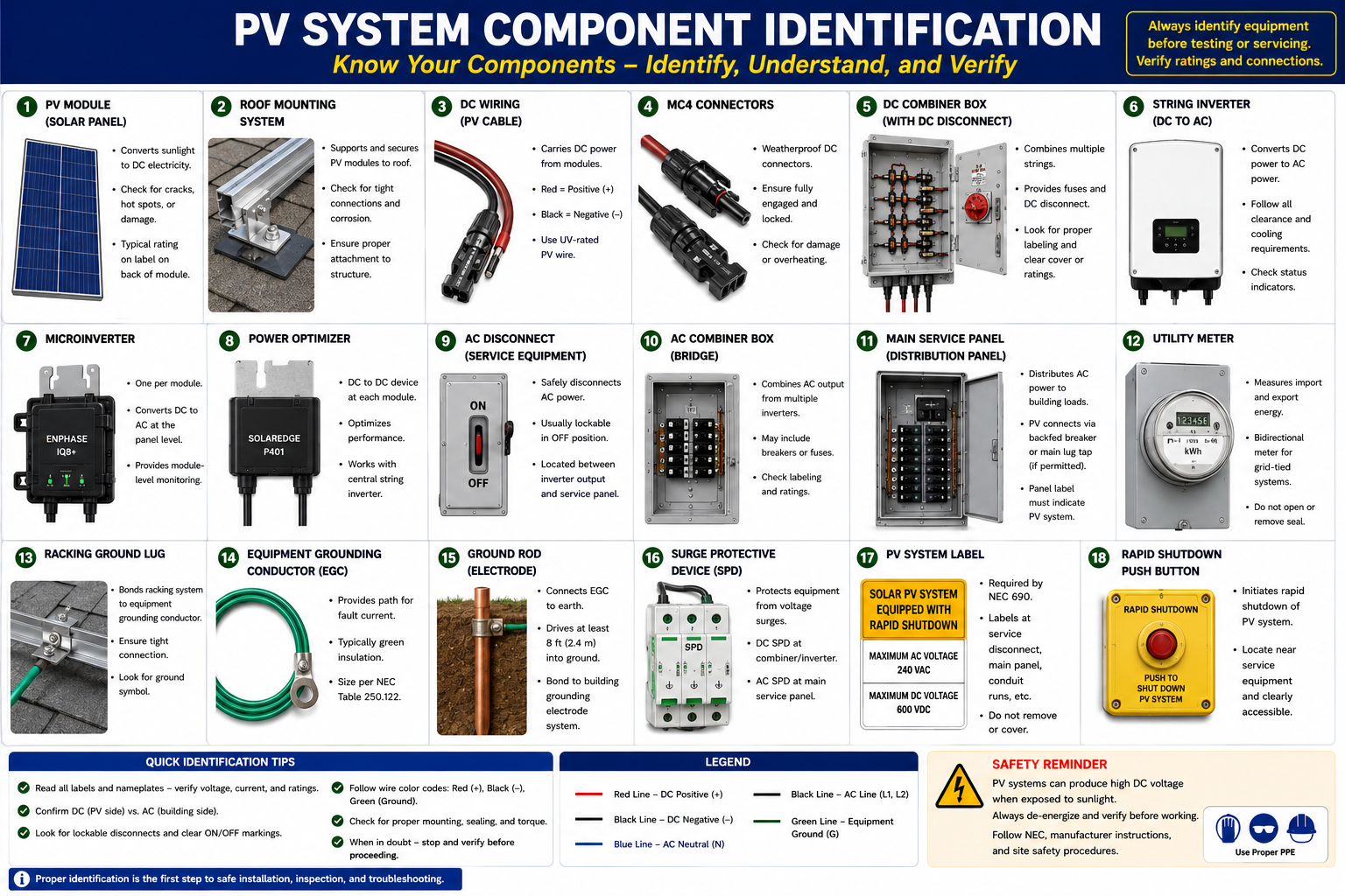
Photovoltaic modules are the generating source. When sufficient light reaches the cells, the modules produce DC electrical power. In a conventional string-inverter system, multiple modules are connected in series to form strings as discussed in Lesson 3.
The array includes more than the modules themselves. Conductors, connectors, junction equipment, mounting and bonding components, and sometimes module-level power electronics are all part of the equipment the technician may encounter at the array.
PV Modules
Convert solar radiation into DC electrical power and provide the basic voltage, current, and power ratings used to evaluate system operation.
Module Conductors
Carry DC power between modules or between modules and module-level power electronics.
PV Connectors
Provide weather-resistant electrical connections between modules, strings, optimizers, microinverters, and related equipment.
Mounting and Bonding
Secure the modules mechanically while applicable grounding and bonding components provide the intended electrical fault path.
DC Travels From the Array to a Central Inverter
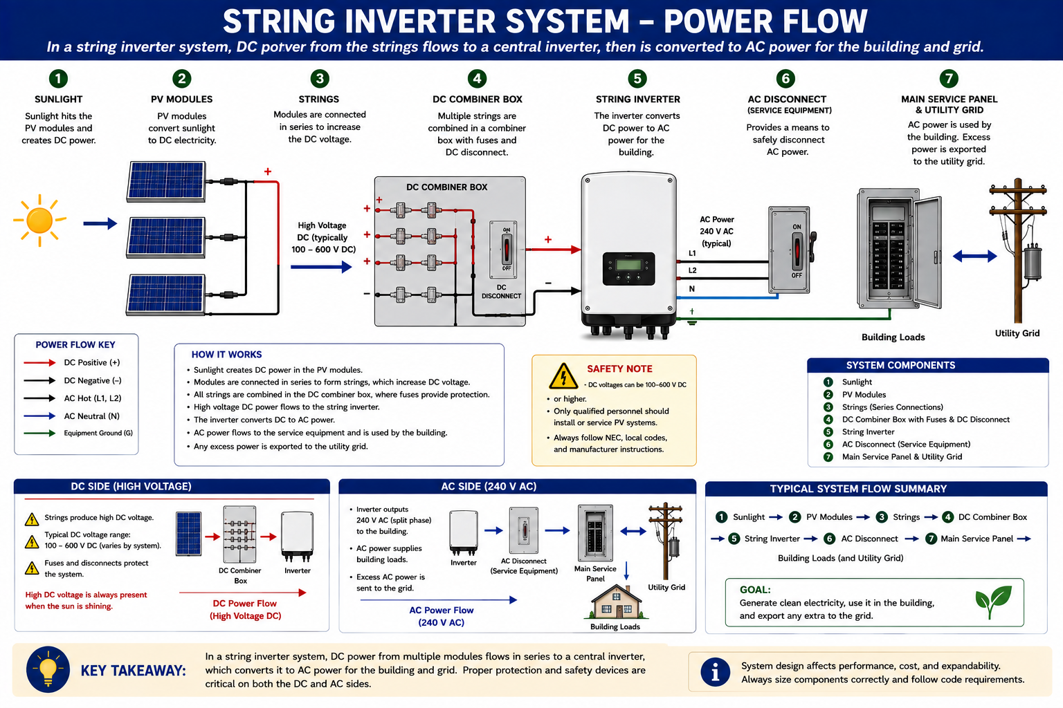
In a conventional string-inverter system, the modules form DC strings. Those strings carry power away from the array through conductors and any applicable combining, protection, junction, or disconnecting equipment before reaching the inverter.
The inverter becomes the primary boundary between the DC and AC portions of the system. This makes it one of the most useful locations for troubleshooting because the technician can determine whether appropriate DC power is arriving and whether corresponding AC power is leaving.
Modules Generate DC Power
Solar radiation reaching the PV modules produces DC voltage and current.
Modules Form Strings
Series-connected modules create the higher DC voltage required by the string-inverter system.
DC Power Moves Toward the Inverter
String conductors carry power through the applicable junction, combining, protective, and disconnecting equipment.
The Inverter Converts DC to AC
The central inverter converts the PV-generated DC electricity into AC electricity compatible with the building electrical system.
AC Power Enters the Building System
The inverter output passes through the applicable AC equipment and connects to the building electrical distribution system.
Follow the DC Circuit Toward the Inverter
The positive and negative conductors from a PV string carry DC power away from the array. Depending on the installation, those conductors may run directly to an inverter or first pass through a junction box, combiner box, disconnect, or other equipment.
For troubleshooting, this creates useful points where the circuit can sometimes be divided into smaller sections. If voltage is present at one point but missing at another, the technician has narrowed the possible fault to the equipment and wiring between those locations.
Field point: Follow the actual conductor routing instead of assuming where a string goes. Adjacent groups of modules may feed different inverter inputs or entirely different inverters.
Multiple Strings May Be Collected and Isolated
A DC combiner box provides a location where multiple PV source circuits can be brought together before a larger combined DC circuit continues toward the inverter. Depending on the installation, this equipment may also contain fuses, terminals, surge protection, monitoring equipment, or other protective components.
PV systems may also contain DC disconnecting means that allow portions of the circuit to be opened for operation or service. The exact arrangement varies considerably between systems.
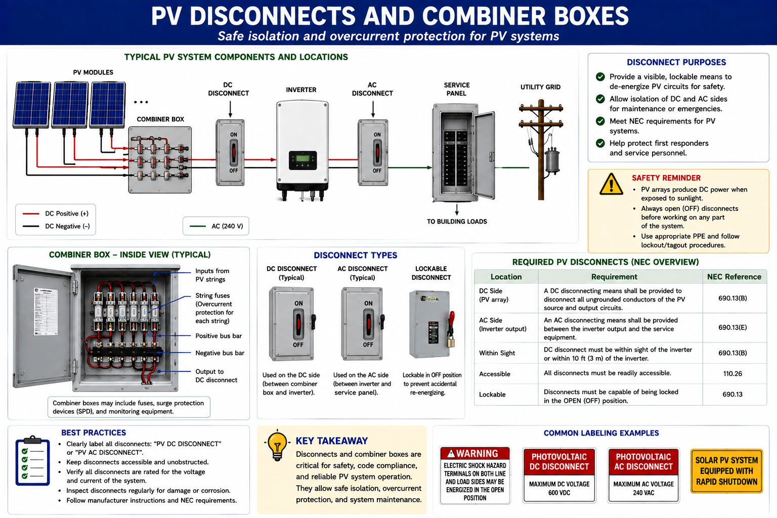
String Inputs
Individual PV strings enter the combiner or compatible inverter input equipment.
Protective Devices
Where required, fuses, breakers, surge devices, or other components protect associated circuits and equipment.
Disconnecting Means
Disconnect equipment allows an electrical path to be opened at a defined location but does not necessarily remove every source of voltage from the equipment.
Inspection and Test Point
Accessible equipment can provide locations for identifying strings, inspecting connections, checking protective devices, and making later electrical measurements.
A DC Disconnect Does Not Turn Off the PV Modules
Opening a DC disconnect interrupts the electrical circuit at that location, but illuminated PV modules can continue generating voltage on the source side of the open device.
The technician must determine which side of the disconnect can remain energized and follow manufacturer procedures and applicable safe-work requirements before opening or testing equipment.
The Central DC-to-AC Boundary
The string inverter receives DC input from one or more PV strings and converts that energy into AC electricity. The inverter may also perform maximum-power-point tracking, monitoring, communications, protective functions, and utility-interconnection functions.
For service work, the inverter provides an important troubleshooting boundary. If appropriate DC input is present but AC output is not, the diagnostic path differs from a condition where the inverter receives no DC input at all.
DC Side
Evaluate whether expected string or array voltage is reaching the inverter inputs.
AC Side
Verify whether proper grid-side voltage is present and whether the inverter is delivering current into the AC system.
Status Information
Displays, indicators, fault codes, monitoring portals, and manufacturer diagnostic tools may provide additional evidence.
Operating Conditions
Sunlight, temperature, utility voltage, protective functions, system configuration, and equipment state all influence inverter operation.
The Conversion Point Moves to the Array
A microinverter system changes the electrical path because the DC-to-AC conversion occurs at or near the individual PV modules. The short DC connection is local to the module and microinverter, while the collection circuit carrying power away from the array is AC.
Multiple microinverter outputs are interconnected through compatible AC branch-circuit equipment before the power reaches downstream disconnecting, combining, and distribution equipment.
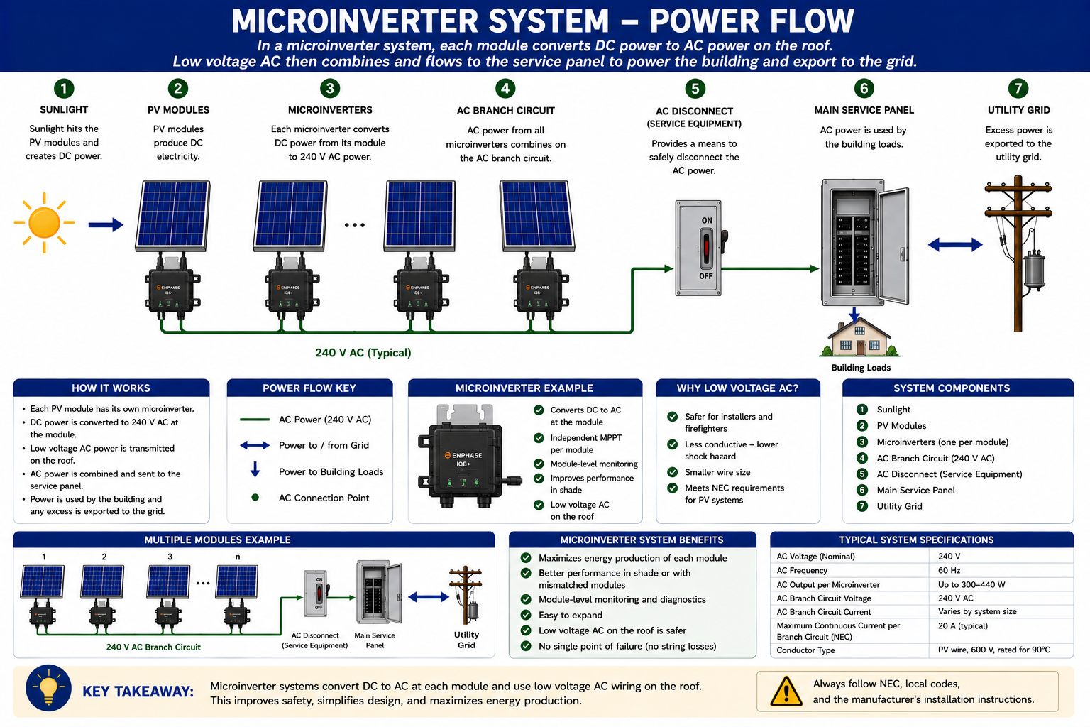
Troubleshooting consequence: A microinverter system does not have the same long DC string path used by a conventional central string inverter. Follow the AC collection circuit and use module-level monitoring or local module and microinverter testing when appropriate.
Microinverter Outputs Must Be Combined on the AC Side
The outputs from multiple microinverters are interconnected through compatible AC branch-circuit or collection equipment. Depending on the system, this may include rooftop junction equipment, an AC combiner, gateway equipment, disconnects, and downstream overcurrent protection.
The technician should identify where the individual microinverter branch circuits become a larger AC circuit and where useful electrical test points are available.
PV Power Joins the Building Electrical System
Once PV power has been converted to AC, it connects to the building electrical system through the approved interconnection arrangement. In many installations, this includes a dedicated PV breaker or another approved connection associated with the main electrical distribution equipment.
The distribution panel becomes an important troubleshooting reference because the technician can verify whether utility AC voltage is present and determine whether the PV system is delivering current into the building electrical system.
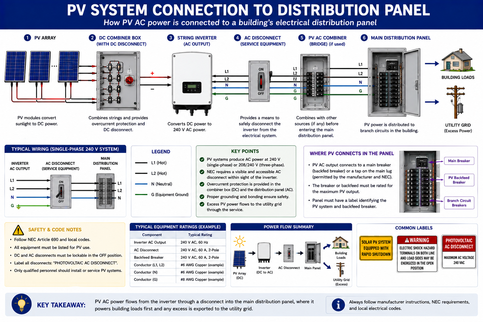
PV Production Serves Electrical Demand
When the PV system is operating and the building has electrical loads, locally generated solar energy can supply part or all of that demand. In a conventional grid-tied system, ordinary building loads are not normally divided into separate solar-only and utility-only circuits.
Instead, the PV source and utility interact through the building electrical system. If building demand is greater than PV production, the utility supplies the difference. If PV production exceeds building demand and export is permitted, excess power can flow toward the utility.
Production and Load at the Same Time
If the PV system is producing 6 kW while the building is using 4 kW, approximately 4 kW can serve the local load and the remaining production may flow toward the utility in an exporting system.
If the building is using 8 kW while the PV system produces 6 kW, PV production supplies part of the load and the utility provides the remainder.
A Grid-Tied PV System Operates in Parallel With the Utility
The utility remains another source of AC power for the building. During periods of insufficient solar production, power is imported from the utility. When solar production exceeds building demand and the system is permitted to export, power may flow from the customer electrical system toward the grid.
Utility metering and interconnection arrangements vary by location. For technician troubleshooting, the immediate concern is normally whether acceptable utility voltage is present and whether the PV equipment is interconnected and operating as intended.
Power Flow Tells You Where to Test Next
Once the component sequence is understood, troubleshooting becomes a process of determining how far through that sequence normal electrical conditions can be verified.
If utility voltage is normal but the PV system has no AC output, move toward the inverter or microinverter collection equipment. If a string inverter has no AC output and its expected DC input is also missing, move toward the DC strings. If appropriate DC input and grid-side AC conditions are both present but the inverter remains offline, inverter status, protection, communications, or equipment faults become more important.
Break the Installation Into Electrical Sections
Utility and Building AC
Verify that appropriate utility conditions exist and identify the PV connection to the building electrical distribution equipment.
PV AC Circuit
Follow the solar breaker, AC disconnect, inverter output, combiner, or microinverter collection circuit as applicable.
Power Conversion Equipment
Identify the string inverter, microinverters, optimizer system, hybrid equipment, or other power-conversion devices and review their operating status.
PV DC Circuits
On string-inverter systems, trace the DC path through inverter inputs, disconnects, combiner equipment, junctions, strings, and array wiring.
Module-Level Equipment
After the larger system has narrowed the fault, move toward individual modules, optimizers, microinverters, connectors, or local conductors as necessary.
Not Everything Carries the Main Power Path
PV installations contain additional equipment that may not appear directly in the primary power-flow path but remains important to safe, reliable operation and troubleshooting.
Grounding and Bonding
Provides the intended electrical fault-current and bonding paths for equipment, enclosures, module frames, and mounting components where applicable.
Surge Protection
Some installations include surge protective devices on the DC side, AC side, or both.
Rapid-Shutdown Equipment
Where installed, rapid-shutdown devices and controls alter the energized condition of portions of the PV system according to the system design.
Monitoring and Communications
Gateways, meters, current transformers, network equipment, and manufacturer monitoring systems can provide valuable diagnostic information even though they may not carry the primary PV power.
Use the Equipment Information
Do not rely only on appearance when identifying PV equipment. Read manufacturer labels and nameplates. Record model information, voltage and current ratings, AC or DC function, circuit identification, disconnect purpose, and other information that helps establish what is installed.
Correct identification also allows the technician to find the appropriate manufacturer documentation, shutdown procedures, fault information, and service instructions later in the troubleshooting process.
Energy Can Enter the System From More Than One Direction
A grid-connected PV system may have utility AC voltage available from one direction while illuminated modules produce DC energy from another. Battery-equipped systems introduce an additional stored-energy source.
Never assume that opening one disconnect removes every source of electrical energy. Identify the complete power path, determine which conductors may remain energized, follow manufacturer instructions and applicable safe-work requirements, and verify conditions with properly rated test equipment before contact.
What You Should Take From This Lesson
Start at the Source
PV modules generate DC electricity and are electrically organized into circuits that feed the rest of the solar installation.
Identify the DC Equipment
String wiring, connectors, junctions, combiner equipment, protective devices, and disconnecting means carry or control power between the array and central inverter in a string system.
Find the DC-to-AC Boundary
A string inverter creates that boundary at the central inverter, while a microinverter creates it at or near the individual PV module.
Follow AC to the Distribution System
Inverter or microinverter output passes through the appropriate AC equipment and connects to the building electrical distribution system.
Power Flow Guides Troubleshooting
Each component and connection provides another opportunity to determine where normal operation ends and the abnormal condition begins.
PV System Ratings, Production, and Aging
The final Part I lesson explains why actual PV production rarely equals the nameplate rating continuously. It examines module and system ratings, sunlight, temperature, daily and seasonal production, system losses, normal degradation, and the effect of age on expected performance.
PV Solar System Fundamentals
Return to the Part I landing page for all six PV Solar System Fundamentals lessons.