Refrigerant Recovery Equipment and Setup
Refrigerant recovery is not simply a matter of connecting a machine and turning it on. Safe and effective recovery depends on selecting equipment that is appropriate for the refrigerant, connecting the system correctly, using a suitable recovery cylinder, monitoring cylinder weight, and choosing a recovery method that matches the type and quantity of refrigerant in the appliance.
A technician must also understand the path refrigerant takes through the equipment. In a standard manifold recovery setup, refrigerant moves from the system through the appropriate manifold connections, out the center service hose to the recovery machine, and then from the recovery machine into the recovery cylinder. Special methods such as push-pull recovery use a different connection arrangement and must be set up according to the recovery-machine manufacturer’s instructions.
Learning Objectives
Identify Recovery Equipment
Recognize the recovery machine, recovery cylinder, manifold gauge set, hoses, scale, and other equipment used during refrigerant recovery.
Connect Recovery Equipment Correctly
Trace the refrigerant path from the system through the manifold and recovery machine into the recovery cylinder.
Select the Proper Recovery Method
Explain the differences between liquid recovery, vapor recovery, and push-pull liquid recovery.
Set Up Equipment Safely
Use proper cylinder weighing, refrigerant identification, equipment ratings, hose management, and A2L-compatible recovery equipment.
Recovery Requires Several Pieces of Equipment Working Together
A typical field recovery setup includes the refrigeration appliance, access connections, a manifold gauge set or another approved connection arrangement, service hoses, a recovery machine, a recovery cylinder, and a scale. The technician may also use valve-core removal tools, refrigerant identifiers, filter-driers, additional hoses, and other accessories depending on the appliance and recovery procedure.
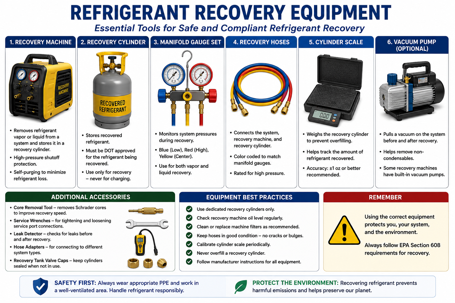
Recovery Machine
Moves refrigerant from the appliance into an external recovery cylinder and allows the technician to achieve the required recovery condition.
Recovery Cylinder
Provides a refillable pressure vessel designed for receiving recovered refrigerant.
Manifold Gauge Set
Provides controlled access to system high-side and low-side service connections and a center service port for connection to recovery or other service equipment.
Service Hoses
Carry refrigerant between the appliance, manifold, recovery machine, and recovery cylinder and must be suitable for the refrigerant and expected pressures.
Refrigerant Scale
Measures cylinder weight so the technician can determine how much refrigerant has entered the cylinder and avoid exceeding the allowable fill.
Additional Tools
Valve-core tools, filters, refrigerant identifiers, temperature instruments, and other accessories may improve recovery speed, protect equipment, or help prevent contamination.
Recovery Equipment Must Meet Applicable EPA Standards
EPA Section 608 regulations require refrigerant recovery and recycling equipment used for covered service work to meet applicable equipment-performance standards. Recovery equipment is tested to verify that it can achieve required recovery performance and limit refrigerant loss.
Modern recovery equipment normally carries a certification label identifying the testing organization and the category of appliance or refrigerant for which the equipment has been certified. The technician should use the machine within the applications and refrigerants specified by the manufacturer and certification.
Look at the Equipment Label
Do not assume that every recovery machine is approved for every refrigerant or application. Confirm the machine’s refrigerant compatibility, pressure rating, certification, operating instructions, and flammability suitability before connecting it to the system.
Know the Refrigerant Path Before Opening a Valve
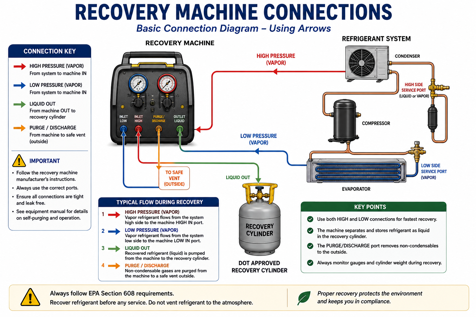
For a standard manifold gauge set, the blue hose and left manifold port connect to the low side, the red hose and right manifold port connect to the high side, and the yellow center hose is the service hose. During standard recovery, the yellow service hose connects the manifold to the inlet of the recovery machine.
The recovery machine outlet then connects through a separate hose to the recovery cylinder. Refrigerant therefore moves from the appliance, through the manifold, through the center service hose, into the recovery machine, and finally into the recovery cylinder.
The Scale Is Not Connected to the Refrigerant Circuit
The recovery cylinder physically sits on the scale. The scale measures weight only. No refrigerant hose connects to the scale display or passes through the scale.
Using Both Sides Can Improve Recovery
When the appliance and recovery procedure allow it, connecting to both the high side and low side can provide a larger flow path and can reduce recovery time. Liquid refrigerant is commonly removed through the high side while vapor is removed through the low side as the recovery progresses.
Access configuration varies among appliances. Some equipment has both high-side and low-side service ports, while other appliances may provide only one practical access point. Manufacturer service information and the recovery-machine instructions should guide the actual connection method.
Do Not Open Every Valve Automatically
A connection being physically available does not mean it should automatically be opened. Understand which part of the system contains liquid, which contains vapor, and how the recovery machine is intended to receive the refrigerant.
The Cylinder Is an Active Part of the Recovery Process
The recovery cylinder receives both liquid and vapor during the recovery process. Because refrigerant expands as temperature increases, the cylinder must never be filled completely with liquid. Adequate vapor space must remain for thermal expansion.
Technicians should use a recovery cylinder that is approved for the refrigerant, in acceptable condition, within its required inspection or test period, and suitable for the expected pressure. Cylinder markings and manufacturer instructions must be followed.
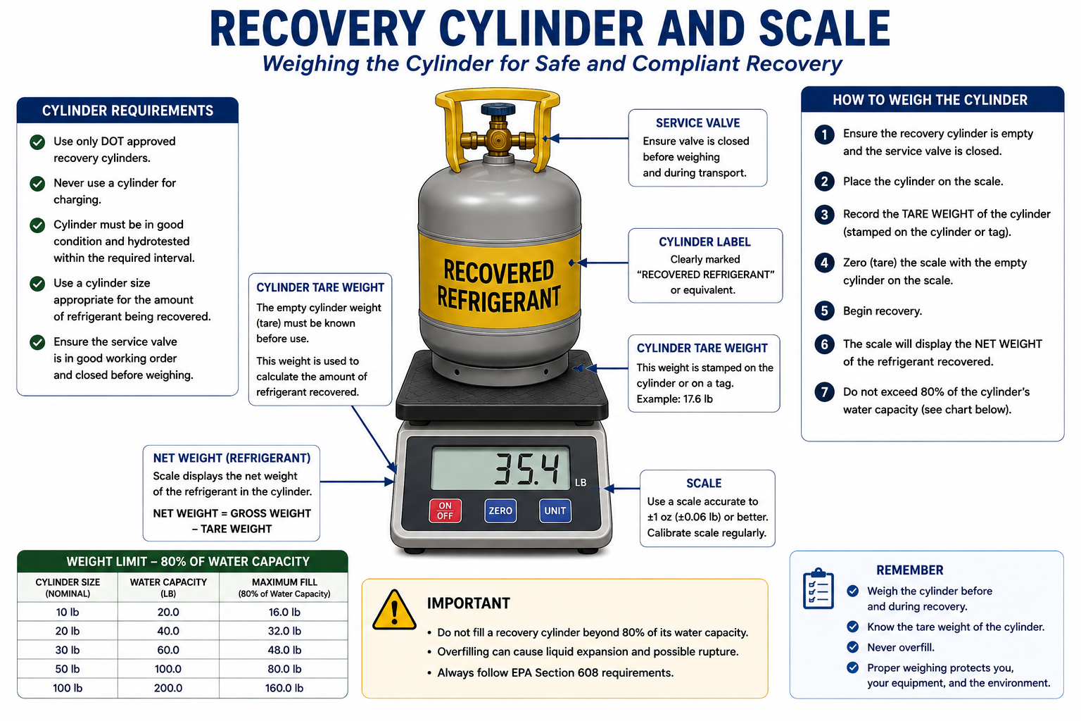
Know the Tare Weight
Tare weight is the weight of the empty cylinder. It provides the starting point for determining how much refrigerant is actually inside.
Monitor Gross Weight
The scale displays the combined weight of the cylinder and its contents. Comparing gross weight with tare weight reveals the refrigerant weight.
Leave Expansion Space
Never liquid-fill a recovery cylinder completely. Refrigerant expansion as temperature rises can create dangerous hydraulic overpressure.
Label the Contents
Clearly identify recovered refrigerant so it is not accidentally mixed with a different refrigerant.
Do Not Estimate Cylinder Fill by Pressure
For a cylinder containing liquid and vapor, pressure primarily reflects refrigerant type and temperature rather than the exact mass of liquid inside. Use the cylinder specifications and a scale to determine allowable refrigerant weight.
Recovery Cylinders Need Vapor Space
HVAC/R recovery procedures commonly use an approximately 80-percent liquid-volume limit so that space remains for liquid refrigerant to expand as cylinder temperature rises. EPA’s incorporated recovery-equipment test procedures also use recovery cylinders filled to an 80-percent level by volume during specified equipment tests.
In actual field work, technicians should determine the permitted refrigerant weight from the cylinder’s water capacity, refrigerant characteristics, cylinder markings, applicable transportation requirements, and manufacturer instructions rather than simply filling until the scale displays an arbitrary percentage of the cylinder’s rated water weight.
Recovery Becomes Harder as Cylinder Pressure Rises
As refrigerant enters the recovery cylinder, the refrigerant can warm and cylinder pressure can rise. The recovery machine must discharge against this pressure. Higher cylinder pressure generally increases the work required of the recovery machine and can slow recovery or cause the machine’s high-pressure protection to operate.
Keeping the recovery cylinder within approved temperature limits and following the recovery-machine manufacturer’s cooling procedures can improve recovery performance. Never apply uncontrolled heat to a recovery cylinder to manipulate pressure.
Never Defeat High-Pressure Protection
If a recovery machine shuts down on high pressure, determine why. Possible causes include a closed valve, restricted hose, excessive cylinder pressure, an overfilled cylinder, or another flow problem. Do not bypass a safety control simply to continue the recovery.
Liquid Is Usually Faster to Move Than Vapor
When a system contains a substantial amount of liquid refrigerant, recovering the liquid first can greatly reduce total recovery time. Moving a pound of refrigerant as liquid requires moving far less volume than moving the same pound as low-density vapor.
After the majority of liquid has been removed, the technician continues recovering vapor until the appliance reaches the required recovery condition.
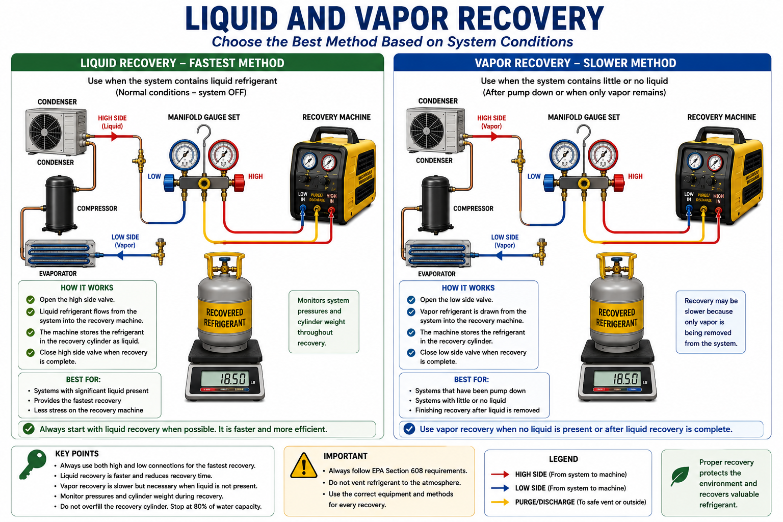
Liquid Recovery
Moves refrigerant efficiently because a large mass of refrigerant occupies a relatively small volume in the liquid state.
Vapor Recovery
Becomes increasingly important after the available liquid has been removed and system pressure falls.
Control Liquid Entering the Machine
Recovery machines differ in how they are designed to handle liquid refrigerant. Some machines are specifically designed to process liquid directly, while others require the technician to meter liquid into the machine to prevent compressor damage or excessive load.
Always follow the recovery-machine manufacturer’s procedure. Do not assume that a machine capable of recovering vapor can accept unrestricted liquid flow.
Liquid Refrigerant Can Damage Equipment
Uncontrolled liquid entering equipment designed primarily for vapor compression can create liquid slugging or excessive mechanical load. Use the recovery machine’s specified liquid-recovery procedure.
Recovery Speed Depends on the Entire Flow Path
A powerful recovery machine cannot overcome every restriction in the system. Small-diameter hoses, Schrader valve cores, partially closed valves, long hoses, clogged filter-driers, and small access fittings can substantially reduce refrigerant flow.
Where the equipment and procedure permit, technicians can improve recovery speed by using short, appropriately sized hoses, fully opening approved flow paths, and reducing unnecessary restrictions.
Shorter Hoses
Reducing hose length reduces pressure drop and internal volume.
Larger Flow Area
Appropriately sized hoses and fittings can increase refrigerant flow compared with highly restrictive connections.
Valve-Core Tools
When appropriate, a valve-core removal tool can reduce a significant flow restriction while allowing the system to remain controlled and sealed.
Clean Filters
A restricted recovery-machine filter or filter-drier can slow recovery and increase machine operating pressure.
A Special Method for Moving Large Quantities of Liquid
Push-pull recovery is a special liquid-transfer method used when a system contains a sufficiently large quantity of liquid refrigerant and the appliance, recovery machine, and cylinder arrangement permit the method.
Unlike ordinary direct recovery through a standard manifold arrangement, push-pull uses the recovery machine to create a pressure difference between the appliance and recovery cylinder. A separate liquid connection allows liquid refrigerant to move directly from the appliance into the receiving cylinder while refrigerant vapor is circulated through the recovery machine to maintain the pressure difference.
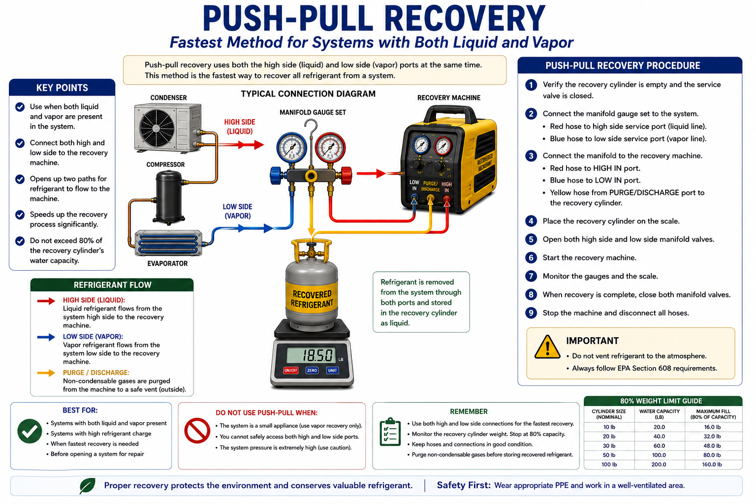
Do Not Set Up Push-Pull From Memory or From a Generic Hose Diagram
Push-pull hose and valve arrangements vary with the recovery machine and appliance. Follow the recovery-machine manufacturer’s approved push-pull diagram and operating instructions. Confirm which appliance connection contains liquid, which cylinder valve is being used, and the direction of vapor flow before opening any valve.
Push-pull is primarily useful for transferring bulk liquid. Once the liquid has been removed, the setup must normally be changed to a conventional direct-recovery arrangement so the remaining vapor can be recovered to the required final condition.
Faster Is Not Always Better
Push-pull recovery is not appropriate for every appliance. Small refrigerant charges may not provide enough liquid to justify the setup. Systems without a usable liquid connection, systems in which liquid is trapped in multiple locations, or equipment whose manufacturer prohibits the method may require conventional liquid and vapor recovery instead.
The technician must also watch cylinder weight continuously because push-pull can move liquid quickly. A rapidly filling recovery cylinder can reach its allowable fill before the technician expects it.
Flammable Refrigerants Require Suitable Equipment
A2L refrigerants have lower flammability than A3 refrigerants, but they still require equipment designed for the associated flammability hazard. A recovery machine that was designed only for nonflammable A1 refrigerants should not automatically be used with an A2L refrigerant.
Recovery equipment for flammable refrigerants must be suitable for those refrigerants and designed so that electrical and mechanical components do not create unacceptable ignition hazards during normal operation.
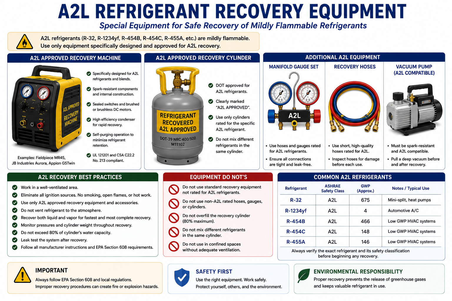
Physical Compatibility Is Not Approval
A hose fitting that connects successfully does not prove that the recovery machine, vacuum pump, leak detector, cylinder, electrical tool, or other equipment is approved for A2L service. Verify manufacturer specifications and equipment certification.
Control the Atmosphere as Well as the Refrigerant
Before recovering an A2L refrigerant, identify and control potential ignition sources and provide ventilation appropriate to the service location. Refrigerant intentionally routed through recovery equipment should remain contained, but hoses, fittings, machine clearing, and accidental leaks can release small amounts into the surrounding area.
The technician should also know where refrigerant vapor could accumulate. Low areas, equipment enclosures, and poorly ventilated spaces deserve additional attention, particularly when a significant charge is being recovered.
Identify the Refrigerant
Confirm the refrigerant from the equipment nameplate and service information before selecting recovery equipment.
Control Ignition Sources
Remove or control flames, sparks, hot work, smoking materials, and other potential ignition sources as required.
Provide Ventilation
Use ventilation appropriate for the work area and possible refrigerant release.
Use Compatible Equipment
Use recovery machines, detectors, cylinders, hoses, and other tools suitable for the refrigerant being serviced.
The Recovery Setup Must Preserve Refrigerant Identity
Recovery equipment, hoses, and cylinders can retain refrigerant after a job is completed. If the same equipment is immediately connected to a different refrigerant without being properly cleared according to the manufacturer’s procedure, the next refrigerant can become contaminated.
Technicians should use proper machine clearing or purge procedures and maintain clear cylinder identification. Dedicated equipment may be appropriate for some refrigerants or applications.
Never Mix Refrigerants in a Recovery Cylinder
Before recovery begins, verify the refrigerant identity and confirm that the recovery cylinder contains the same refrigerant or is properly prepared for the refrigerant being recovered. Cross-contamination can make refrigerant unsuitable for reuse and difficult or expensive to reclaim.
Refrigerant Can Remain Inside the Recovery Machine
After recovery is complete, refrigerant may remain trapped in the recovery machine, hoses, condenser, or internal piping. Many recovery machines provide a purge or self-clearing procedure that transfers most of this remaining refrigerant into the recovery cylinder.
Follow the machine manufacturer’s clearing procedure before disconnecting the equipment or changing refrigerants. Proper clearing reduces refrigerant loss and helps prevent contamination of the next job.
Set Up the Job Before Opening the System
Identify the Refrigerant
Confirm what refrigerant is in the appliance and verify that the recovery machine, hoses, and cylinder are suitable for it.
Inspect the Equipment
Check hoses, seals, machine connections, cylinder valves, electrical cords, gauges, and other recovery equipment for damage.
Check the Cylinder
Verify cylinder condition, refrigerant identity, available capacity, allowable use, and starting weight.
Place the Cylinder on the Scale
Position the cylinder securely on the scale before recovery begins so weight can be monitored continuously.
Connect the Refrigerant Path
For standard manifold recovery, connect the appropriate system ports to the manifold, the center service hose to the recovery machine inlet, and the recovery machine outlet to the recovery cylinder.
Verify Valve Positions
Before starting the machine, identify every valve and confirm the intended direction of refrigerant flow.
Most Recovery Problems Begin Before the Machine Starts
Wrong Cylinder
Using a cylinder that contains another refrigerant can immediately contaminate the recovered charge.
No Scale
Recovering without monitoring cylinder weight removes one of the technician’s primary protections against overfilling.
Closed Cylinder Valve
Starting the recovery machine against a closed discharge path can rapidly raise discharge pressure.
Reversed Machine Flow
Connecting the recovery machine inlet and outlet incorrectly prevents proper recovery and can damage equipment.
Excessive Restrictions
Long hoses, small fittings, valve cores, and partially closed valves can dramatically slow recovery.
Wrong Equipment for the Refrigerant
A recovery machine suitable for one refrigerant category may not be approved for another, especially when flammable refrigerants are involved.
Equipment Performance and Technician Procedure Work Together
EPA establishes minimum recovery and recycling equipment requirements and requires refrigerant to be recovered to applicable levels before covered equipment is opened for service or disposal. The machine can only achieve its intended performance when the technician connects and operates it correctly.
A certified recovery machine connected through badly restricted hoses, an improperly prepared cylinder, or incorrect valve positions may perform poorly even though the machine itself meets EPA equipment standards.
The Machine Does Not Create Compliance by Itself
EPA-certified recovery equipment provides the capability to perform compliant recovery. The technician must still use appropriate procedures, achieve the applicable recovery requirement, prevent avoidable releases, manage the recovery cylinder safely, and follow equipment instructions.
What You Need to Remember
- Recovery equipment used for covered Section 608 work must meet applicable EPA recovery-equipment standards.
- Standard manifold connections are blue/left = low side, red/right = high side, and yellow/center = service connection.
- During standard manifold recovery, refrigerant flows SYSTEM → MANIFOLD → CENTER SERVICE HOSE → RECOVERY MACHINE → RECOVERY CYLINDER.
- The recovery cylinder sits on a scale; refrigerant does not flow through the scale.
- Recovery cylinder weight should be monitored throughout the recovery process.
- A recovery cylinder must retain sufficient vapor space for liquid refrigerant expansion.
- Do not determine cylinder fill by pressure alone.
- Liquid recovery is generally faster than vapor recovery when liquid refrigerant is available.
- After liquid has been removed, vapor recovery continues until the applicable recovery condition is reached.
- Recovery speed can be improved by reducing unnecessary restrictions such as long hoses, small fittings, and valve cores where appropriate.
- Push-pull recovery is a special bulk-liquid transfer method and does not use the same connection arrangement as ordinary manifold recovery.
- Push-pull uses a separate liquid path from the appliance to the recovery cylinder while the recovery machine creates the pressure difference that drives the transfer.
- Push-pull recovery normally must be followed by conventional vapor recovery.
- Push-pull connections should be made according to the recovery-machine manufacturer’s instructions.
- A2L refrigerants require recovery equipment suitable for flammable refrigerant service.
- A fitting that physically connects does not prove that a machine or tool is approved for the refrigerant.
- Recovered refrigerants should be kept separated to prevent cross-contamination.
- Recovery machines may retain refrigerant after operation and should be cleared according to manufacturer instructions.
Review Questions
1. What is the refrigerant flow path during standard manifold recovery?
Answer: Refrigerant flows from the system through the high-side and/or low-side manifold connections, out the center service hose to the recovery machine inlet, through the recovery machine, and then from the recovery machine outlet into the recovery cylinder.
2. What do the blue, red, and yellow manifold hoses normally represent?
Answer: Blue connects to the low side through the left manifold port, red connects to the high side through the right manifold port, and yellow is the center service hose used for equipment such as a recovery machine, vacuum pump, or refrigerant source depending on the operation.
3. Is the recovery cylinder connected to the scale by a refrigerant hose?
Answer: No. The cylinder physically rests on the scale. The scale measures cylinder weight and is not part of the refrigerant flow path.
4. Why is liquid refrigerant normally recovered before vapor when possible?
Answer: A large mass of refrigerant occupies much less volume as liquid than as vapor, so transferring liquid can remove most of the refrigerant much faster.
5. What happens after the available liquid refrigerant has been recovered?
Answer: The remaining refrigerant is recovered as vapor until the appliance reaches the applicable required recovery condition.
6. Why is a scale required during recovery?
Answer: The scale allows the technician to monitor the amount of refrigerant entering the recovery cylinder and prevent the cylinder from being overfilled.
7. How does push-pull recovery differ from ordinary direct recovery?
Answer: Push-pull uses the recovery machine to create a pressure difference that drives liquid refrigerant through a separate liquid line from the appliance directly into the recovery cylinder. It is a special bulk-liquid transfer arrangement rather than the ordinary manifold-to-machine-to-cylinder flow path.
8. Should push-pull hose connections be made from memory?
Answer: No. The technician should follow the recovery-machine manufacturer’s approved push-pull connection diagram and operating procedure because equipment and appliance arrangements can differ.
9. Can a recovery machine approved only for nonflammable refrigerants automatically be used with an A2L refrigerant?
Answer: No. Recovery equipment must be suitable for the refrigerant being recovered, including its flammability classification.
10. Why should the recovery machine be cleared after the job?
Answer: Refrigerant can remain trapped inside the machine and hoses. Proper clearing reduces refrigerant loss and helps prevent contamination when the equipment is later used with another refrigerant.
Lesson 33 Summary
- A complete refrigerant recovery setup includes the appliance, access connections, recovery machine, recovery cylinder, hoses, and scale.
- Recovery and recycling equipment used for covered Section 608 work must meet applicable EPA requirements.
- Blue normally identifies the low-side manifold hose, red identifies the high-side hose, and yellow identifies the center service hose.
- Standard recovery flow is system to manifold, center service hose to recovery machine, and recovery machine to recovery cylinder.
- The recovery cylinder rests on a scale; the scale has no refrigerant connection.
- Recovery-cylinder weight must be monitored so sufficient expansion space remains in the cylinder.
- Cylinder pressure alone does not reliably indicate how much liquid refrigerant is inside.
- Liquid recovery is generally faster than vapor recovery when liquid refrigerant is available.
- Vapor recovery is required after liquid transfer to remove the remaining refrigerant and achieve the required recovery condition.
- Recovery speed is affected by hose size, hose length, access fittings, valve cores, filters, and other restrictions.
- Push-pull recovery is a special method for rapidly transferring relatively large quantities of liquid refrigerant.
- Push-pull uses a separate liquid path between the appliance and recovery cylinder while the recovery machine circulates vapor to create the pressure difference that moves the liquid.
- Push-pull connections must be verified from the recovery-machine manufacturer’s instructions rather than assumed from a standard manifold diagram.
- Push-pull does not eliminate the need for final vapor recovery.
- A2L refrigerant recovery requires equipment suitable for the refrigerant’s flammability characteristics.
- Proper ventilation and ignition-source control remain important during A2L recovery.
- Recovery equipment should be cleared after use according to the manufacturer’s instructions.
- Recovered refrigerants should remain clearly identified and separated to prevent cross-contamination.