BASIC ELECTRICAL FOR THE HVAC TECHNICIAN
What Is Electricity?
Before you can troubleshoot an electrical circuit,
you need to understand what voltage, current,
resistance and electrical charge actually represent.
Electricity is involved in almost everything an HVAC/R
technician works on. Motors, compressors, relays,
contactors, transformers, thermostats and safety controls
all depend on electrical circuits operating correctly.
Why HVAC Technicians Need to Understand Electricity
You do not need to become an electrical engineer to work
on HVAC/R equipment.
You do need to understand enough electricity to know what
the circuit is supposed to do, what your meter is telling
you, and where to look when the equipment does not operate
correctly.
A large part of HVAC/R service work involves electrical
controls and electrical troubleshooting. If you understand
the electrical circuit, many problems become much easier
to isolate.
Atoms and Electrical Charge
To understand electricity, we need to begin with the
basic structure of matter.
Matter is made up of atoms. Atoms contain three particles
that are important to our discussion:
Protons
Protons are located in the nucleus of the atom and
carry a positive electrical charge.
Neutrons
Neutrons are also located in the nucleus, but they
have no net electrical charge.
Electrons
Electrons carry a
negative electrical charge
and occupy regions around the nucleus.
A Neutral Atom
When an atom has the same number of protons and
electrons, the positive and negative charges balance
and the atom is electrically neutral.
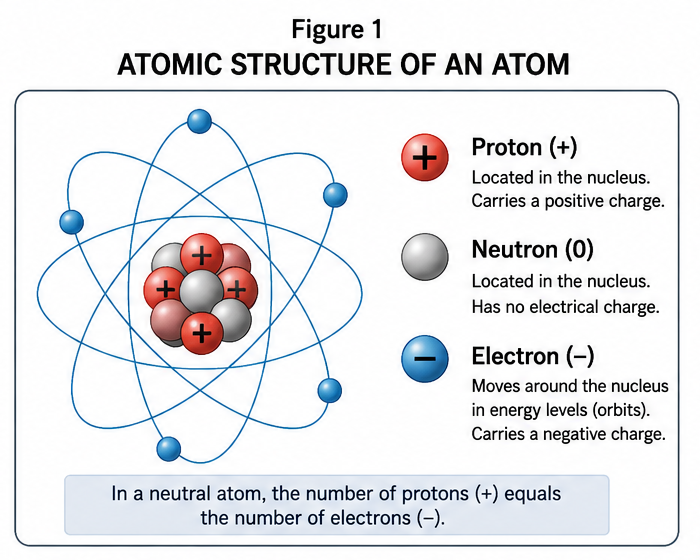
Atomic structure showing protons, neutrons and electrons.
Like Charges Repel and Opposite Charges Attract
Electrical charges interact with each other.
Repel
Repel
Attract
The movement and interaction of electrical charge is part of
what makes electrical circuits possible.
Conductors and Insulators
Some materials allow electrical charge to move much more
easily than others.
Conductors
Conductors allow electrical charge to move relatively
easily through the material.
Copper and aluminum are common conductors used in
electrical wiring.
Insulators
Insulators strongly resist the movement of electrical
charge.
Rubber, many plastics, ceramics and dry air are common
examples of insulating materials.
How Electrical Potential Can Be Produced
Electrical energy can be produced or separated in several
different ways.
Friction
Friction can transfer electrons from one material
to another, producing static electrical charge.
Chemical Action
Batteries use chemical reactions to create an
electrical potential difference between two terminals.
Electromagnetic Induction
Generators produce electrical voltage by moving a
conductor through a magnetic field, or by changing
the magnetic field around a conductor.
Heat
Certain materials can produce a voltage when two
junctions are held at different temperatures.
A thermocouple is a common example.
Voltage, Current and Resistance
These three terms will appear throughout the rest of
this course.
Voltage
Voltage is the electrical potential difference
between two points.
Voltage is measured in volts.
You can think of voltage as the electrical pressure
available to push charge through a circuit.
Current
Current is the rate at which electrical charge flows
through a circuit.
Current is measured in
amperes, or amps.
More current means a greater rate of charge flow.
Resistance
Resistance is opposition to current flow.
Resistance is measured in
ohms.
They Work Together
Voltage, current and resistance are related.
Later in the course, Ohm’s Law will show you how
changing one affects the others.
Do not confuse voltage with current.
Voltage is a difference in electrical potential.
Current is the rate of electrical charge flow.
Alternating Current
The electrical power supplied to most residential and
commercial HVAC/R equipment is alternating current,
usually abbreviated AC.
In an alternating-current circuit, the polarity and direction
of current reverse periodically.
In the United States, the power system normally operates at
60 hertz. That means the AC waveform
completes 60 cycles every second.
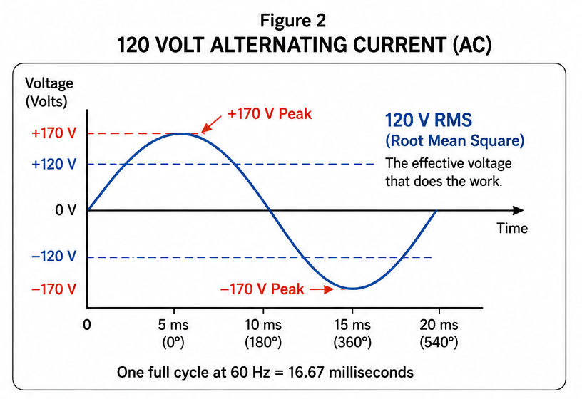
A nominal 120-volt AC waveform. The 120-volt rating is
an RMS value; the instantaneous peak is approximately
170 volts in each direction.
120 volts AC does not mean the waveform peaks at 120 volts.
A nominal 120 V AC supply is approximately 120 V RMS.
For a sine wave, the instantaneous peak is approximately
170 volts positive and 170 volts negative.
Direct Current
Direct current, abbreviated DC, maintains
one polarity.
Batteries are a familiar source of direct current.
Electronic controls inside HVAC equipment may also use DC
even when the equipment itself is supplied with AC power.
Alternating Current
Polarity reverses periodically.
Common for utility and equipment power.
Direct Current
Polarity remains in one direction.
Common in batteries and electronic control circuits.
Line Voltage and Control Voltage
Line Voltage
Line voltage is the voltage supplied to the equipment
from the building electrical system or branch circuit.
Depending on the equipment, common HVAC examples
include 120 V, 208 V, 230/240 V and 460/480 V.
Control Voltage
Control voltage is used to operate thermostats,
relay coils, contactor coils and other control devices.
Many traditional HVAC control circuits use
approximately 24 volts AC.
The Transformer Has Two Different Roles
On the primary side, the transformer is a
load on the line-voltage circuit.
On the secondary side, it becomes the
source for the control circuit.
The same physical component can therefore be a load in
one circuit and a source in another.
The Basic Electrical Circuit
Throughout this course, we will use a simple framework
to understand circuits.
Source
→
Path
→
Switch / Control
→
Load
→
Return to Source
Source
The source provides the electrical potential that
makes current flow possible.
Path
The path is the conductive route through which
current can flow.
Switch or Control
A switch or control determines whether the intended
circuit path is complete.
This may be a mechanical switch, thermostat,
relay contact, safety device or electronic control.
Load
The load uses electrical energy to perform work.
Examples include motors, heaters, compressor windings,
lights, relay coils and contactor coils.
Current requires a complete path back to its source.
Do not think of electricity as simply trying to
“find ground.” Ground may become part of a fault-current
path, but normal circuit current must return to its source.
Basic Schematic Symbols
A schematic is a map of the electrical circuit.
Instead of drawing pictures of the actual components,
we use symbols.
Provides electrical energy
Opens or closes a circuit path
Uses electrical energy to do work
Changes voltage level and provides isolation
Protects the circuit from excessive current
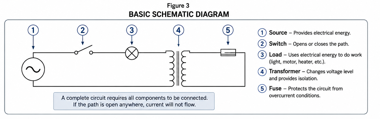
A simplified schematic showing several common electrical
symbols and the complete circuit path.
Do not worry about memorizing every schematic symbol now.
You will see these symbols repeatedly as you move through
the course.
The important skill is learning to follow the circuit from
the source, through the controls and loads, and back to the
other side of the source.
What Is a Short Circuit?
A short circuit is an unintended
very-low-impedance path between points
at different electrical potentials.
Because the resistance or impedance of that path is very low,
current can increase rapidly.
Properly sized fuses and circuit breakers are designed to
interrupt excessive current before wiring or equipment is
seriously damaged.
A short circuit is not simply “a circuit without a load.”
It is an unintended low-impedance path that allows
excessive current to flow.
Electrical Safety
Electricity can injure or kill you.
Do not assume a circuit is safe because the equipment
is not operating.
A switch, thermostat or control may be open while voltage
is still present elsewhere in the circuit.
Use your meter to determine whether voltage is present,
and de-energize circuits before making resistance or
continuity measurements.
Know whether the power is on or off before you touch
the circuit.
Rules to Remember
Protons are positive, electrons are negative,
and neutrons are neutral.
Like charges repel and opposite charges attract.
Voltage is electrical potential difference.
Current is the rate of electrical charge flow.
Resistance opposes current.
A complete circuit requires a path back to the source.
A 120 V AC sine wave is approximately 120 V RMS,
not 120 V peak.
A transformer can be a load in one circuit and a
source in another.
Glossary
- Proton
-
A positively charged particle located in the nucleus
of an atom. - Neutron
- A particle in the atomic nucleus with no net electrical charge.
- Electron
-
A negatively charged particle associated with the region
surrounding an atomic nucleus. - Voltage
-
Electrical potential difference between two points,
measured in volts. - Current
-
The rate of electrical charge flow, measured in amperes.
Current is commonly represented by the letter
I. - Resistance
- Opposition to current flow, measured in ohms.
- Alternating Current
- Electrical current whose direction reverses periodically.
- Direct Current
-
Electrical current that maintains one polarity and
nominal direction of flow. - Line Voltage
-
The voltage supplied to equipment from the building
electrical system or branch circuit. - Control Voltage
-
Voltage used to operate controls such as thermostats,
relays and contactor coils. - Load
- A component that uses electrical energy to perform work.
- Short Circuit
-
An unintended very-low-impedance path between points
at different electrical potentials, often producing
excessive current. - Transformer
-
An electromagnetic device that transfers electrical
energy between circuits and can change voltage level.
In HVAC equipment, the transformer primary acts as a
load on the line-voltage circuit while the secondary
becomes a source for the control circuit.