BASIC ELECTRICAL FOR THE HVAC TECHNICIAN
Build a Circuit
First Shop Project
In this exercise you will build a simple electrical circuit
using the training board. The purpose is not just to make a
light bulb turn on. You are going to identify the basic parts
of the circuit and understand what each one does.
Safety First
This exercise was originally performed in a supervised
classroom using an electrical training board.
Do not reproduce this exercise using household line
voltage as an unsupervised experiment.
If you are following the course independently, use an
appropriate low-voltage training circuit or treat this
lesson as a schematic and wiring exercise unless you
have suitable electrical training, equipment and safety
procedures.
In the original classroom, students did not energize
their circuits until the instructor had inspected
the wiring.
Learning Objectives
By the end of this exercise you should be able to:
Identify the source in the circuit.
Identify the path or conductors.
Identify the switch or control.
Identify the load.
Identify the return path to the source.
Recognize the difference between an open switch
and a closed switch.
What You Are Going to Build
The original training-board exercise used a simple
120-volt AC lamp circuit.
SS — Source
→
SW1 — Switch
→
B1 — Load
→
N — Return
When switch SW1 is closed, the circuit is
complete and current can flow through lamp B1.
The lamp should light.
When SW1 is open, the circuit path is interrupted and the
lamp should be off.
Basic Circuit Wiring Diagram
Study the diagram before beginning the wiring procedure.
You should be able to trace the complete circuit from the
source, through the switch and load, and back to the source.
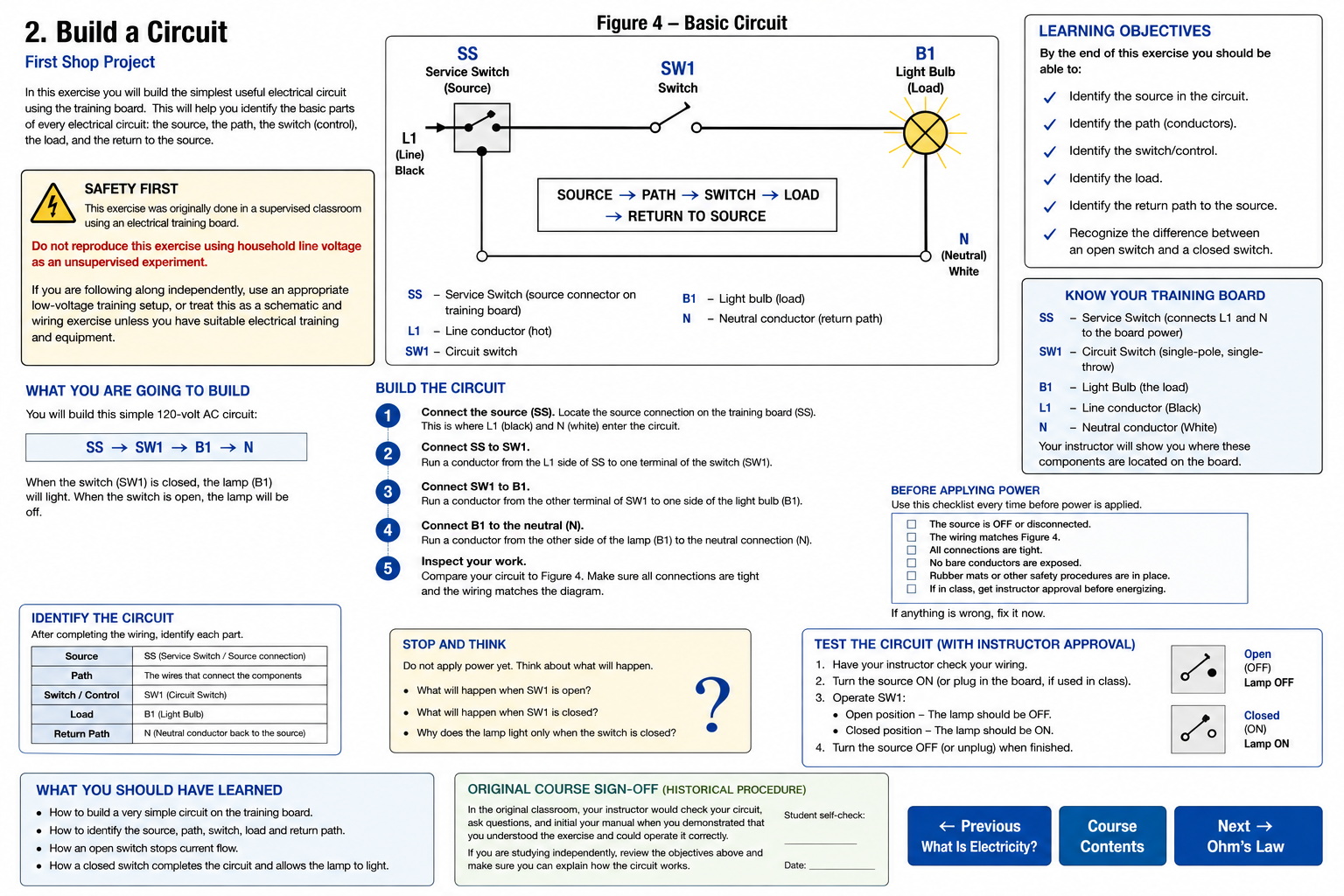
Basic circuit showing the source, circuit switch,
lamp load and neutral return path.
Know Your Training Board
The letters used in this exercise refer to components
on the original classroom training board.
SS — Service Switch
The service switch connects the training board
to its electrical source.
This is where the line and neutral enter the
training-board circuit.
SW1 — Circuit Switch
SW1 is the switch you will use to open and close
the lamp circuit.
B1 — Light Bulb
B1 is the load in this exercise.
When the circuit is complete, electrical energy
is converted into light and heat at the lamp.
L1 and N
L1 is the line conductor supplying
the circuit.
N is the neutral conductor that
provides the normal return path to the source in
this 120-volt circuit.
Build the Circuit
Keep the circuit de-energized while you make the
connections.
1
Locate the Source
Locate SS on the training board.
Identify the L1 line connection and the N neutral
connection.
2
Connect SS to SW1
Run a conductor from the L1 side of SS to one
terminal of switch SW1.
3
Connect SW1 to B1
Run a conductor from the other terminal of SW1
to one side of light bulb B1.
4
Connect B1 to Neutral
Run a conductor from the other side of B1 to
the neutral connection N.
5
Inspect Your Work
Compare your wiring to Figure 4. Trace the circuit
from L1 through SW1 and B1 and then back through
neutral.
Make sure every connection is secure and that
the circuit matches the diagram.
Identify the Circuit
Before applying power, identify each part of the circuit
you just built.
Source
→
Path
→
Switch / Control
→
Load
→
Return to Source
SS / electrical supply
The conductors connecting the components
SW1
B1 light bulb
N neutral conductor back to the source
Stop and Think Before Applying Power
What do you expect to happen when SW1 is open?
What do you expect to happen when SW1 is closed?
Why does the position of SW1 determine whether B1 lights?
Before Applying Power
In the original classroom exercise, the instructor
inspected the circuit before the student was allowed
to energize it.
If something does not look right, fix it before
applying power.
Test the Circuit
In the original supervised shop exercise, the circuit could
now be energized after instructor approval.
If you are independently using this page as a low-voltage
training exercise, follow the safe operating procedure for
your training equipment.
SW1 Open
An open switch breaks the intended circuit path.
B1 should be OFF.
SW1 Closed
A closed switch completes the intended circuit path.
B1 should be ON.
Why does the lamp light?
With SW1 closed, there is a complete conductive path
from the source, through the switch and lamp, and back
to the source. Current can flow through the load.
Open and Closed Circuits
Open Circuit
An open circuit has a break in the intended
conductive path.
In this exercise, opening SW1 stops current through
B1 and the lamp turns off.
Closed Circuit
A closed circuit provides a complete intended
conductive path.
Closing SW1 completes the path through B1 and allows
the lamp to operate.
What You Should Have Learned
A useful circuit needs a source, a conductive path,
a load and a complete return path.
A switch or other control can open or close the
intended circuit path.
An open switch interrupts current through this
series circuit.
A closed SW1 completes the path and allows current
to flow through B1.
In this circuit, neutral provides the normal return
path to the source.
You should be able to trace the entire circuit on
both the wiring diagram and the training board.
Do not stop at “the light came on.”
The important part of this exercise is understanding
why the light came on.
Trace the circuit. Identify the source, path, control,
load and return. Then explain what changes when the
switch opens.
That same thought process will eventually be used on
relays, contactors, thermostats, motors and complete
HVAC systems.
Original Course Sign-Off
In the original classroom course, the instructor checked
the completed circuit, answered questions and initialed
the student’s manual after the student demonstrated that
the circuit was wired correctly and that they understood
how it operated.
If you are studying independently, use the learning
objectives at the beginning of this lesson as your
self-check.
Before moving on, you should be able to look at Figure 4
and explain exactly why B1 is off when SW1 is open and
why B1 operates when SW1 is closed.