Split-System Evaporator Coil Configurations
Direct-expansion evaporator coils are built in several physical configurations so they can fit different equipment cabinets and airflow arrangements.
The most common configurations include A-coils, H-coils, V-coils, and slab coils. The physical shape of the coil changes, but the purpose remains the same: provide enough heat-transfer surface for air to transfer heat into the refrigerant.
Technicians must understand both the coil shape and the direction of airflow through the equipment because installation position, drainage, service access, and condensate management all depend on the actual arrangement.
What You Will Learn
By the end of this lesson you should be able to:
Identify A-coil, H-coil, V-coil, and slab-coil construction.
Describe how coil geometry allows manufacturers to provide large heat-transfer surfaces within different equipment cabinets.
Distinguish upflow, downflow, and horizontal equipment configurations.
Follow return air through the blower, evaporator coil, and supply-air section.
Recognize the relationship between airflow, condensate drainage, access panels, and equipment design.
Understand that equipment airflow direction and manufacturer-approved installation position must also be identified.
Why Are Evaporator Coils Built in Different Shapes?
An evaporator needs a large heat-transfer surface, but that surface must fit inside the available equipment cabinet.
Manufacturers arrange the coil into different shapes so that a large amount of finned surface can fit into a relatively compact space while still allowing air to pass through the coil.
Large Surface Area Is Needed
The evaporator must expose enough heat-transfer surface to the moving air.
Cabinet Space Is Limited
The coil must fit within an air handler, furnace cabinet, fan-coil unit, or dedicated evaporator enclosure.
The Coil Is Arranged Into a Compact Shape
A-coil, H-coil, V-coil, and slab arrangements provide different ways to package the required heat-transfer area.
Common Split-System Evaporator Coil Configurations
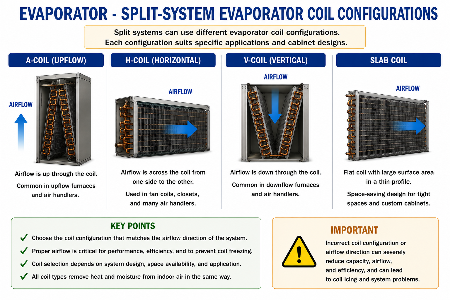
The physical coil shape does not tell you everything about the installation. Always identify the actual airflow direction and manufacturer-approved equipment orientation.
A-Coils
An A-coil uses two inclined coil slabs arranged so that the cross-section resembles the letter A.
This design places a large amount of heat-transfer surface inside a relatively compact cabinet.
Two Coil Slabs
The two finned sections form the sides of the A shape.
Large Heat-Transfer Area
The angled construction provides substantial coil surface while maintaining a central airflow path.
A-coils are commonly found in split-system equipment installed with furnaces and air handlers.
A-Coil in an Upflow Split System
In a typical upflow furnace installation, return air enters near the bottom of the equipment and moves upward.
The blower moves the air through the equipment, and the evaporator coil is normally located on the discharge side of the blower.
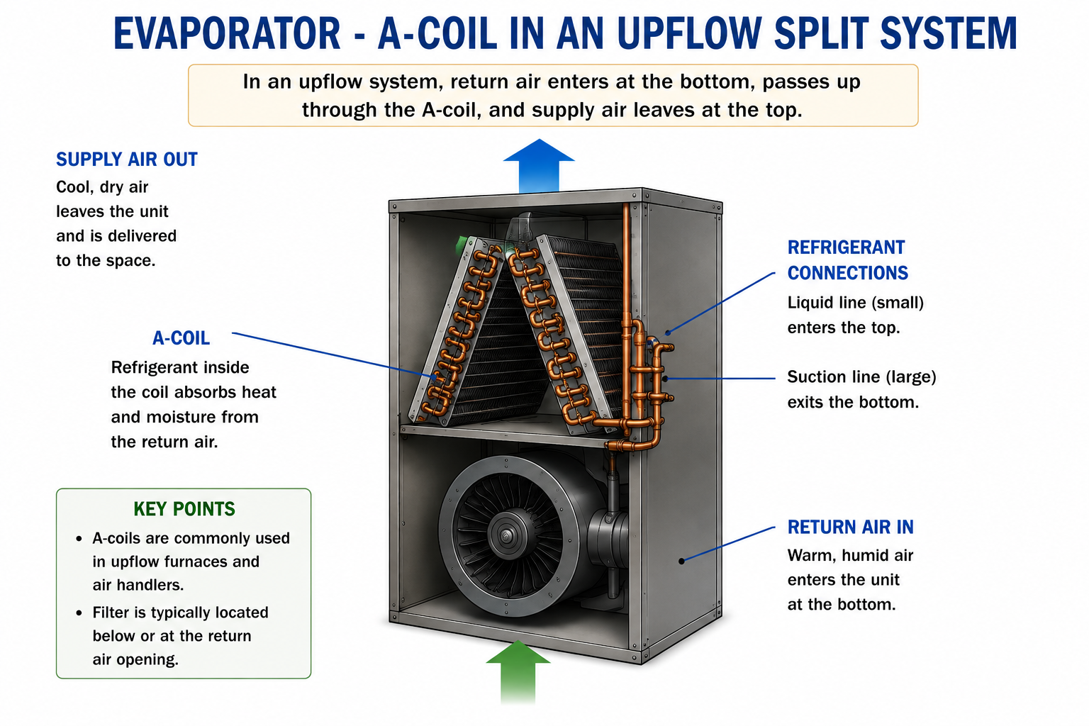
Return Air Enters
Air from the conditioned space enters the return side of the system.
The Blower Moves the Air
The blower increases the air pressure and pushes air toward the evaporator coil.
Air Passes Through the A-Coil
The evaporator removes sensible heat and may remove moisture from the air.
Supply Air Leaves
The conditioned air moves into the supply duct system and returns to the occupied space.
Pressure Relationship
In this common upflow arrangement, the evaporator and condensate drain pan are on the positive-pressure side of the blower.
This pressure relationship becomes important when we study condensate drain traps in the Condensate Management lesson.
H-Coils
An H-coil uses multiple coil sections arranged so that the assembly resembles an H when viewed from the appropriate direction.
The arrangement allows a large amount of evaporator surface to be packaged into a compact cabinet while providing multiple airflow paths through the coil sections.
Multiple Coil Sections
The heat-transfer surface is divided among several finned coil slabs.
Compact Packaging
The configuration allows manufacturers to provide substantial coil area without relying on one large flat surface.
Manufacturer designs vary. Identify the actual airflow path, drain-pan arrangement, refrigerant connections, and approved installation orientation before servicing the equipment.
V-Coils
A V-coil uses two coil slabs arranged in a V-shaped configuration.
Like an A-coil, the angled surfaces allow a relatively large heat-transfer area to fit within a compact cabinet.
Angled Coil Surfaces
Two finned sections form the V-shaped heat exchanger.
Airflow Through Both Sections
The equipment cabinet directs the airflow through the available coil surfaces.
Slab Coils
A slab coil is a relatively flat evaporator heat exchanger rather than an A-, H-, or V-shaped assembly.
Slab coils are particularly useful where cabinet geometry or airflow direction makes a flatter coil arrangement practical.
Flat Heat Exchanger
The refrigerant circuits and fins are arranged in a generally flat coil slab.
Flexible Equipment Applications
Slab coils can be incorporated into equipment where a conventional A-shaped assembly would not fit the intended airflow path.
Upflow, Downflow, and Horizontal Equipment
Coil shape and equipment airflow direction are related, but they are not the same thing.
An evaporator assembly may be designed for one or more equipment orientations depending on the manufacturer and model.
Upflow
Return air enters low in the equipment and conditioned supply air leaves from the upper portion of the system.
Downflow
Return air enters above the evaporator system and conditioned air moves downward toward the supply ductwork.
Horizontal
Air moves generally from one side of the equipment cabinet to the other rather than vertically.
Horizontal Air Handlers
Horizontal air handlers are common where vertical equipment space is limited, such as attics, crawlspaces, and suspended mechanical installations.
The evaporator may be located on the inlet side of the blower, which means the blower is pulling air through the coil.
Blower Pulls Air Through the Coil
The evaporator cabinet can operate below the pressure of the surrounding room or attic.
Condensate Drain Becomes a Negative-Pressure Drain
The pressure difference affects how the condensate piping must be installed.
Negative Pressure Changes Drain Requirements
If the evaporator drain pan is on the inlet side of the blower, the blower can pull air backward through an untrapped drain line.
A properly designed trap is required on a negative-pressure condensate drain. This will be covered in detail in the Condensate Management lesson.
Coil Orientation Affects Condensate Drainage
When an evaporator removes moisture from the air, condensate forms on the coil surfaces and flows toward the drain pan.
The pan and drain connections must be positioned correctly for the approved equipment orientation.
Correct Orientation
The coil, drain pan, and drain connections are positioned so condensate can flow toward the intended outlet.
Incorrect Orientation
An installation that does not match the approved equipment configuration can interfere with condensate collection and drainage.
Do not assume that an evaporator can simply be rotated into another position. Coil, drain-pan, sensor, refrigerant piping, and cabinet arrangements must be compatible with the intended orientation.
Cased and Uncased Evaporator Coils
Split-system evaporator coils may be supplied inside a dedicated sheet-metal cabinet or as an uncased coil assembly intended for installation into another approved enclosure.
Cased Coil
The evaporator is supplied inside a cabinet designed to connect with the furnace, air handler, or duct system.
Uncased Coil
The coil assembly is installed into an approved field or equipment enclosure that provides the required airflow and condensate management.
Regardless of whether the coil is cased or uncased, air must be directed through the heat-transfer surface rather than allowed to bypass around it.
Air Must Pass Through the Coil
Air that bypasses around the evaporator does not receive the intended cooling or dehumidification.
Proper cabinet construction and sealing are therefore important parts of evaporator installation.
Blower Moves Air
The blower creates the pressure difference needed to move air through the equipment.
Cabinet Directs Air Through the Coil
The equipment enclosure should prevent significant airflow from bypassing the evaporator.
The Full Coil Surface Is Used
Proper airflow distribution improves heat transfer and dehumidification across the evaporator.
Configuration Also Affects Service Access
Coil geometry and cabinet orientation determine where the technician can reach the evaporator, drain pan, refrigerant connections, sensors, and other components.
Coil Faces
Both entering-air and leaving-air surfaces may require inspection for dirt, debris, ice, or biological buildup.
Drain Pan
The condensate pan and drain openings must remain accessible for inspection and cleaning.
Refrigerant Connections
The liquid-side inlet and suction-side outlet piping must remain accessible for service.
Equipment Sensors
Modern equipment may include sensors near the evaporator that must not be damaged or relocated during service.
Put the Concepts Together
Evaporator coils are built in different physical configurations to provide large heat-transfer surfaces within different equipment cabinets.
A-coils use two inclined coil slabs arranged in the shape of an A.
H-coils use multiple coil sections arranged into a compact multi-slab configuration.
V-coils use two angled coil slabs arranged in a V shape.
Slab coils use a flatter heat-exchanger arrangement.
Equipment can be designed for upflow, downflow, or horizontal airflow.
Coil orientation affects airflow, condensate collection, drainage, and service access.
An upflow A-coil above the blower commonly operates on the positive-pressure side of the blower.
A horizontal evaporator located on the inlet side of the blower can operate under negative pressure and requires proper condensate trapping.
The equipment manufacturer’s approved orientation must be followed when installing or servicing the evaporator assembly.
Can You Identify Split-System Evaporator Configurations?
You should be able to answer these questions before continuing.
1. Why are evaporator coils built in several different physical shapes?
2. What are the four coil configurations introduced in this lesson?
3. What basic shape forms an A-coil?
4. What is the purpose of an H-coil configuration?
5. How is a V-coil physically arranged?
6. What is a slab coil?
7. What is the difference between coil configuration and airflow orientation?
8. What direction does air move in an upflow system?
9. Where is the A-coil normally located relative to the blower in a typical upflow furnace installation?
10. Why can a horizontal air handler require a condensate trap?
11. Why must the drain pan match the approved equipment orientation?
12. Why should a technician follow the manufacturer’s approved installation position rather than simply rotating a coil?
What You Should Have Learned
A-, H-, V-, and slab-coil configurations are different ways of packaging evaporator heat-transfer surface.
Coil shape does not by itself determine airflow direction.
Split-system equipment may be designed for upflow, downflow, horizontal, or multiple approved orientations.
A typical upflow A-coil is located above the blower and operates on the blower’s positive-pressure side.
A horizontal evaporator located before the blower can operate under negative pressure.
Negative-pressure evaporator drains require proper trapping so blower suction does not interfere with drainage.
Evaporator orientation affects condensate drainage, airflow, access, and service procedures.
Only manufacturer-approved coil and equipment orientations should be used.
Next: Evaporator Superheat
Now that we understand how evaporator coils are physically arranged, the next lesson follows the refrigerant through the evaporator and examines what happens after the final liquid refrigerant boils.
We will define superheat, relate it to refrigerant saturation temperature, and learn how technicians measure and calculate evaporator superheat.
Boiling Ends · Vapor Continues Heating · Superheat Begins