Reciprocating Compressors
Reciprocating compressors use pistons moving inside cylinders to draw in low-pressure refrigerant vapor, compress it, and discharge it as high-pressure vapor.
They have been widely used in domestic and commercial refrigeration systems and are important because their operation clearly demonstrates the mechanical process of vapor compression.
This lesson examines reciprocating compressor construction, piston and valve operation, clearance volume, housing styles, drive arrangements, shaft seals, and common cylinder configurations.
What You Will Learn
By the end of this lesson you should be able to:
Recognize the cylinder, piston, connecting rod, crankshaft, cylinder head, suction valve, and discharge valve.
Describe how the crankshaft and connecting rod cause the piston to move up and down.
Describe what happens to the suction and discharge valves as the piston moves through the cylinder.
Recognize why the space remaining above the piston reduces compressor efficiency.
Identify the important differences in compressor housing and serviceability.
Recognize why a shaft seal is required where the compressor crankshaft passes through the housing.
Identify vertical, V, W, radial, and X cylinder arrangements described in the source lesson.
How a Reciprocating Compressor Works
A reciprocating compressor is a piston-type compressor.
The electric motor turns a crankshaft. Connecting rods transfer that rotating motion to the pistons and create the up-and-down movement known as reciprocating motion.
Technician Point
Rotation at the crankshaft becomes reciprocating motion at the piston.
The piston movement draws refrigerant vapor into the cylinder and then compresses that vapor before it is discharged toward the condenser.
The source notes typical operating speeds of approximately 1725 RPM for older units and 3450 RPM for newer units. :contentReference[oaicite:1]{index=1}
Major Internal Components
The reciprocating compressor contains several mechanical parts that must work together during every revolution of the crankshaft.
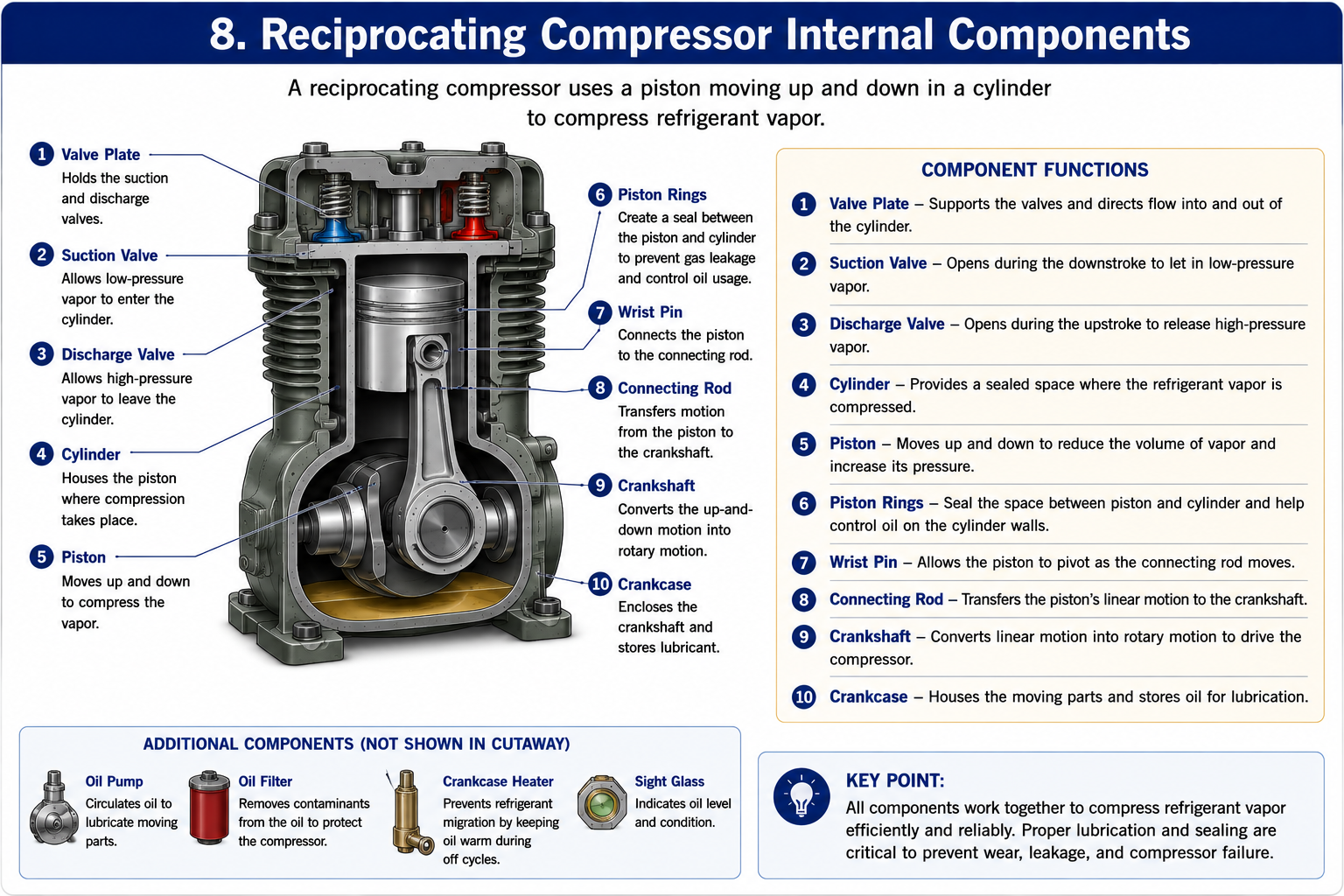
Cylinder
Provides the chamber in which refrigerant vapor is drawn in and compressed.
Piston
Moves up and down inside the cylinder and changes the available volume above it.
Connecting Rod
Connects the piston to the crankshaft and transfers crankshaft rotation into piston movement.
Crankshaft
Rotates with the compressor motor and drives the connecting rod and piston.
Cylinder Head
Closes the top of the cylinder and contains the suction and discharge valve area.
Valves
Control the direction of refrigerant vapor entering and leaving the cylinder.
The source identifies these as the main reciprocating-compressor components. :contentReference[oaicite:2]{index=2}
From Rotation to Reciprocating Motion
The compressor motor produces rotary motion.
The crankshaft and connecting rod convert that rotary motion into the vertical movement of the piston.
Crankshaft Rotates
The motor turns the crankshaft continuously while the compressor operates.
Piston Reciprocates
The connecting rod causes the piston to move repeatedly downward and upward inside the cylinder.
The source describes the crankshaft and connecting rods as changing the rotating motion of the motor into reciprocating motion, producing the up-and-down piston movement. :contentReference[oaicite:3]{index=3}
The Reciprocating Compression Cycle
The piston, suction valve, and discharge valve work together to repeatedly draw in and compress refrigerant vapor.
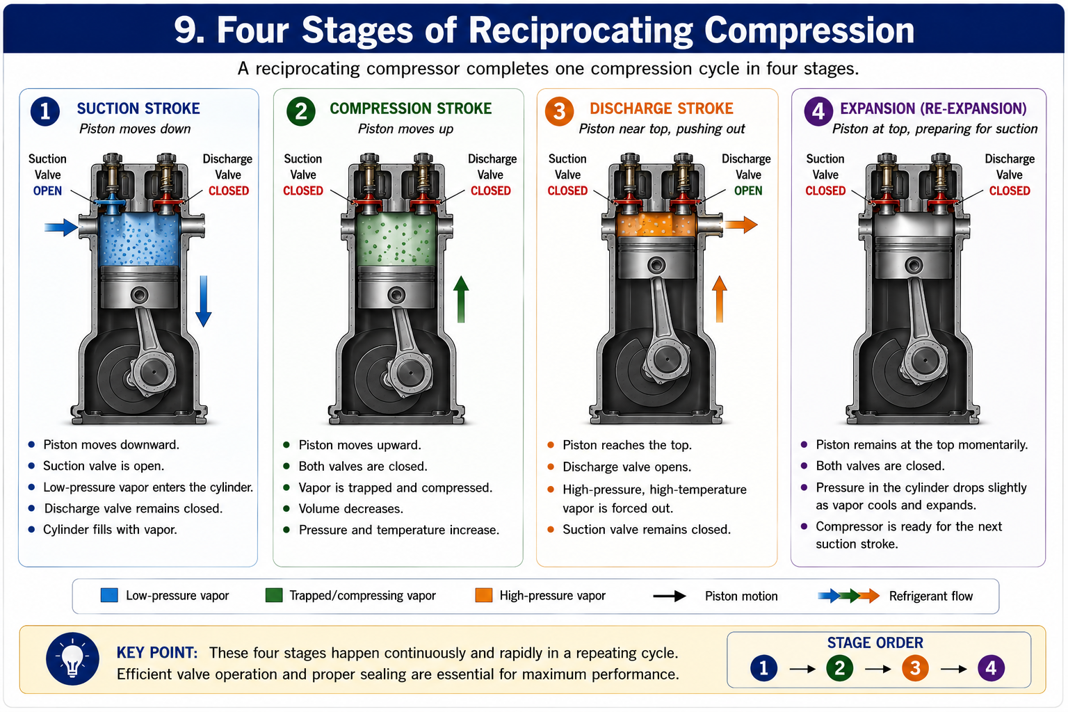
Suction
As the piston moves downward, cylinder pressure decreases and the suction valve opens.
Low-temperature, low-pressure refrigerant vapor enters and fills the cylinder.
Compression Begins
As the piston begins moving upward, the suction valve closes.
The trapped refrigerant vapor occupies a progressively smaller space and its pressure increases.
Discharge
Near the top of the piston stroke, refrigerant pressure and temperature have increased.
When cylinder pressure becomes high enough, the discharge valve opens and high-pressure, high-temperature vapor leaves toward the condenser.
The Cycle Repeats
The piston begins another downward stroke, cylinder pressure falls, and another quantity of low-pressure vapor can enter through the suction valve.
The source describes the suction valve as open with the piston at the bottom, closing as the piston moves upward, and the discharge valve opening after the pressure and temperature have increased sufficiently near the top of the stroke. :contentReference[oaicite:4]{index=4}
Suction and Discharge Valves
The compressor valves respond to pressure differences rather than being mechanically timed like valves in many internal-combustion engines.
Suction Valve
The suction valve allows low-pressure refrigerant vapor to enter the cylinder during the suction portion of the piston stroke.
Discharge Valve
The discharge valve allows compressed high-pressure refrigerant vapor to leave the cylinder after cylinder pressure becomes sufficiently high.
Technician Point
Compressor valves control refrigerant flow in one direction.
If the valves leak or fail to seal correctly, compressor capacity and efficiency will be reduced.
Clearance Volume
The piston does not physically touch the valve plate or cylinder head at the top of its stroke.
A small space remains between the top of the piston and the valve area.
Clearance Volume
The space remaining above the piston at the top of the compression stroke is called clearance volume.
Some high-pressure refrigerant vapor remains trapped in this space after the discharge valve closes.
The source identifies this dead space, or clearance volume, as one reason a reciprocating compressor is not 100 percent efficient. :contentReference[oaicite:5]{index=5}
Why Efficiency Is Reduced
The refrigerant remaining in the clearance space must expand again before the cylinder pressure can fall sufficiently for the suction valve to open.
Reciprocating Compressor Housing Types
The source categorizes reciprocating compressors by housing and drive arrangement.
Three important housing styles are hermetic, semi-hermetic, and open.
Hermetic
The motor and compressor are enclosed inside a single welded shell.
The shell is not designed to be opened for normal field service.
The source notes that these compressors are cooled by suction vapor.
Semi-Hermetic
The motor and compressor are contained inside a common housing that is bolted together.
The housing can be opened, allowing internal compressor components to be serviced.
Depending on design, lubrication may be splash-type or pressure-fed.
Open
The compressor and motor are separate components.
The motor drives the compressor through belts or a special coupling.
Because the crankshaft passes through the compressor housing, an external shaft seal is required.
The source describes the hermetic shell as welded closed, the semi-hermetic housing as bolted and serviceable, and the open compressor as having a separate motor and compressor connected by belts or couplings. :contentReference[oaicite:6]{index=6} :contentReference[oaicite:7]{index=7} :contentReference[oaicite:8]{index=8}
Hermetic Reciprocating Compressors
In a hermetic compressor, the motor and compressor mechanism are enclosed inside one welded shell.
Because the housing is welded closed, normal internal service is not performed without cutting the shell open.
Advantages of the Enclosed Design
There is no external rotating shaft passing through the compressor shell, so an external crankshaft seal is not required.
Service Limitation
The source treats a failed hermetic compressor as a replaceable assembly rather than a compressor normally rebuilt in the field.
Semi-Hermetic Reciprocating Compressors
A semi-hermetic compressor also combines the motor and compressor mechanism in one housing.
The major difference is that the housing is assembled with bolts rather than permanently welded closed.
This allows the housing to be opened for service.
Serviceable Housing
Bolted construction provides access to internal compressor components.
Lubrication
The source describes smaller semi-hermetic compressors as sometimes using splash lubrication and larger units as using pressure lubrication with an oil pump.
Cooling
The source notes that semi-hermetic compressors may use refrigerant-vapor cooling, air cooling, or in some cases water cooling.
The source specifically mentions cooling fins, fans, and water jackets as possible cooling methods on semi-hermetic compressors. :contentReference[oaicite:9]{index=9}
Open-Drive Reciprocating Compressors
An open compressor has a compressor mechanism and motor that are physically separate.
Power is transferred from the motor to the compressor through belts or a coupling.
The source states that open-drive compressors can normally be serviced or rebuilt in the field. :contentReference[oaicite:10]{index=10}
The Shaft Seal Becomes Important
Because the crankshaft extends through the compressor housing, the opening around the shaft must be sealed to prevent refrigerant leakage.
Open-Drive Shaft Seals
Shaft seals are used on open-drive compressors to prevent refrigerant from leaking around the rotating compressor crankshaft.
The source describes shaft seals as using two rubbing surfaces.
Rotating Surface
One sealing surface turns with the crankshaft and is sealed to the shaft.
Stationary Surface
The other sealing surface remains stationary and is mounted to the compressor shaft housing.
The source lists hardened steel and bronze, ceramic and carbon, Teflon, and graphite among possible rubbing-surface materials and notes that the surfaces require lubrication. :contentReference[oaicite:11]{index=11}
Shaft Seal Types Listed in the Source
These four shaft-seal categories are specifically identified in the source presentation. :contentReference[oaicite:12]{index=12}
Piston Quantity and Arrangement
Reciprocating compressors can contain multiple cylinders arranged in different configurations.
The source describes compressors ranging from one to sixteen pistons and identifies several cylinder arrangements. :contentReference[oaicite:13]{index=13}
1–3 cylinders
2, 4, or 6 cylinders
Multiples of 3 cylinders
Multiples of 5 cylinders
Multiples of 4 cylinders
Why Multiple Cylinders?
Multiple-cylinder arrangements allow compressor capacity to be increased while distributing compression work among several pistons.
Optional Oil Cooling
The source also describes an optional oil cooler on some reciprocating compressor models.
It is shown as an additional tubing loop associated with the compressor crankcase and is used to remove heat from the compressor oil.
The source notes that this feature is not present on every model. :contentReference[oaicite:14]{index=14}
System Conditions Affect Compressor Life
A reciprocating compressor does not operate independently from the rest of the refrigeration system.
Conditions elsewhere in the system can directly affect compressor temperature, pressure, efficiency, and life.
Dirty Condenser
A dirty condenser can raise operating pressures and increase compressor temperature.
Improper Refrigerant Charge
Incorrect system charge can also create operating conditions that reduce compressor efficiency and life.
The source specifically warns that dirty condenser coils and improper charges can overheat compressors, raise pressures, reduce efficiency, and shorten compressor life. :contentReference[oaicite:15]{index=15}
Put the Concepts Together
A reciprocating compressor uses pistons moving inside cylinders to compress refrigerant vapor.
The crankshaft and connecting rods convert motor rotation into up-and-down piston movement.
The suction valve opens as cylinder pressure falls during the suction stroke.
The discharge valve opens after the compressed vapor reaches sufficient pressure.
Clearance volume is the space remaining above the piston at the top of the compression stroke.
Hermetic compressors use a welded shell, while semi-hermetic compressors use a bolted serviceable housing.
Open-drive compressors use a separate motor and require a crankshaft seal.
Reciprocating compressors can use several different cylinder and piston arrangements.
Can You Explain Reciprocating Compressor Operation?
You should be able to answer these questions before continuing.
1. What mechanical parts convert crankshaft rotation into piston movement?
2. What happens to the suction valve as the piston moves downward?
3. What happens to cylinder pressure as the piston moves upward?
4. When does the discharge valve open?
5. What is clearance volume?
6. Why does clearance volume reduce compressor efficiency?
7. What is the principal construction difference between hermetic and semi-hermetic compressors?
8. Why does an open-drive compressor require a shaft seal?
9. What are the two rubbing surfaces in an open-drive shaft seal?
10. What piston and cylinder arrangements are identified in the source lesson?
11. How can dirty condenser coils affect compressor life?
12. How can improper refrigerant charge affect compressor operation?
What You Should Have Learned
Reciprocating compressors are positive-displacement compressors that use pistons and cylinders.
The crankshaft and connecting rods produce the reciprocating motion of the pistons.
The suction valve controls vapor entering the cylinder and the discharge valve controls compressed vapor leaving the cylinder.
Clearance volume prevents a reciprocating compressor from achieving perfect volumetric efficiency.
Hermetic compressors are welded closed and normally replaced as assemblies.
Semi-hermetic compressors are bolted together and can be opened for service.
Open compressors use a separate motor and require a shaft seal where the crankshaft passes through the housing.
Reciprocating compressors may contain multiple cylinders arranged vertically or in V, W, radial, or X configurations.
System operating conditions and maintenance directly affect compressor efficiency and life.
Understand the Mechanical Cycle
The reciprocating compressor makes the compression process easy to visualize because each major event can be associated with piston movement and valve operation.
Remember the sequence:
Suction · Compression · Discharge · Repeat
Understanding this mechanical cycle is the foundation for later work with compressor valves, capacity problems, lubrication systems, and compressor diagnostics.