Oil Return, Vertical Risers, and Refrigerant Line Support
Refrigerant piping must do more than carry refrigerant between the indoor and outdoor equipment. The suction line must also allow compressor oil that circulates through the refrigeration system to return reliably to the compressor.
Tubing size, refrigerant velocity, vertical risers, oil traps, support spacing, and line routing all affect oil return. Good installation practice therefore requires both correct refrigerant piping design and proper mechanical support.
What You Will Learn
By the end of this lesson you should be able to:
Explain why compressor oil circulates through the refrigeration system.
Describe how a portion of the compressor oil travels with the refrigerant and must eventually return to the compressor.
Explain the importance of refrigerant velocity.
Describe why sufficient vapor velocity is especially important for carrying oil upward through vertical suction risers.
Explain the difference between horizontal runs and vertical risers.
Recognize why oil return becomes more difficult when suction vapor must carry oil upward against gravity.
Understand the correct use of oil traps.
Explain why oil traps should not be added automatically and why manufacturer piping instructions must be followed.
Apply proper refrigerant-line support practices.
Understand the 2024 IMC maximum support intervals for copper tubing and why closer support may still be necessary.
Recognize harmful sagging and unintended low spots.
Explain how poor support can create oil pockets, vibration, rubbing, and other line-set problems.
Oil Does Not Stay Entirely Inside the Compressor
The compressor requires oil to lubricate bearings, moving surfaces, and other internal components. Although most of the oil remains in the compressor, some oil is carried out of the compressor with the discharged refrigerant vapor.
That oil travels through the refrigeration circuit and must eventually return to the compressor.
A suction line must be large enough to avoid excessive pressure drop but small enough to maintain sufficient refrigerant velocity for reliable oil return. This is one reason refrigerant-line sizing should follow the equipment manufacturer’s requirements rather than being changed by rule of thumb.
The Refrigerant Must Carry the Oil
Oil does not normally flow through the suction line independently of the refrigerant. Returning refrigerant vapor provides the velocity needed to sweep oil through the tubing and back toward the compressor.
Oil Return Can Become Difficult
Oil may collect in low areas of the piping or remain in the evaporator and suction line instead of returning efficiently to the compressor.
Oil Is Carried With the Vapor
Properly sized tubing provides enough refrigerant velocity for oil return while maintaining acceptable suction-line pressure drop.
Pressure Drop Becomes Excessive
Using tubing that is too small may increase velocity, but excessive suction-line pressure drop can reduce capacity and efficiency.
The goal is not simply maximum refrigerant velocity or minimum pressure drop. Correct suction-line sizing balances pressure drop, refrigerant velocity, system capacity, and oil return.
Gravity Changes the Oil-Return Problem
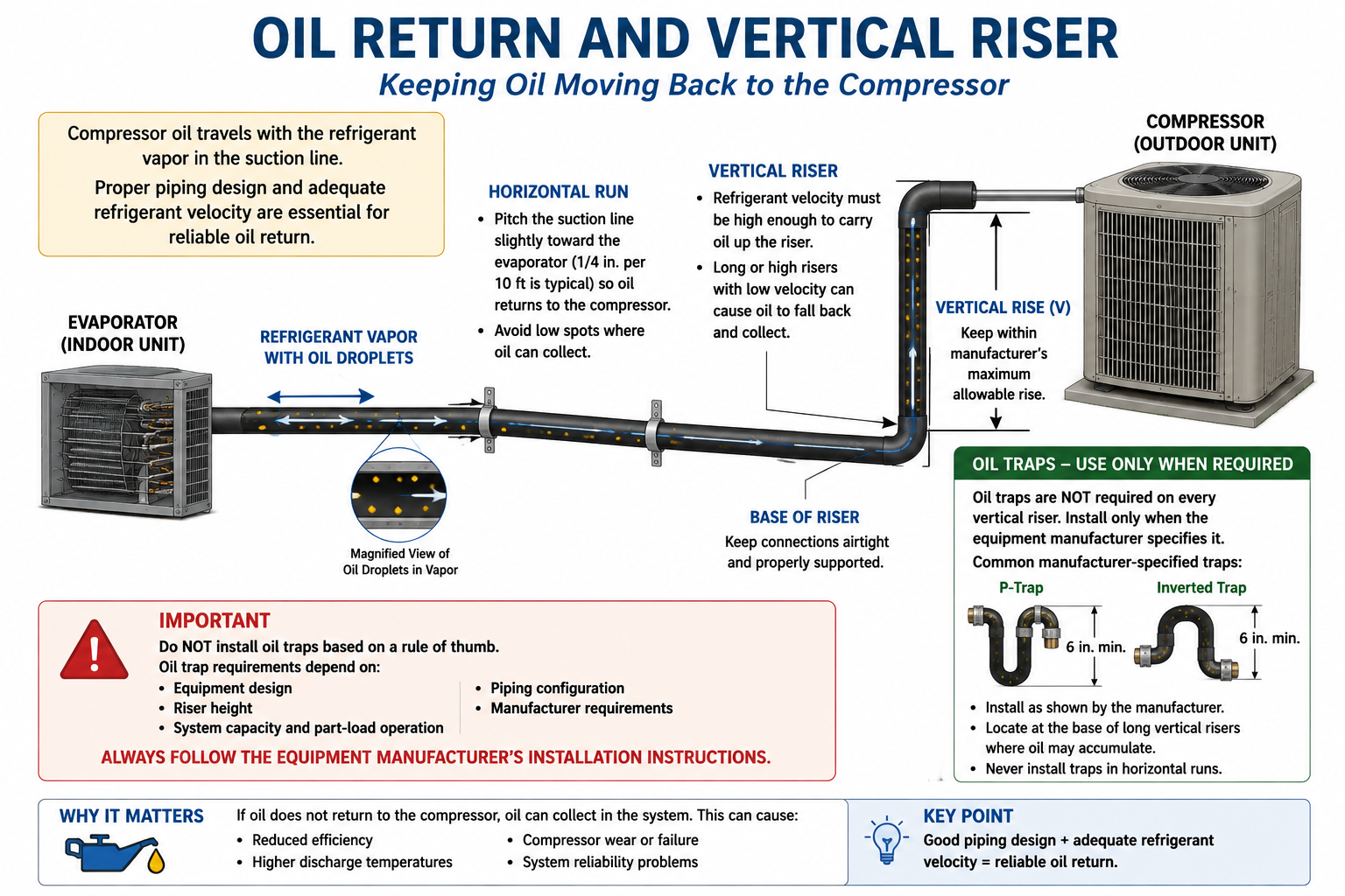
Oil return through a reasonably routed horizontal suction line is generally easier because the refrigerant does not have to lift the oil vertically over a long distance.
A vertical suction riser creates a more demanding condition. Refrigerant vapor must move fast enough to carry oil upward against gravity.
Oil Moves Along the Tubing
Proper routing and support help oil continue moving toward the compressor without collecting in unintended low spots.
Oil Must Be Lifted Upward
Refrigerant vapor must maintain enough velocity to entrain oil and carry it upward through the riser.
A system can have a relatively short total line length but still have a demanding vertical rise. Manufacturer instructions often place separate limits on total tubing length and vertical separation.
Oil Return Becomes More Challenging at Low Capacity
Variable-speed and inverter-driven compressors can operate at much lower refrigerant mass flow than a conventional fixed-capacity compressor.
When compressor capacity decreases, refrigerant velocity in the suction line also decreases. A piping arrangement that returns oil well at full capacity may not necessarily provide the same oil-carrying velocity at minimum capacity.
Higher refrigerant mass flow
Higher suction-line velocity
Lower refrigerant mass flow
Lower suction-line velocity
Do not apply older fixed-capacity piping rules automatically to variable-capacity systems. Manufacturers may specify different tubing sizes, riser arrangements, maximum vertical lifts, or other oil-return provisions.
A Trap Is Not Automatically Required at Every Vertical Riser
An oil trap is a piping configuration designed to collect a small quantity of oil so refrigerant velocity can periodically sweep that oil upward through a vertical suction riser.
Oil traps have long been associated with vertical suction risers, but the technician should not automatically add a trap every time a suction line rises vertically.
Follow the Equipment Piping Instructions
Install traps, double risers, inverted traps, or other oil-management piping only where the manufacturer specifies them or where the engineered piping design requires them.
Rule-of-Thumb Traps Everywhere
An unnecessary trap adds refrigerant-line volume, resistance, oil storage, fittings, and brazed joints without necessarily improving system operation.
Oil return depends on refrigerant type, tubing size, refrigerant velocity, compressor capacity range, vertical rise, equipment design, and system operating conditions. A universal trap rule cannot account for all of these variables.
Sagging Tubing Can Create Its Own Trap
Even when the manufacturer does not require an intentional oil trap, poorly supported refrigerant piping can create unintended low spots.
Oil can collect in these sags rather than continuing toward the compressor. Enough sagging can also create additional vibration, stress, and movement in the piping.
Line remains properly routed and oil continues toward the compressor.
A low spot can collect oil and become an unintended trap.
Proper supports do more than make an installation look neat. They help maintain the intended refrigerant path and prevent sagging locations where oil can accumulate.
Supports Prevent Sagging, Vibration, and Damage
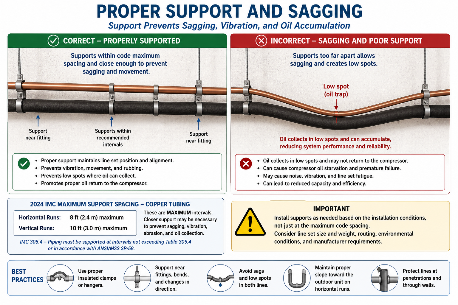
Refrigerant tubing must be supported so it does not sag excessively, move during compressor operation, rub against surrounding materials, or place unnecessary stress on fittings and equipment connections.
Prevent Sagging
Supports maintain the intended tubing path and help prevent low areas where compressor oil can collect.
Control Vibration
Proper support reduces excessive tubing movement and limits vibration transfer into building materials.
Prevent Abrasion
Refrigerant lines should not rub against framing, sheet metal, concrete, or other surfaces that could wear through the tubing.
Protect Connections
Supporting the line set prevents the weight of long tubing runs from being carried by service valves, coils, fittings, or brazed joints.
Maximum Support Intervals for Copper Tubing
The 2024 International Mechanical Code Table 305.4 establishes maximum support intervals for copper or copper-alloy tubing.
Maximum Horizontal Interval
Copper tubing must be horizontally supported at intervals not exceeding 8 feet unless an approved alternative support method applies.
Maximum Vertical Interval
Copper tubing must be vertically supported at intervals not exceeding 10 feet unless an approved alternative support method applies.
An 8-foot horizontal interval is the code maximum for copper tubing, not a requirement to place every support exactly 8 feet apart. Closer support may be necessary to prevent sagging, vibration, abrasion, or oil collection and to comply with the equipment manufacturer’s installation instructions.
The IMC Maximum Is the Same Across Common ACR Tubing Sizes
For the common copper ACR tubing sizes used in refrigerant piping, the 2024 IMC Table 305.4 does not change the basic support interval according to tubing diameter.
| ACR Tubing OD | Maximum Horizontal Support Interval | Maximum Vertical Support Interval |
|---|---|---|
| 3/8 in. | 8 ft | 10 ft |
| 1/2 in. | 8 ft | 10 ft |
| 5/8 in. | 8 ft | 10 ft |
| 3/4 in. | 8 ft | 10 ft |
| 7/8 in. | 8 ft | 10 ft |
| 1 in. | 8 ft | 10 ft |
| 1-1/8 in. | 8 ft | 10 ft |
| 1-3/8 in. | 8 ft | 10 ft |
| 1-5/8 in. | 8 ft | 10 ft |
| 2 in. | 8 ft | 10 ft |
If an installation begins to sag with supports spaced at the maximum permitted interval, additional supports are needed. Good workmanship may require significantly closer spacing than the code maximum.
Place Supports Where the Tubing Needs Them
Regular spacing is important, but support location also matters.
Near Direction Changes
Bends can concentrate tubing weight and vibration. Support the piping so the bend is not carrying unnecessary mechanical stress.
Near Equipment Connections
Do not allow long tubing runs to hang from service valves or indoor coil connections.
At Building Penetrations
Support and protect tubing where it enters or leaves walls, roofs, floors, or equipment spaces.
Where Sagging Begins
If the tubing visibly sags between existing supports, the installation needs additional support regardless of whether the code maximum has technically been exceeded.
The Compressor Causes Refrigerant Lines to Move
Compressors create vibration and pressure pulsations that can travel through refrigerant piping. Proper installation allows normal movement without allowing the tubing to rub, fatigue, or transmit excessive noise into the building.
Allow Controlled Movement
Refrigerant tubing should not be clamped so rigidly that normal thermal expansion and compressor vibration place excessive stress on the copper.
Prevent Rubbing
Use suitable supports or isolation so vibrating tubing cannot rub against sheet metal, framing, masonry, or another refrigerant line.
Protect Insulation
Suction-line insulation should not be crushed or cut by supports. Damaged insulation can later cause condensation problems.
Avoid Noise Transmission
Improperly supported refrigerant tubing can transmit compressor vibration into walls, ceilings, floors, and structural framing.
Larger Soft Copper Requires Additional Attention
The 2024 IMC includes an additional mechanical-protection requirement for larger soft annealed copper refrigerant tubing.
Up to 1-3/8 in. OD
Normal refrigerant-piping support, routing, and protection requirements apply.
Larger Than 1-3/8 in. OD
Soft annealed copper tubing used for field-assembled refrigerant piping must be protected against mechanical damage where required by the applicable code.
A large-diameter soft copper tube can still be dented, flattened, or kinked. Mechanical damage changes the internal flow area and can create an unwanted refrigerant restriction.
What Should a Properly Supported Line Set Look Like?
Correct
Refrigerant lines follow a deliberate route with adequate supports, smooth elevation changes, no unnecessary low spots, protection from abrasion, and no excessive load on equipment connections.
Needs Correction
Lines visibly sag between supports, rub against building materials, hang from service valves, create accidental oil pockets, or move excessively when the compressor operates.
Properly installed refrigerant tubing should not wander, sag, rub, or depend on the equipment connections for support. Good mechanical workmanship supports reliable refrigeration performance.
Oil Return Is Equipment-Specific
The manufacturer determines the approved refrigerant-line sizes, maximum total length, maximum vertical separation, required oil traps, acceptable riser arrangements, and any special requirements for variable-capacity operation.
Line Size
Correct diameter provides the intended balance between pressure drop and refrigerant velocity.
Vertical Rise
Verify the permitted elevation difference between indoor and outdoor equipment.
Oil-Trap Requirements
Install intentional traps only where required by the manufacturer or engineered piping design.
Variable Capacity
Follow manufacturer requirements designed to maintain oil return across the equipment’s complete operating range.
Refrigerant piping practices have changed as compressors, refrigerants, oils, and capacity-control methods have changed. Always use the current installation instructions for the equipment being installed or serviced.
Oil Return and Support Work Together
A small amount of compressor oil circulates through the refrigeration system with the refrigerant.
Returning suction vapor must carry that oil back to the compressor.
Vertical suction risers require sufficient refrigerant velocity to lift oil upward against gravity.
Oil traps are application-specific and should not be installed automatically at every vertical riser.
Poorly supported tubing can sag and create unintended oil traps even when no intentional trap is required.
The 2024 IMC maximum support intervals for copper tubing are 8 feet horizontally and 10 feet vertically.
Closer support may be necessary to prevent sagging, vibration, abrasion, or stress on equipment connections.
Manufacturer piping requirements determine acceptable tubing size, vertical rise, oil-return provisions, and trap requirements for the specific equipment.
Can You Explain Oil Return and Line Support?
You should be able to answer these questions before continuing.
- Why does compressor oil circulate through the refrigeration system?
- How does oil return to the compressor?
- Why is refrigerant velocity important in a suction line?
- Why can vertical suction risers create a greater oil-return challenge than horizontal runs?
- Why can variable-capacity equipment make oil return more difficult at low capacity?
- Should an oil trap automatically be installed at every vertical suction riser?
- What should determine whether an intentional oil trap is required?
- How can sagging refrigerant tubing create an unintended oil trap?
- What is the 2024 IMC maximum horizontal support interval for copper tubing?
- What is the 2024 IMC maximum vertical support interval for copper tubing?
- Why might supports need to be installed closer together than the code maximum?
- Why should refrigerant tubing be supported near equipment connections?
- What problems can occur if refrigerant tubing rubs against building materials?
- Where should the technician obtain the piping requirements for vertical rise and oil return?
What You Should Have Learned
Some compressor oil circulates with refrigerant and must return to the compressor through the refrigeration piping.
Suction-line refrigerant velocity must be high enough to carry oil while pressure drop remains within acceptable limits.
Vertical suction risers require refrigerant vapor to carry oil upward against gravity, making proper tubing size and velocity especially important.
Oil traps are not universal requirements and should be installed only where required by the manufacturer or engineered piping design.
Sagging tubing can create unintended oil traps and should be prevented through proper line-set support.
The 2024 IMC maximum support intervals for copper tubing are 8 feet horizontally and 10 feet vertically.
Supports should also prevent vibration, abrasion, movement, insulation damage, and excessive stress on fittings and equipment connections.
Manufacturer requirements must be followed for line sizing, risers, vertical separation, oil-return provisions, and intentional oil traps.