Line-Set Routing, Protection, and Installation Review
A properly designed refrigerant line set can still fail if the tubing is routed poorly, left unsupported, exposed to mechanical damage, installed with damaged insulation, or allowed to interfere with condensate drainage and equipment serviceability.
This final lesson brings the entire line-set subsection together. The goal is to evaluate the installation as a complete system: tubing size, routing, bends, support, oil return, insulation, refrigerant charge, cleanliness, identification, condensate drainage, protection, and manufacturer requirements.
What You Will Learn
By the end of this lesson you should be able to:
Evaluate refrigerant-line routing.
Recognize direct, deliberate piping routes that minimize unnecessary fittings, pressure drop, sagging, and oil-collection points.
Protect refrigerant piping from physical damage.
Identify areas where tubing can be crushed, kinked, punctured, abraded, or damaged by future construction or maintenance work.
Protect insulation and building penetrations.
Recognize the importance of continuous suction-line insulation, sealed penetrations, and proper support.
Review condensate-drain installation.
Recognize proper slope, trap requirements, support, protection, and termination of condensate piping.
Maintain serviceability.
Route refrigerant piping so service valves, equipment panels, filters, drains, and other components remain accessible.
Perform a complete line-set installation review.
Use the concepts from all previous lessons to evaluate whether the refrigerant piping is ready for reliable operation.
Good Refrigerant Piping Is Deliberate From End to End
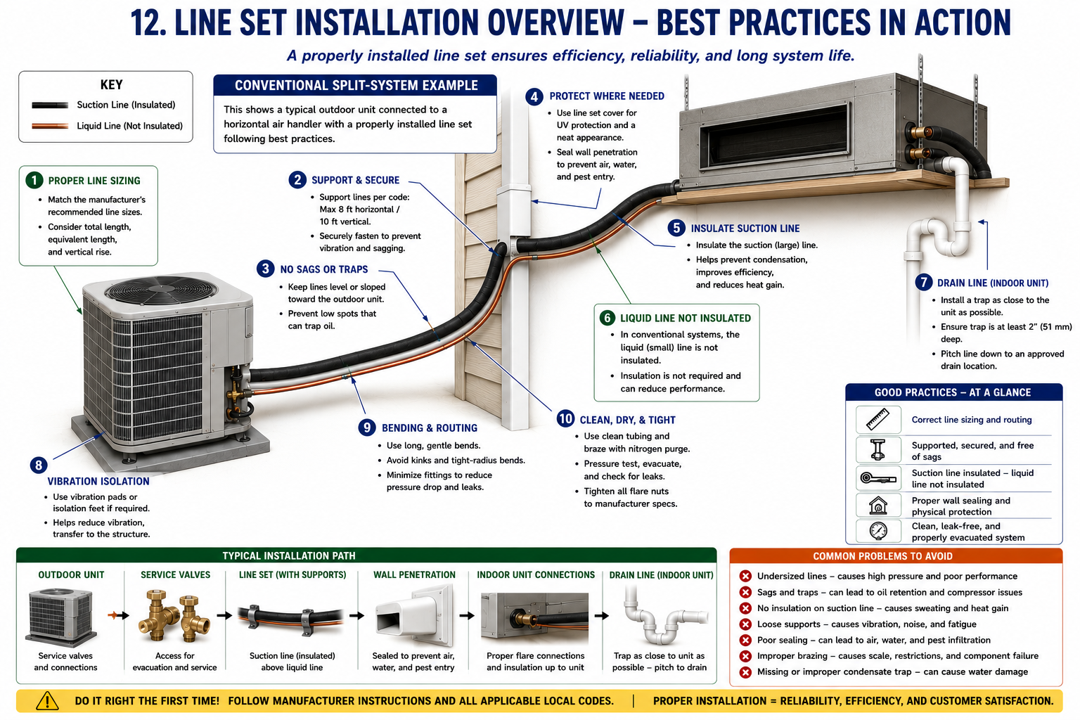
A well-installed line set should look intentional. Tubing should follow a logical path, remain properly supported, avoid unnecessary fittings, stay protected from damage, and maintain access to the equipment.
Mechanical appearance and refrigeration performance are closely related. Sagging, crushed insulation, tight bends, poor support, inaccessible joints, or damaged tubing can all create operating or service problems later.
Use the Shortest Practical Route
The ideal refrigerant piping route is usually the shortest practical path that still allows proper support, gradual bends, protection, drainage, service access, and compliance with manufacturer requirements.
Minimize Unnecessary Distance
Longer tubing adds pressure drop, refrigerant volume, installation cost, and additional charge requirements.
Minimize Unnecessary Fittings
Each fitting adds resistance and another joint that must remain leak-free.
Avoid Unnecessary Low Spots
Poor routing can create unintended oil traps in horizontal or vertical refrigerant piping.
Maintain Service Access
Do not route tubing where it blocks panels, filters, electrical compartments, drains, or service valves.
A slightly longer route may be better if it avoids a sharp bend, inaccessible joint, structural conflict, unsupported span, or location where the tubing is likely to be damaged.
Protect the Tubing Where It Passes Through the Structure
Refrigerant piping often passes through exterior walls, interior partitions, floors, roofs, framing members, and equipment platforms.
Prevent Abrasion
Copper tubing should not rub directly against sharp metal, masonry, framing, or other surfaces.
Maintain Insulation
The suction-line insulation should remain continuous through the penetration where required.
Seal the Opening
Seal the building penetration appropriately against air, water, pests, and weather while maintaining any required rated assembly.
Allow Controlled Movement
Do not wedge the tubing so tightly that normal vibration or thermal expansion creates stress or rubbing.
Refrigerant Tubing Must Survive the Building
Copper refrigerant tubing can be damaged by screws, nails, tools, vehicles, lawn equipment, roofing work, storage, construction activity, or ordinary building maintenance.
Concealed Framing
Protect tubing from nails and screws where required by the applicable code and installation location.
Exterior Runs
Protect line sets from weather, physical impact, landscaping tools, and other outdoor hazards.
Mechanical Rooms
Do not route exposed copper where ladders, stored materials, carts, or service activity are likely to strike it.
Roof Areas
Protect tubing from foot traffic, roofing work, sharp edges, and unsupported spans.
Mechanical damage does not have to create a leak to cause trouble. Flattened or kinked tubing reduces internal flow area and can increase pressure drop.
Prevent Sagging, Movement, and Unintended Oil Traps
Refrigerant piping support requirements were covered earlier in this subsection. During the final review, verify that those supports are actually doing their job.
Horizontal Runs
Verify supports are close enough to prevent visible sagging and remain within applicable code and manufacturer requirements.
Vertical Runs
Ensure the tubing is supported so its weight does not hang from fittings, coils, or equipment connections.
Direction Changes
Provide support where bends or fittings would otherwise carry excessive mechanical stress.
Equipment Connections
Do not allow the service valves or indoor coil connections to support the weight of the line set.
If tubing visibly sags, vibrates excessively, or creates an unintended low point, additional support is required even if the existing spacing appears to fall within the maximum code interval.
Maintain the Full Internal Tubing Area
Inspect every visible bend and fitting for damage, excessive flattening, kinks, unnecessary direction changes, or poor workmanship.
Good Bend
Gradual direction change, tubing remains round, no visible collapse, and adequate support nearby.
Questionable Bend
Noticeable flattening or an unnecessarily tight turn that should be evaluated for restriction.
Damaged Tubing
A kinked, crushed, or sharply flattened tube should be corrected rather than accepted as normal.
Look for Every Place the Vapor Barrier Can Fail
Open Seams
Repair insulation seams that allow humid air to reach the cold tubing.
Exposed Copper
Cover bare suction tubing at fittings, penetrations, repairs, and equipment connections where insulation is required.
Crushed Insulation
Correct hangers or clamps that compress the insulation enough to reduce its thermal performance.
Outdoor Deterioration
Replace or protect insulation damaged by sunlight, weather, animals, tools, or physical contact.
In conventional split-system cooling, the high-pressure liquid line is normally uninsulated unless the equipment manufacturer specifies otherwise. Do not automatically insulate both lines based on ductless-system practice.
The Refrigerant System Can Be Perfect and Still Damage the Building
The indoor evaporator removes moisture from the air during cooling. That water must leave the equipment through a properly installed condensate drain.
Correct Slope
Gravity drain piping should maintain continuous drainage without unintended upward sections or sags that hold water.
Required Trap
Install the trap arrangement required by the air-handler or equipment manufacturer and the pressure condition at the drain connection.
Proper Venting
Where the equipment design requires a vent, install it in the correct relationship to the trap and drain path.
Secure Supports
Support the condensate piping so it does not sag, separate at fittings, or lose the intended slope.
Approved Termination
Terminate the drain where discharge is permitted and where water will not create building damage or nuisance conditions.
Service Access
Provide access for cleaning, inspection, or trap service where required.
Do not install a condensate trap solely because every drain is assumed to need the same configuration. Positive-pressure and negative-pressure air handlers can require different trap arrangements. Follow the equipment manufacturer’s instructions.
Prevent Refrigerant Tubing From Becoming a Sound Path
Compressor vibration can travel through copper tubing and into the building structure if the line set is routed or supported poorly.
Allow Normal Movement
Do not rigidly bind the tubing so tightly that thermal movement or compressor vibration stresses the copper.
Prevent Metal-to-Metal Contact
Use suitable isolation where tubing might contact sheet metal, framing, or another pipe.
Avoid Structural Resonance
Poorly isolated tubing can transmit compressor vibration into walls, ceilings, floors, and roof assemblies.
Check During Operation
Observe the line set with the compressor operating and correct areas that visibly rub, strike, or vibrate excessively.
Install the Line Set So the Equipment Can Still Be Serviced
A line set should not make future service unnecessarily difficult.
Service Valves
Keep adequate access for gauges, probes, recovery equipment, and service-valve operation.
Electrical Panels
Do not route tubing across removable electrical covers or disconnect access.
Filters and Blower Access
Indoor piping should not block filter replacement, blower removal, or coil service.
Drain Components
Maintain access to traps, cleanouts, float switches, and condensate pumps where installed.
An installation that works today but requires tubing to be cut or damaged during normal future service was not routed well.
Leave the System Clearly Identified
Refrigerant identification should remain visible and legible for the life of the equipment where required by the applicable code and manufacturer.
Equipment Nameplate
Verify the refrigerant designation remains readable.
Pipe Identification
Confirm refrigerant and safety-group identification where required by the locally adopted code.
A2L Warning
Preserve required flammable-refrigerant warning information on applicable A2L systems.
Service Documentation
Record final refrigerant charge and installation information where required by code, manufacturer, or service practice.
Check the High-Pressure Liquid Path
In a conventional split system, the liquid line should deliver a reliable supply of high-pressure subcooled liquid refrigerant to the metering device.
Filter-Drier
Verify correct refrigerant-flow direction, component condition, and no significant temperature drop indicating restriction.
Sight Glass
Use a moisture-indicating sight glass for moisture/system-condition information, not as a refrigerant charging tool.
Liquid-Line Routing
Check for kinks, crushed areas, unnecessary fittings, and locations where the pressure could drop enough to cause premature flashing.
Insulation
Remember that the conventional high-pressure liquid line is normally left uninsulated unless manufacturer requirements say otherwise.
Check the Low-Pressure Return Path
Correct Size
Verify the suction-line diameter matches the equipment manufacturer’s piping requirements.
Oil Return
Check vertical risers, low spots, supports, and any manufacturer-required oil-return provisions.
Pressure Drop
Look for excessive length, unnecessary fittings, or restrictions that can reduce compressor suction pressure.
Insulation
Verify continuous insulation and a sealed vapor barrier to prevent condensation and unwanted heat gain.
Review What Happened Before Refrigerant Was Released
A visually attractive line set can still contain internal contamination or moisture if installation procedures were poor.
Tubing Kept Sealed
Open tubing was protected from moisture, dirt, and debris during installation.
Nitrogen Used During Brazing
Internal copper oxide formation was minimized.
Pressure Test Completed
All joints were checked before evacuation.
Evacuation Verified
A micron gauge and manufacturer-approved procedure confirmed the system was sufficiently evacuated.
Confirm the Charge Matches the Installed Piping
Actual Line Length
Verify the installed tubing length used in the charge calculation is correct.
Factory Allowance
Confirm the line length included in the outdoor unit’s factory refrigerant charge.
Additional Refrigerant
Verify any added refrigerant was calculated using the manufacturer-specified rate or procedure and measured by mass.
Final Verification
Confirm refrigerant charge using the manufacturer’s specified operating procedure rather than pressure alone or sight-glass appearance.
Do Not Apply Conventional Assumptions to Every System
Before calling a smaller tube a liquid line or deciding that it should remain uninsulated, determine the actual system design.
Metering-Device Location
Determine whether the EEV is located indoors, outdoors, or elsewhere in the refrigerant circuit.
Operating Mode
Cooling, heating, defrost, and other operating modes can change refrigerant flow direction and condition.
Insulation Requirements
Both refrigerant pipes are commonly insulated on ductless systems where required by the manufacturer.
Piping Network
Check branch lengths, total combined length, vertical separation, refrigerant charge, and approved branch components.
Before the Installation Is Considered Complete
Correct ACR tubing sizes have been verified from the equipment manufacturer’s instructions.
Actual line length, equivalent length, and vertical separation remain within manufacturer limits.
Vertical risers and oil-return provisions match the equipment requirements.
Tubing is adequately supported with no sagging or unintended oil traps.
Bends are smooth, tubing remains round, and no kinks or crushed sections are present.
Refrigerant piping is protected from abrasion, impact, screws, nails, weather, and other mechanical damage.
Suction-line insulation is continuous and sealed, while conventional liquid-line insulation follows manufacturer requirements.
Filter-driers and other directional components are installed in the correct refrigerant-flow direction.
Required refrigerant and A2L identification remains visible and correct.
Brazed joints were made with nitrogen purging and all refrigerant connections passed the required leak test.
The system was evacuated and verified according to manufacturer requirements before refrigerant operation.
Final refrigerant charge accounts for the actual piping installation and has been verified by the specified charging procedure.
Condensate drainage has correct slope, trap arrangement, support, termination, and service access.
Equipment panels, valves, filters, drains, and other service components remain accessible.
The complete installation has been observed during operation for vibration, rubbing, condensation, drainage, abnormal temperatures, and other problems.
A Line Set Is Part of the Refrigeration System
The line set must carry refrigerant with acceptable pressure drop and sufficient velocity for proper system operation and oil return.
ACR tubing is sized by actual outside diameter and should not be confused with nominal plumbing copper sizes.
Line length, equivalent length, vertical separation, bends, fittings, and tubing size all affect refrigerant piping performance.
Proper support prevents sagging, vibration, abrasion, and unintended oil traps.
Filter-driers protect the system, while moisture-indicating sight glasses should not be used as refrigerant charging tools.
Factory refrigerant charge must be adjusted when required for the actual installed piping length and equipment combination.
The conventional suction line is insulated to prevent condensation and unwanted heat gain, while the conventional liquid line is normally uninsulated unless manufacturer requirements state otherwise.
Ductless and variable-capacity systems require technicians to understand metering-device location, operating mode, and manufacturer-specific piping requirements.
Nitrogen purging, leak testing, and evacuation keep the sealed refrigeration circuit clean, dry, and leak-free.
Good routing, protection, drainage, serviceability, and final inspection complete a reliable refrigerant piping installation.
Can You Evaluate a Complete Line-Set Installation?
You should be able to answer these questions before completing this subsection.
- What characteristics make a good refrigerant-line route?
- Why should unnecessary fittings be avoided?
- Why must refrigerant tubing be protected at building penetrations?
- How can a dent or kink affect system operation even if the tubing does not leak?
- Why should line-set supports be added if visible sagging occurs even when the spacing appears to meet the code maximum?
- Why must the suction-line insulation remain continuous and sealed?
- Why is a conventional high-pressure liquid line normally not insulated?
- What should determine whether a condensate drain requires a trap and how that trap is configured?
- Why should refrigerant tubing not block equipment service panels or filters?
- What should be checked on a filter-drier during final system review?
- Why should a moisture-indicating sight glass not be used to determine final refrigerant charge?
- What information should be verified before reusing an existing line set?
- Why is nitrogen used during brazing?
- What is the purpose of the standing-vacuum test?
- Why do ductless systems require a different approach to naming and insulating refrigerant piping?
- What should be checked during final operation of the equipment?
What You Should Have Learned
Refrigerant line sets should follow a direct, deliberate route that minimizes unnecessary length, fittings, pressure drop, and oil-collection points.
Proper support and mechanical protection prevent sagging, vibration, abrasion, kinks, and damage from building construction or maintenance.
Suction-line insulation must remain continuous and sealed to prevent condensation and unwanted heat gain.
Condensate drainage is part of the HVAC installation and must have the required slope, trap arrangement, support, termination, and service access.
Refrigerant piping should remain serviceable and should not block valves, panels, filters, drains, or other components.
Refrigerant identification, A2L warnings, filter-driers, insulation, and piping protection should remain correct and visible after installation.
Brazing cleanliness, leak testing, evacuation, and correct refrigerant charge are as important as the visible mechanical installation.
The complete line-set installation should always be evaluated using the equipment manufacturer’s requirements, the locally adopted code, and actual operating conditions.