Brazing, Nitrogen Purging, Leak Testing, and Evacuation
A refrigerant line set must be clean, dry, leak-free, and mechanically sound before the refrigeration system is placed into operation. Good tubing workmanship does not end when the copper has been cut and fitted together.
Brazing with a low flow of dry nitrogen helps prevent copper oxide scale from forming inside the tubing. After assembly, the system must be pressure tested for leaks and evacuated to remove air and moisture before refrigerant is released or charged into the completed circuit.
What You Will Learn
By the end of this lesson you should be able to:
Explain why nitrogen is flowed during brazing.
Describe how a low flow of dry nitrogen prevents copper oxide scale from forming inside refrigerant tubing.
Recognize the difference between purging and pressure testing.
Explain why brazing purge pressure is very low while leak-test pressure is much higher and controlled separately.
Explain why internal cleanliness matters.
Connect copper oxide, debris, and moisture contamination to filter-driers, metering devices, compressors, and long-term system reliability.
Perform a proper leak-test process.
Understand the role of dry nitrogen, pressure regulators, manufacturer test-pressure limits, and leak detection.
Explain the purpose of evacuation.
Describe why air and moisture must be removed from the sealed refrigeration circuit before operation.
Recognize proper evacuation practices.
Understand the importance of a vacuum pump, micron gauge, large-diameter evacuation hoses, and manufacturer-specified vacuum procedures.
The Inside of the Tubing Must Stay Clean
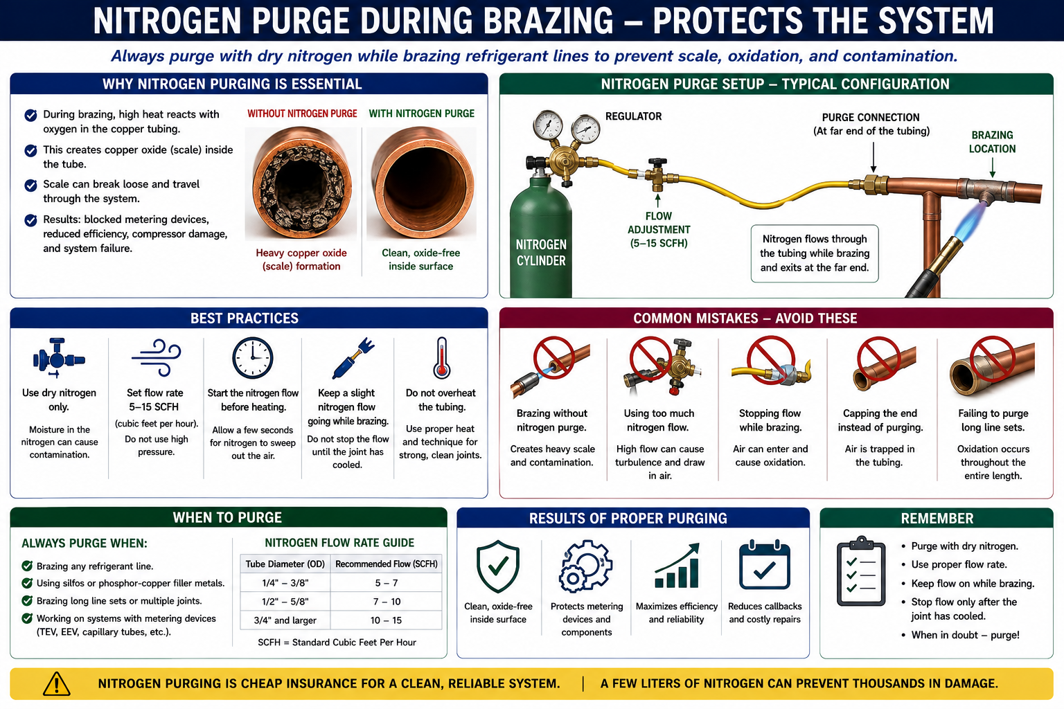
When copper tubing is heated to brazing temperature in the presence of oxygen, oxidation forms on the copper surface. On the outside of the tube this appears as dark scale. The same chemical reaction can occur on the inside of the tubing if air remains inside while the joint is heated.
Cleaner Internal Surface
Dry nitrogen displaces oxygen from inside the tubing and greatly reduces internal oxidation during brazing.
Copper Oxide Scale Forms
Oxygen inside the tubing reacts with the hot copper and can create loose oxide scale that remains inside the refrigerant circuit.
Cleaning the outside of a brazed joint does nothing to remove oxide scale that formed inside the refrigerant line. Internal contamination can circulate through the system after startup.
Contamination Can Travel Through the Entire System
Loose copper oxide particles can be carried through the refrigeration circuit with the refrigerant and oil.
Filter-Drier Loading
Particles can collect in the filter-drier and increase the possibility of a restriction.
Metering-Device Restrictions
Small passages in capillary tubes, fixed orifices, TXVs, and EEVs can be partially or completely blocked by contamination.
EEV Problems
Modern electronic expansion valves can have very small internal clearances that make cleanliness especially important.
Compressor Wear
Contamination circulating with oil can contribute to wear and long-term reliability problems.
A system may appear to operate normally immediately after installation even though oxide scale remains inside the tubing. The resulting restriction or component damage may not appear until later.
Use Nitrogen Intended for Refrigeration Service
Dry nitrogen is an inert gas commonly used in HVAC/R work for brazing purge, pressure testing, and breaking a vacuum between evacuation cycles when the procedure calls for it.
Dry
Nitrogen does not intentionally introduce moisture into the refrigeration circuit.
Inert
It does not support combustion and does not react with copper in the same way oxygen does during brazing.
Controlled
A regulator is used to reduce cylinder pressure to the low flow or test pressure required for the task.
Non-Refrigerant
Nitrogen must be removed from the system before evacuation and refrigerant operation.
Use Flow, Not High Pressure
The purpose of nitrogen during brazing is to displace oxygen from the inside of the tubing. This requires only a small continuous flow.
Brazing purge requires a low flow with an open outlet so pressure does not build inside the tubing. Excessive internal pressure can interfere with brazing alloy flow and create an unsafe condition.
The amount of nitrogen flow needed for purging depends on tubing size and the installation method. The goal is enough flow to displace oxygen without creating pressure that interferes with the joint.
Keep the Joint Clean From Start to Finish
Cut the Tubing Cleanly
Make a square cut without crushing the copper.
Remove Burrs
Deburr carefully so copper chips do not fall into the tubing.
Prepare the Joint
Clean and fit the tubing according to the approved brazing procedure.
Begin Nitrogen Flow
Establish a low flow through the tubing before heating the joint.
Braze the Connection
Heat the joint properly and allow capillary action to draw the brazing alloy into the connection.
Allow the Joint to Cool
Maintain proper workmanship and avoid disturbing the joint while the alloy solidifies.
Heat Must Be Controlled
Service valves, reversing valves, EEVs, TXVs, filter-driers, sensors, insulation, wiring, and other nearby components can be damaged by excessive brazing heat.
Use Heat-Sink Methods
Apply approved heat-control methods where manufacturer instructions require them.
Protect Valve Bodies
Avoid overheating seals, seats, internal components, or service-valve packing.
Move Insulation Away
Keep combustible or heat-sensitive insulation away from the brazing area.
Protect Nearby Surfaces
Use approved shielding to prevent heat damage to walls, siding, framing, wiring, or other materials.
These Are Two Different Uses of Nitrogen
Low Continuous Flow
Used while brazing to displace oxygen and reduce internal oxidation. The system is not sealed under high pressure.
Controlled Test Pressure
Used after assembly to verify the piping and components remain leak-free at the manufacturer-approved test pressure.
The low nitrogen flow used during brazing is not the same as the much higher controlled pressure used later for leak testing.
Verify the Refrigeration Circuit Before Evacuation
After all refrigerant piping connections are complete, the sealed system should be pressure tested using the method specified by the equipment manufacturer and applicable service procedures.
Connect Dry Nitrogen
Use a regulator rated for the cylinder and the required test procedure.
Pressurize Gradually
Increase pressure in a controlled manner rather than applying full cylinder pressure directly to the refrigeration system.
Stay Within Approved Pressure
Do not exceed the equipment manufacturer’s specified pressure-test limits or the rating of the lowest-pressure component in the circuit.
Check Every Joint
Inspect brazed joints, flare connections, service valves, branch fittings, and other possible leak points.
Allow Stabilization
Pressure can change with temperature. Interpret test-pressure changes with ambient and tubing temperature in mind.
Repair Before Evacuation
Do not proceed to evacuation until known leaks have been corrected and the system passes the required leak test.
Use More Than One Clue When Necessary
Bubble Solution
Approved leak-detection solution can identify gas escaping from accessible joints.
Electronic Leak Detector
An appropriate detector can help locate small refrigerant or tracer-gas leaks when used according to its instructions.
Pressure Stability
A properly controlled standing-pressure test can reveal loss of pressure over time, but temperature changes must be considered.
Visual Inspection
Inspect flare surfaces, brazed joints, tubing damage, valve caps, and other likely leak locations.
Use approved dry nitrogen or another manufacturer-approved inert test gas. Oxygen can create a serious fire or explosion hazard when exposed to refrigerant oil or other combustible materials under pressure.
Air and Moisture Do Not Belong in the Refrigeration Circuit
After the system passes the leak test, nitrogen and other noncondensable gases must be removed before refrigerant operation.
Air
Noncondensable gases can increase condensing pressure and interfere with normal heat transfer.
Moisture
Water can react with refrigerant and oil, contribute to acid formation, freeze at restrictions, and damage components.
Water Vapor
Moisture trapped in the system must be removed as vapor during evacuation.
Residual Nitrogen
Nitrogen used for leak testing must be released safely before connecting the vacuum pump.
Lower Pressure Helps Remove Moisture
Reducing the pressure inside the refrigeration circuit lowers the boiling temperature of water. Under a sufficiently deep vacuum, moisture can vaporize at temperatures far below its normal atmospheric boiling point.
Evacuation removes gases and moisture vapor. Moisture trapped in oil, insulation, or low areas may require time and a sufficiently deep vacuum to vaporize and leave the system.
Measure the Vacuum at the System
A compound pressure gauge is not precise enough to verify a deep refrigeration vacuum. A micron gauge is used to measure absolute pressure at very low pressure levels.
Measures Absolute Pressure
The micron gauge indicates how deeply the system has been evacuated.
Install Away From the Pump
Where practical, measure vacuum at the refrigeration system rather than directly at the vacuum-pump inlet so the reading better represents system condition.
Use Manufacturer Target
Follow the equipment manufacturer’s specified evacuation level and standing-vacuum test rather than relying on one universal target for every system.
Watch Vacuum Decay
A rise in pressure after isolating the pump can help indicate remaining moisture, leakage, or trapped gas.
Flow Restriction Matters During Evacuation Too
A vacuum pump can only remove vapor as quickly as the hoses, valve cores, fittings, manifolds, and service ports allow it to flow.
Large, Short Evacuation Path
Large-diameter vacuum-rated hoses and core-removal tools can reduce restriction and speed evacuation.
Small, Restrictive Path
Long small-diameter hoses, valve cores, and restrictive manifolds can greatly slow moisture and vapor removal.
Evacuation speed depends on both pump capacity and conductance through the connections between the pump and the refrigeration system.
Reaching the Target Is Not the Only Check
After the specified vacuum level is reached, the vacuum pump may be isolated from the system so the technician can observe how the pressure changes.
System May Be Dry and Tight
A properly evacuated leak-free system should remain within the manufacturer’s acceptable standing-vacuum criteria.
Moisture May Remain
Moisture can continue vaporizing after the pump is isolated, causing the micron reading to rise.
Possible Leak
A continuous pressure increase can indicate leakage, although diagnosis should follow the approved test procedure.
Evaluate the target vacuum, how quickly the system reaches it, how the vacuum behaves after isolation, the size and condition of the system, and the manufacturer’s procedure.
Some Procedures Use Nitrogen Between Vacuum Cycles
For wet systems or where specified by service procedures, evacuation may be interrupted by introducing dry nitrogen and then evacuating again.
Triple evacuation is a service method, not a substitute for preventing moisture from entering the system in the first place. Keeping tubing sealed and completing installation efficiently remains the best starting point.
Use Tools and Procedures Approved for the Refrigerant
When working on equipment using an A2L refrigerant such as R-32 or R-454B, service equipment and work procedures must be suitable for the refrigerant and task being performed.
Vacuum Pump
Use equipment suitable for the refrigerant application and follow manufacturer safety requirements.
Recovery Equipment
Use recovery equipment approved for the refrigerant safety classification.
Leak Detection
Use a leak detector appropriate for the refrigerant being serviced.
Ignition Control
Follow A2L procedures for ventilation, ignition-source control, and equipment safety during installation and service.
Problems That Can Be Prevented
Brazing Without Nitrogen
Allows internal copper oxide scale to form.
Too Much Nitrogen During Brazing
Can pressurize the tubing and interfere with proper brazing-alloy flow.
Exceeding Test Pressure
Can damage equipment, valves, coils, or other components.
Skipping Leak Testing
Can result in refrigerant loss after startup and require the system to be reopened.
Evacuating Through Restrictive Hoses
Can make evacuation unnecessarily slow and difficult.
Checking Vacuum Only at the Pump
Can give a misleading impression of system vacuum if there is substantial restriction between the pump and the refrigeration circuit.
From Open Tubing to a Ready Refrigeration Circuit
Keep refrigerant tubing capped or sealed until it is ready to be connected.
Cut, deburr, fit, and prepare the tubing without allowing debris to enter the refrigerant circuit.
Flow a low amount of dry nitrogen through the tubing while brazing to reduce internal oxidation.
After piping is complete, pressure test the refrigeration circuit with dry nitrogen using the manufacturer’s specified test pressure and procedure.
Locate and repair leaks before proceeding.
Release test nitrogen safely and connect the vacuum equipment.
Evacuate the system to the manufacturer’s specified vacuum level and verify it with a micron gauge.
Complete the required standing-vacuum test before releasing or charging refrigerant into the system.
Can You Explain Brazing, Leak Testing, and Evacuation?
You should be able to answer these questions before continuing.
- Why is dry nitrogen flowed through copper tubing during brazing?
- What happens inside copper tubing when it is brazed in the presence of oxygen?
- How can copper oxide scale affect filter-driers and metering devices?
- Why should nitrogen flow during brazing remain low?
- Why must an outlet remain open while nitrogen is flowing during brazing?
- What is the difference between a nitrogen brazing purge and a nitrogen pressure test?
- Why must the pressure regulator be used when pressure testing?
- Where should the allowable pressure-test value come from?
- Why should oxygen never be used for refrigeration-system pressure testing?
- Why must air be removed from the refrigeration system?
- Why must moisture be removed before operation?
- Why is a micron gauge required for deep-vacuum measurement?
- Why is it preferable to measure vacuum at the system rather than only at the vacuum pump?
- How can small hoses and valve cores slow evacuation?
- What can a rising micron reading after pump isolation indicate?
- Why are proper service tools especially important when working with A2L refrigerants?
What You Should Have Learned
Dry nitrogen is flowed through refrigerant tubing during brazing to displace oxygen and reduce internal copper oxide formation.
Copper oxide and other contamination can restrict filter-driers and metering devices and contribute to long-term system reliability problems.
Brazing purge uses low nitrogen flow, while leak testing uses a controlled higher pressure after the piping system has been completed.
The refrigeration system must be pressure tested at the manufacturer-approved pressure before evacuation.
Air and moisture must be removed because they can increase operating pressures, reduce performance, form acids, freeze at restrictions, and damage system components.
A vacuum pump lowers system pressure so moisture can vaporize and be removed from the refrigerant circuit.
A micron gauge is used to verify deep vacuum and evaluate system condition after the pump is isolated.
Proper brazing, leak testing, and evacuation keep the refrigeration circuit clean, dry, leak-free, and ready for reliable operation.