Ductless and Variable-Capacity Refrigerant Piping
Ductless mini-splits, multi-splits, VRF equipment, and other variable-capacity systems use the same basic vapor-compression refrigeration cycle as conventional split systems, but the refrigerant piping does not always function like a traditional liquid line and suction line.
Metering-device location, operating mode, compressor speed, indoor-unit combination, and control strategy can all change the refrigerant condition inside the connecting tubing. For this reason, technicians must understand the equipment design instead of identifying refrigerant state only by tubing size.
What You Will Learn
By the end of this lesson you should be able to:
Explain why ductless piping differs from a conventional split system.
Recognize that the metering device may be located in the outdoor unit rather than directly ahead of the indoor evaporator.
Identify refrigerant state from system design.
Explain why tubing diameter alone does not prove that a pipe contains high-pressure liquid or low-pressure suction vapor.
Explain variable-capacity operation.
Recognize how inverter-driven compressors and electronic expansion valves continually change refrigerant mass flow.
Understand ductless insulation requirements.
Recognize why both refrigerant pipes are commonly insulated on ductless equipment.
Explain why piping limits are especially important.
Understand manufacturer requirements for individual branch length, total piping length, vertical separation, charge adjustment, and indoor-unit combinations.
Install refrigerant piping and condensate drains correctly.
Recognize the importance of support, insulation, routing, drainage, protection, and manufacturer-approved installation practices.
Where Is the Metering Device?
In the conventional cooling-only split system discussed earlier in this subsection, the metering device is commonly located at or immediately ahead of the indoor evaporator.
In this arrangement, calling the smaller tube the liquid line is thermodynamically accurate during cooling because the refrigerant has not yet passed through the metering device.
The location of the metering device determines where the major refrigerant pressure drop occurs. Move the metering device to another location and the refrigerant condition in the connecting piping can change.
The EEV May Be in the Outdoor Unit
Many ductless and variable-capacity systems use an electronic expansion valve located in the outdoor unit. In that arrangement, refrigerant can pass through the metering device before traveling through the connecting tubing toward the indoor coil.
If refrigerant has already passed through an outdoor electronic expansion valve, the smaller connecting tube may not contain the same high-pressure subcooled liquid found in the liquid line of a conventional split system.
A Small Pipe Does Not Automatically Mean Liquid
Technicians often learn that the smaller tube is the liquid line and the larger insulated tube is the suction line. That description works well for many conventional cooling systems but should not be treated as a universal refrigeration rule.
Where Is the Metering Device?
Determine whether refrigerant has already undergone its major pressure drop before entering the connecting piping.
What Mode Is the Equipment In?
Cooling, heating, defrost, oil-return, and other operating modes can change refrigerant direction and condition.
What Is the Controller Doing?
EEV position and compressor capacity continually change refrigerant mass flow and operating pressures.
What Does the Manufacturer Call the Pipe?
Use terms such as gas pipe, liquid pipe, refrigerant pipe, vapor pipe, or connection pipe according to the equipment documentation.
Knowing what refrigerant is actually doing inside the tube is more important than memorizing a name for the pipe.
Refrigerant Flow Changes Continuously
A conventional fixed-capacity compressor tends to operate either on or off. Inverter-driven compressors can operate across a wide capacity range.
Reduced Compressor Speed
Refrigerant mass flow decreases and the EEV adjusts to maintain the required evaporator operating condition.
Intermediate Capacity
The compressor and electronic metering device operate at an intermediate point rather than simply switching fully on or off.
Higher Compressor Speed
Refrigerant mass flow increases and the EEV responds to the greater system load.
Variable refrigerant mass flow means refrigerant velocity through the piping changes as equipment capacity changes. This is one reason piping sizes and allowable lengths must come from the equipment manufacturer.
The Refrigerant Piping Is Part of a Control System
In modern ductless and variable-capacity equipment, the compressor and EEV often operate together as part of a closed control system.
Measure temperatures, pressures, and operating conditions
Calculates required system response
Adjust capacity and refrigerant flow
The result is a refrigeration system in which pressure, refrigerant flow, line temperature, and compressor speed can change significantly without the equipment actually being malfunctioning.
Ductless Insulation Requirements Differ From Conventional Split Systems
In the previous lesson, we established that the conventional high-pressure liquid line is normally not insulated while the cold suction line is insulated.
Many ductless manufacturers require both refrigerant pipes to be insulated.
Typical Arrangement
Large suction line insulated. Smaller high-pressure liquid line normally uninsulated unless the manufacturer specifies otherwise.
Follow Manufacturer Requirements
Both refrigerant pipes are commonly insulated because refrigerant temperature and operating mode can make either pipe subject to unwanted heat transfer or condensation.
The smaller pipe on a ductless system should not be treated automatically like the bare liquid line of a conventional split system. Install the insulation exactly as required by the equipment manufacturer.
Multi-Zone Systems Can Have Several Different Length Limits
A single-zone ductless system may have one pair of refrigerant pipes between the outdoor unit and indoor unit. A multi-zone or VRF system can have several indoor units, branch components, headers, or distribution devices.
Individual Branch Length
The manufacturer may limit the piping distance from a branch point or outdoor unit to each individual indoor unit.
Total Combined Length
The sum of all refrigerant piping may have a separate maximum value.
Vertical Separation
Limits may apply between outdoor and indoor units and sometimes between different indoor units.
Distance After Branching
Some systems limit the allowable piping distance between branch components and individual indoor units.
Multi-zone piping design often requires checking several different distance and elevation limits simultaneously.
Additional Charge May Depend on the Complete Piping Network
Ductless and variable-capacity equipment may be factory charged for a specified amount of piping, but charge adjustment can become more complex on multi-zone systems.
Total Piping Length
The manufacturer may calculate additional refrigerant from the total installed piping length.
Pipe Diameter
Some calculations account for the amount of each tubing size installed.
Indoor Unit Combination
The number and capacity of connected indoor units may affect the required system charge.
Branch Components
Headers, branch boxes, and distribution components can affect the approved installation and refrigerant quantity.
Do not use a conventional split-system ounces-per-foot assumption on a multi-zone ductless or VRF system. Follow the manufacturer’s calculation procedure for the complete piping network.
Many Ductless Systems Use Mechanical Refrigerant Connections
Ductless systems commonly use flare connections at indoor units and sometimes at outdoor-unit service valves. These joints must be prepared and tightened according to the manufacturer’s requirements.
Cut Tubing Squarely
A poor tubing cut can make it difficult to form a uniform flare.
Remove Burrs Correctly
Deburring should not allow copper chips to fall into the refrigerant tubing.
Form the Correct Flare
The flare must match the tubing, fitting, refrigerant application, and manufacturer requirements.
Torque the Connection
Use the specified tightening torque rather than judging the connection only by feel.
Overtightening a flare can damage or split the flare surface. Undertightening can allow leakage. Correct installation requires the specified torque.
Good Workmanship Applies to the Entire Indoor-Unit Installation
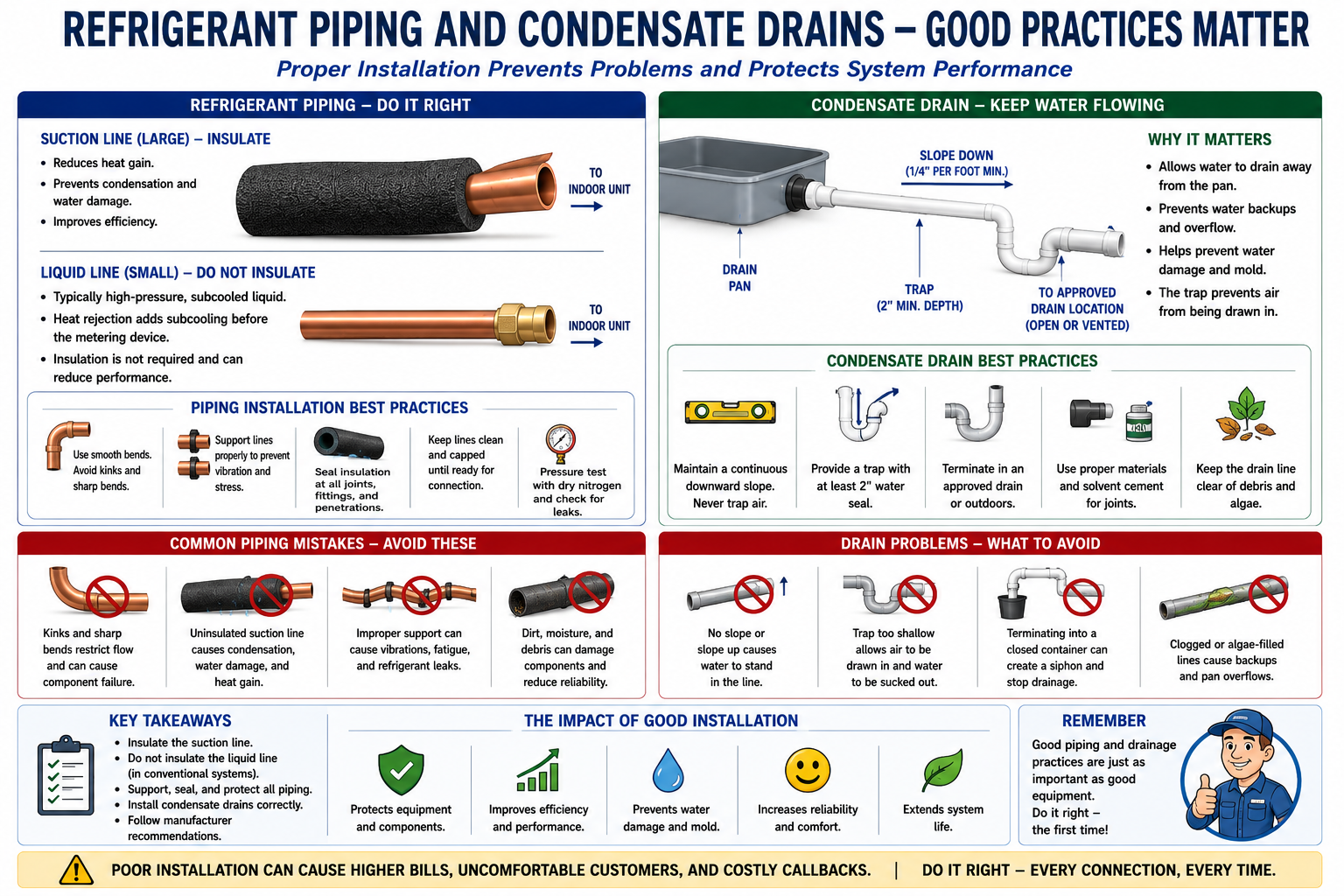
Ductless indoor units remove moisture from the air during cooling just like other evaporators. That condensed water must be removed through a properly installed drain system.
Maintain Drain Slope
Gravity drains require continuous downward slope without unintended rises or sags that can hold water.
Avoid Kinks
Flexible drain tubing should not be crushed or bent sharply enough to restrict water flow.
Follow Trap Requirements
Install traps or other condensate-drain provisions where required by the equipment design and manufacturer instructions.
Protect the Building
Drain failures can damage walls, ceilings, flooring, furnishings, and equipment even when the refrigeration system itself operates normally.
Do Not Coil Excess Tubing Without Checking the Manufacturer
Installers sometimes encounter factory line assemblies or line sets that are longer than the building route requires. Excess tubing should not automatically be coiled behind the outdoor unit or above the ceiling.
Maintain Minimum Bend Radius
Do not create tight coils that flatten or kink the refrigerant tubing.
Avoid Oil Pockets
Poorly arranged coils and low spots can create locations where oil collects.
Check Maximum and Minimum Length
Some equipment has minimum as well as maximum refrigerant piping requirements.
Follow Approved Routing
Use the manufacturer’s instructions when excess tubing must be accommodated.
Ductless Piping Still Requires Proper Mechanical Support
The refrigerant piping principles covered earlier in this subsection continue to apply to ductless systems.
Prevent Sagging
Support tubing so refrigerant and oil do not collect in unintended low areas.
Protect Insulation
Supports should not crush or tear insulation on either refrigerant pipe.
Prevent Abrasion
Piping should not rub against framing, sheet metal, masonry, roofing, or other surfaces.
Protect Outdoor Runs
Exterior line sets may require line-hide systems, covers, UV protection, or other mechanical protection.
Heat Pumps Reverse Refrigerant Flow
Most modern ductless air-conditioning systems are heat pumps. When operating in heating mode, the refrigeration cycle reverses so the indoor coil becomes the condenser and the outdoor coil becomes the evaporator.
Indoor Coil = Evaporator
The indoor coil absorbs heat from the building and the outdoor coil rejects that heat.
Indoor Coil = Condenser
The indoor coil rejects heat into the building while the outdoor coil absorbs heat from outside air.
A tube that carries one refrigerant state during cooling can carry a different state during heating. Always determine operating mode and refrigerant-flow direction before diagnosing the system.
Different Indoor Units Can Operate at Different Loads
In a multi-zone system, one indoor unit may require significant cooling while another requires very little. The system controller adjusts refrigerant distribution to satisfy the different zones.
High cooling load
Moderate cooling load
Low cooling load
Electronic expansion valves and compressor-speed control allow the system to change refrigerant flow rather than forcing every indoor unit to operate at the same capacity.
Multi-zone and VRF diagnostics require an understanding of individual indoor-unit demand, EEV positions, compressor capacity, system sensors, and manufacturer service data.
These Systems Depend Heavily on Installation Instructions
Pipe Diameters
Use the exact tubing sizes specified for the outdoor unit, branches, and indoor units.
Maximum Lengths
Check individual branch, combined total, and post-branch piping limits.
Vertical Separation
Confirm outdoor-to-indoor and indoor-to-indoor elevation limits where applicable.
Insulation
Use the required insulation thickness and coverage on each refrigerant pipe.
Refrigerant Charge
Calculate additional refrigerant using the manufacturer’s method for the complete piping network.
Branch Components
Install approved headers, branch joints, distribution boxes, or other components in the required orientation.
Two systems with similar capacities can have very different piping limitations. Always use the installation manual for the exact model and indoor-unit combination being installed.
Think Beyond “Liquid Line and Suction Line”
Many ductless and variable-capacity systems place electronic metering devices in the outdoor unit.
Refrigerant in the smaller connecting tube may already have passed through a metering device and therefore may not be conventional high-pressure liquid.
Refrigerant state must be determined from equipment design, metering-device location, operating mode, pressures, temperatures, and manufacturer information.
Inverter compressors and EEVs continually change refrigerant mass flow as equipment capacity changes.
Both refrigerant pipes are commonly insulated on ductless equipment and should remain insulated where the manufacturer requires.
Multi-zone systems can have separate limits for individual branch length, total combined piping length, and vertical separation.
Flare joints, refrigerant piping, insulation, supports, condensate drains, and building penetrations all require correct installation workmanship.
The equipment manufacturer’s instructions determine the approved piping sizes, lengths, insulation, refrigerant charge, branch components, and installation procedures.
Can You Explain Ductless Refrigerant Piping?
You should be able to answer these questions before continuing.
- Where is the metering device commonly located in a conventional split cooling system?
- Where may the EEV be located in a ductless system?
- Why might the smaller ductless refrigerant pipe not be a conventional liquid line?
- Why should tubing size alone not be used to determine refrigerant state?
- How does inverter compressor operation affect refrigerant mass flow?
- Why does refrigerant velocity change as system capacity changes?
- Why are both refrigerant pipes commonly insulated on ductless equipment?
- Why should conventional liquid-line insulation practices not automatically be applied to ductless systems?
- What types of piping-length limits can apply to a multi-zone installation?
- Why may additional refrigerant calculations be more complex on multi-zone systems?
- Why should flare connections be tightened to the manufacturer’s specified torque?
- What problems can result from poorly routed excess refrigerant tubing?
- Why does heat-pump operation make pipe names less reliable?
- Why can one pressure reading fail to describe the operating condition of an entire multi-zone system?
What You Should Have Learned
Ductless and variable-capacity refrigerant piping may operate differently from the conventional liquid-line and suction-line arrangement used in basic split systems.
When the EEV is located in the outdoor unit, refrigerant may undergo its pressure drop before traveling through the connecting tubing to the indoor unit.
Refrigerant state should be determined from system design and operating conditions rather than tubing diameter alone.
Variable-speed compressors and electronic expansion valves continually change refrigerant flow to match system load.
Both refrigerant pipes are commonly insulated on ductless equipment because refrigerant conditions can differ from conventional split-system piping.
Multi-zone systems may have separate limits for individual piping runs, total piping length, vertical separation, and branch-component locations.
Flare connections, tubing supports, insulation, condensate drains, and building penetrations are all important parts of a reliable ductless installation.
Manufacturer installation and service information is essential when designing, installing, charging, or diagnosing ductless and variable-capacity refrigerant piping.