Factory Refrigerant Charge and Line-Set Length
Many split air-conditioning and heat-pump systems leave the factory with refrigerant already stored in the outdoor unit. That factory charge is intended for a specific equipment combination and a specified amount of refrigerant piping.
A system described as factory charged or precharged is not automatically charged correctly for every installation. The technician must determine how much line-set length is included in the factory charge and follow the manufacturer’s instructions when the installed piping differs from that allowance.
What You Will Learn
By the end of this lesson you should be able to:
Explain what factory charged means.
Describe why an outdoor unit can contain refrigerant from the factory while still requiring charge adjustment during installation.
Identify the line length included in the factory charge.
Use the manufacturer’s installation instructions rather than assuming that every precharged system includes the same tubing length.
Determine actual installed line-set length.
Measure the tubing path rather than using only the straight-line distance between the indoor and outdoor equipment.
Explain additional refrigerant requirements.
Recognize that manufacturers may specify an additional refrigerant mass for each unit of tubing length beyond the factory allowance.
Recognize when refrigerant may need to be removed.
Understand that some manufacturers provide charge adjustments for line sets shorter than the factory-charge allowance or for specific equipment combinations.
Verify final refrigerant charge correctly.
Use the equipment manufacturer’s specified charging method rather than relying on pressure alone or attempting to clear a sight glass.
What Does “Factory Charged” Mean?
Many split systems are shipped with a specified quantity of refrigerant stored in the outdoor unit. During installation, the line set and indoor coil are connected, leak tested, evacuated, and then placed into communication with the refrigerant contained in the outdoor unit according to the manufacturer’s procedure.
The amount of refrigerant shipped in the outdoor unit is based on the manufacturer’s design assumptions. Line-set length, tubing size, indoor coil, equipment combination, and other installation factors can change the final required system charge.
The Factory Charge Usually Assumes a Specified Piping Length
The installation instructions identify the refrigerant-line length included in the factory charge. That included length is not universal and must be checked for the actual equipment being installed.
Covered by Factory Charge
The manufacturer specifies the amount of line set for which the factory refrigerant quantity is intended.
May Require Additional Refrigerant
If the installed tubing exceeds the included allowance, the manufacturer may specify additional refrigerant by mass for the extra length.
Some technicians remember a common line length from equipment they have installed previously. That value must not be transferred automatically to another manufacturer, model, capacity, refrigerant, or equipment combination.
Measure the Tubing Path, Not the Building Separation
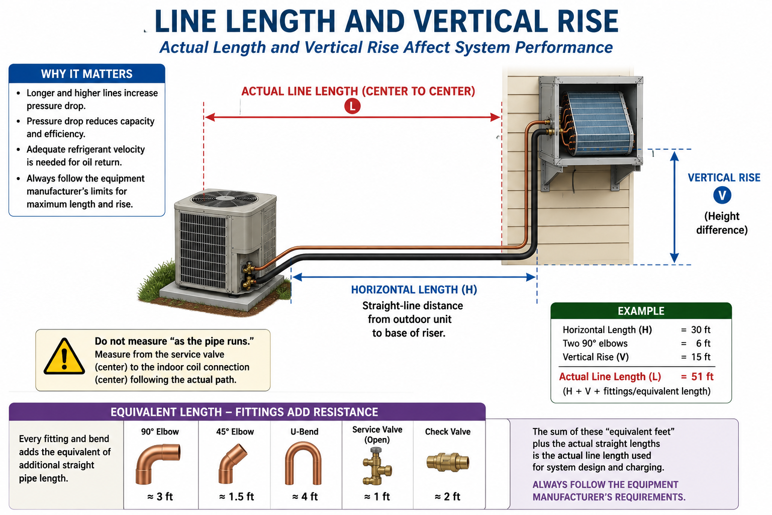
The actual refrigerant-line length includes the tubing path between the equipment. A system with indoor and outdoor units only 20 feet apart may contain considerably more than 20 feet of tubing after vertical runs, offsets, and routing around building structures are included.
Horizontal Runs
Include the actual horizontal tubing installed between equipment locations.
Vertical Runs
Include tubing traveling upward or downward between floors, rooftops, attics, or equipment elevations.
Offsets and Routing
Include tubing used to route around building features and reach equipment connections.
Manufacturer Calculation Method
Use the manufacturer’s method for determining whether actual length, equivalent length, or another defined measurement is used for charge adjustment.
Longer Line Sets Increase Refrigerant Volume
Additional tubing increases the internal volume of the refrigeration system. When installed line length exceeds the amount included in the factory charge, additional refrigerant may be required.
The refrigerant addition rate is typically expressed as a mass per unit of additional tubing length. The actual rate must come from the manufacturer’s instructions for the equipment.
Do not memorize one refrigerant addition rate and apply it to every split system. Refrigerant type, tubing size, equipment capacity, indoor coil, outdoor unit, and manufacturer design can all affect the required charge adjustment.
Follow the Manufacturer’s Published Values
The following example demonstrates the calculation method only. The numbers are hypothetical and are not universal charging values.
35 ft
15 ft
20 ft
0.6 oz/ft
12 oz additional refrigerant
The 15-foot allowance and 0.6-ounce-per-foot rate above exist only to demonstrate the arithmetic. Never use these values unless the actual equipment manufacturer specifies them for the equipment being serviced.
Refrigerant Volume Depends on More Than Length
A foot of large-diameter tubing contains more internal volume than a foot of small-diameter tubing. This is another reason additional refrigerant requirements cannot be reduced to one universal line-length rule.
Liquid-Line Diameter
Changes the refrigerant volume contained in the high-pressure liquid portion of the line set.
Suction-Line Diameter
Changes the internal system volume and also affects refrigerant velocity and pressure drop.
Equipment Capacity
Different equipment capacities may use different line sizes and refrigerant quantities.
Equipment Combination
The outdoor unit and indoor coil combination may affect the specified system charge.
Do Not Assume a Short Line Set Always Uses the Full Factory Charge
Some equipment manufacturers provide instructions for installations where the refrigerant line set is shorter than the length assumed by the factory charge.
Depending on the equipment design, the manufacturer may specify that refrigerant be removed, may specify no adjustment within a certain range, or may provide another procedure.
Do not think only about adding refrigerant for long lines. Read the complete manufacturer’s charging instructions and determine whether shorter line sets require any adjustment.
Charge Adjustment and Piping Design Are Related but Different
Vertical separation can affect refrigerant piping design even when the charge calculation is based primarily on total tubing length.
Total Refrigerant Quantity
Line length affects the volume of the refrigeration circuit and therefore can affect the required refrigerant charge.
Pressure Relationships
Elevation differences can affect liquid-line and suction-line operating conditions.
Oil Return
Vertical suction risers can require special attention to refrigerant velocity and compressor oil return.
Manufacturer Limits
Maximum total length and maximum vertical separation are often separate installation limits and both must be satisfied.
If an installation exceeds the manufacturer’s maximum vertical separation or piping design limits, adding more refrigerant does not make the piping arrangement acceptable.
Charge Adjustments Are Based on Refrigerant Mass
When the manufacturer specifies that a known quantity of refrigerant must be added or removed, that quantity should be measured by mass using an appropriate refrigerant scale.
Determine Required Adjustment
Calculate the additional or removed refrigerant using the manufacturer’s instructions.
Use a Refrigerant Scale
Measure the actual refrigerant mass transferred into or out of the system.
Record the Final Charge
Document the refrigerant quantity where required by manufacturer instructions, service records, or applicable code.
System pressure changes with refrigerant temperature, indoor load, outdoor temperature, airflow, compressor operation, and other conditions. A gauge pressure alone cannot tell the technician the exact mass of refrigerant in the system.
The Line-Length Calculation Is the Starting Point, Not Always the Final Check
After the specified refrigerant quantity has been installed, many systems require a final operating check using the manufacturer’s charging procedure.
Subcooling
Many systems with a TXV or EEV are verified using a manufacturer-specified subcooling target or charging procedure.
Superheat
Some fixed-metering systems use superheat as part of the specified charging method.
Weighed Charge
Some equipment and operating conditions require charging primarily or exclusively by refrigerant mass.
Manufacturer Procedure
The service manual determines the correct verification method, operating conditions, tolerances, and required measurements.
As covered in the previous lesson, bubbles or a clear sight glass do not establish correct system charge. Use the equipment manufacturer’s specified charging procedure.
Do Not Evaluate Charge Under Invalid Conditions
Charging procedures based on superheat, subcooling, pressures, or temperatures usually require the equipment to operate under specified indoor and outdoor conditions.
Indoor Airflow
Incorrect airflow changes evaporator load, suction pressure, superheat, and system capacity.
Outdoor Temperature
Condenser operating conditions affect head pressure, subcooling, and refrigerant distribution.
Indoor Load
Indoor temperature and humidity affect evaporator performance and refrigeration-system readings.
System Stabilization
The equipment should normally operate long enough for measurements to stabilize before final charge evaluation.
More Refrigerant Is Not Better
Adding refrigerant beyond the manufacturer’s required quantity can create an overcharged system.
Higher Condensing Pressure
Excess refrigerant can increase the amount of liquid stored in the condenser and raise high-side operating pressure.
Higher Subcooling
Subcooling may rise above the manufacturer’s target as excess liquid backs up in the condenser.
Reduced Efficiency
The compressor may operate against unnecessarily high condensing pressure.
Possible Compressor Stress
Severe overcharge or other abnormal refrigerant conditions can contribute to poor system operation and compressor problems.
Low suction pressure can result from low airflow, low evaporator load, a restriction, metering-device problems, compressor-capacity changes, and other causes. Diagnose the system before changing refrigerant charge.
Too Little Refrigerant Can Starve the Evaporator
Insufficient Liquid Supply
The condenser may not maintain an adequate supply of subcooled liquid to the metering device.
Higher Superheat
The evaporator can become underfed and the refrigerant may boil off too early in the coil.
Lower Capacity
Part of the evaporator may no longer be effectively used for boiling refrigerant and absorbing heat.
Possible Flash Gas
Insufficient liquid-line conditions can allow vapor to form before the intended metering device.
Do Not Apply Conventional Split-System Assumptions to Every Product
Some ductless and other equipment may use factory-precharged outdoor units, factory-prepared line assemblies, flare connections, specialized piping procedures, or other charging methods.
The refrigerant quantity may depend on total piping length, number of indoor units, branch components, equipment combination, or other manufacturer-specific factors.
Whether the system is a conventional split system or a ductless multi-zone system, determine the installed piping configuration and then use the manufacturer’s published refrigerant-charge requirements for that exact equipment.
Determine Charge Systematically
Identify the exact indoor and outdoor equipment combination and refrigerant.
Determine the line-set sizes, actual installed length, and vertical separation.
Read the manufacturer’s stated factory charge and the line-set length included in that charge.
Determine whether the installed piping requires refrigerant to be added or removed.
Calculate the required adjustment using the manufacturer’s published refrigerant mass per unit length or other specified procedure.
Use a refrigerant scale to measure the specified refrigerant quantity.
Operate the system under the conditions required for final charge verification.
Verify the final charge using the manufacturer’s specified superheat, subcooling, weighed-charge, or other approved procedure.
Can You Explain Factory Charge and Line-Set Length?
You should be able to answer these questions before continuing.
- What does it mean when an outdoor unit is factory charged?
- Does factory charged mean that no refrigerant adjustment can ever be required?
- Where do you find the line-set length included in the factory charge?
- Why should straight-line equipment separation not be used automatically as the line-set length?
- Why can a longer line set require additional refrigerant?
- Is there one universal ounces-per-foot refrigerant addition rate?
- Why does tubing diameter affect refrigerant quantity?
- Can a line set shorter than the factory allowance ever require a charge adjustment?
- Why are maximum vertical separation and refrigerant charge two different installation concerns?
- What tool should be used when adding a specified mass of refrigerant?
- Why can system pressure alone not determine the exact refrigerant charge?
- What charging methods might a manufacturer specify for final verification?
- Why should a sight glass not be used as the final charging standard?
- Why must airflow and operating conditions be correct before evaluating charge?
What You Should Have Learned
A factory-charged outdoor unit contains a specified refrigerant quantity based on the equipment manufacturer’s design and installation assumptions.
The factory refrigerant charge normally corresponds to a specified equipment combination and an included refrigerant-line length.
The actual installed tubing path must be determined rather than using only the straight-line distance between the indoor and outdoor equipment.
Line sets exceeding the factory-charge allowance may require additional refrigerant according to a manufacturer-specified mass-per-length value or other procedure.
There is no universal refrigerant addition rate that can be applied to all equipment.
Some manufacturers also provide instructions for charge adjustment when installed piping is shorter than the line length assumed by the factory charge.
Known refrigerant additions or removals should be measured by mass with a refrigerant scale.
The final system charge must be verified using the equipment manufacturer’s specified procedure and valid operating conditions.