Filter-Driers and Moisture-Indicating Sight Glasses
Filter-driers and moisture-indicating sight glasses are installed in refrigerant piping to protect and monitor the refrigeration system. The filter-drier removes moisture, acids, particles, and other contaminants, while the moisture indicator provides information about system dryness.
These components are useful service tools, but they must be interpreted correctly. A sight glass is not a refrigerant charging tool, and bubbles in the sight glass do not automatically prove that a system is undercharged.
What You Will Learn
By the end of this lesson you should be able to:
Explain the purpose of a filter-drier.
Describe how the filter-drier protects the refrigeration system from moisture, acids, debris, and other contaminants.
Identify proper filter-drier location and flow direction.
Recognize why liquid-line filter-driers are installed in the refrigerant path ahead of the metering device and why directional models must be installed correctly.
Explain the purpose of a moisture-indicating sight glass.
Describe how the indicator provides information about moisture condition without using it as a refrigerant charging method.
Explain why bubbles do not prove undercharge.
Recognize that bubbles may appear for several reasons and should not be used alone to determine refrigerant charge.
Diagnose a restricted filter-drier.
Use inlet and outlet liquid-line temperatures to identify a meaningful temperature difference across the component.
Explain why a restricted filter-drier acts like an unintended metering device.
Connect the pressure drop through a restriction to cooling, flashing, frost, and condensation downstream of the drier.
Protecting the Refrigeration System
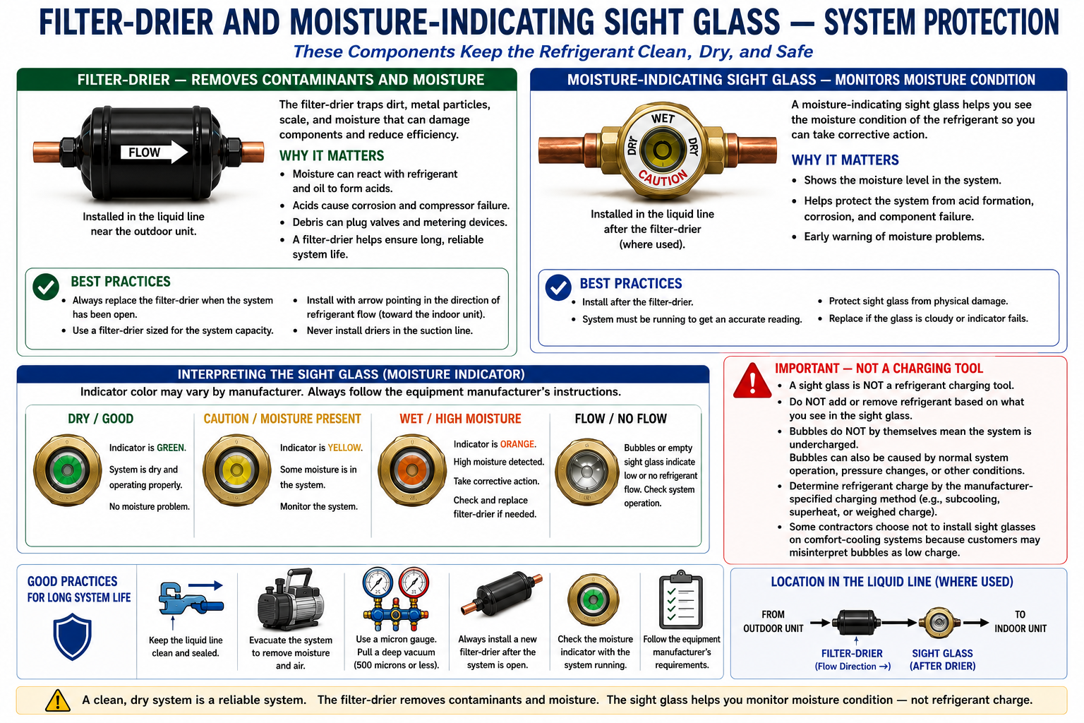
A refrigeration system should contain only the correct refrigerant and lubricant. Moisture, acids, dirt, copper oxide, metal particles, and other contaminants can damage compressors, restrict metering devices, and create long-term reliability problems.
Remove Moisture
Desiccant inside the filter-drier absorbs moisture from the circulating refrigerant.
Remove Particles
The filtering material captures solid contaminants before they can reach small passages and moving components.
Reduce Acid Contamination
Properly selected filter-driers can help remove harmful acidic contaminants from the refrigeration circuit.
Protect the Metering Device
Keeping debris out of capillary tubes, fixed orifices, TXVs, AEVs, and EEVs helps prevent restrictions and malfunction.
Contamination control is not only about immediate operation. Moisture and debris can create problems months or years after installation if they remain inside the sealed refrigeration circuit.
Why the Filter-Drier Is Commonly Installed Before the Metering Device
In a conventional split system, the liquid-line filter-drier is normally installed in the high-pressure liquid line ahead of the metering device.
This location allows the filter-drier to protect the metering device and evaporator from contamination carried through the liquid line.
Many filter-driers are directional. If the shell is marked with a refrigerant-flow arrow, install the drier so the arrow matches the actual refrigerant-flow direction required by the system and operating mode.
What the Sight Glass Is For
A moisture-indicating sight glass provides a visible indication of moisture condition in the refrigerant circuit. The indicator material changes color according to the moisture level for the refrigerant and indicator design.
Indicator Shows the Dry Color
The indicator color corresponds to the manufacturer’s acceptable moisture range.
Indicator Changes Color
The indicator shows that excessive moisture may be present in the refrigeration system.
Do not assume that every moisture indicator uses the same colors. Read the legend printed on the sight glass or use the component manufacturer’s information.
Do Not Charge a System Until the Sight Glass Clears
A sight glass is not a refrigerant charging tool. Refrigerant charge must be determined using the method specified by the equipment manufacturer.
Historically, some technicians associated a clear liquid-line sight glass with correct refrigerant charge. That is not a reliable universal charging method.
Bubbles Can Have Multiple Causes
Bubbles can appear because of pressure drop, low subcooling, changing load, startup conditions, flashing in the liquid line, or other operating conditions.
Clear Does Not Prove Correct Charge
A clear sight glass does not prove that the system contains the manufacturer’s required refrigerant charge.
Use the Manufacturer’s Charging Method
The correct procedure may involve weighed charge, subcooling, superheat, or another specified method depending on the equipment.
Do Not Add Refrigerant Just to Remove Bubbles
Adding refrigerant solely to clear the sight glass can result in an overcharged system.
Visible bubbles can be misunderstood by building owners or customers as proof that the system is low on refrigerant. For that reason, some contractors do not routinely install sight glasses where they are not required by the equipment design or service strategy.
A Filter-Drier Can Become a Refrigerant Restriction
As a filter-drier collects contamination, or if the desiccant or internal material becomes damaged, refrigerant flow through the component can become restricted.
A restricted filter-drier produces an unwanted pressure drop in the liquid line.
A severe filter-drier restriction creates a pressure drop before the intended metering device. If the pressure falls enough, refrigerant may begin to flash into vapor at or downstream of the restriction.
Measure Both Sides of the Filter-Drier
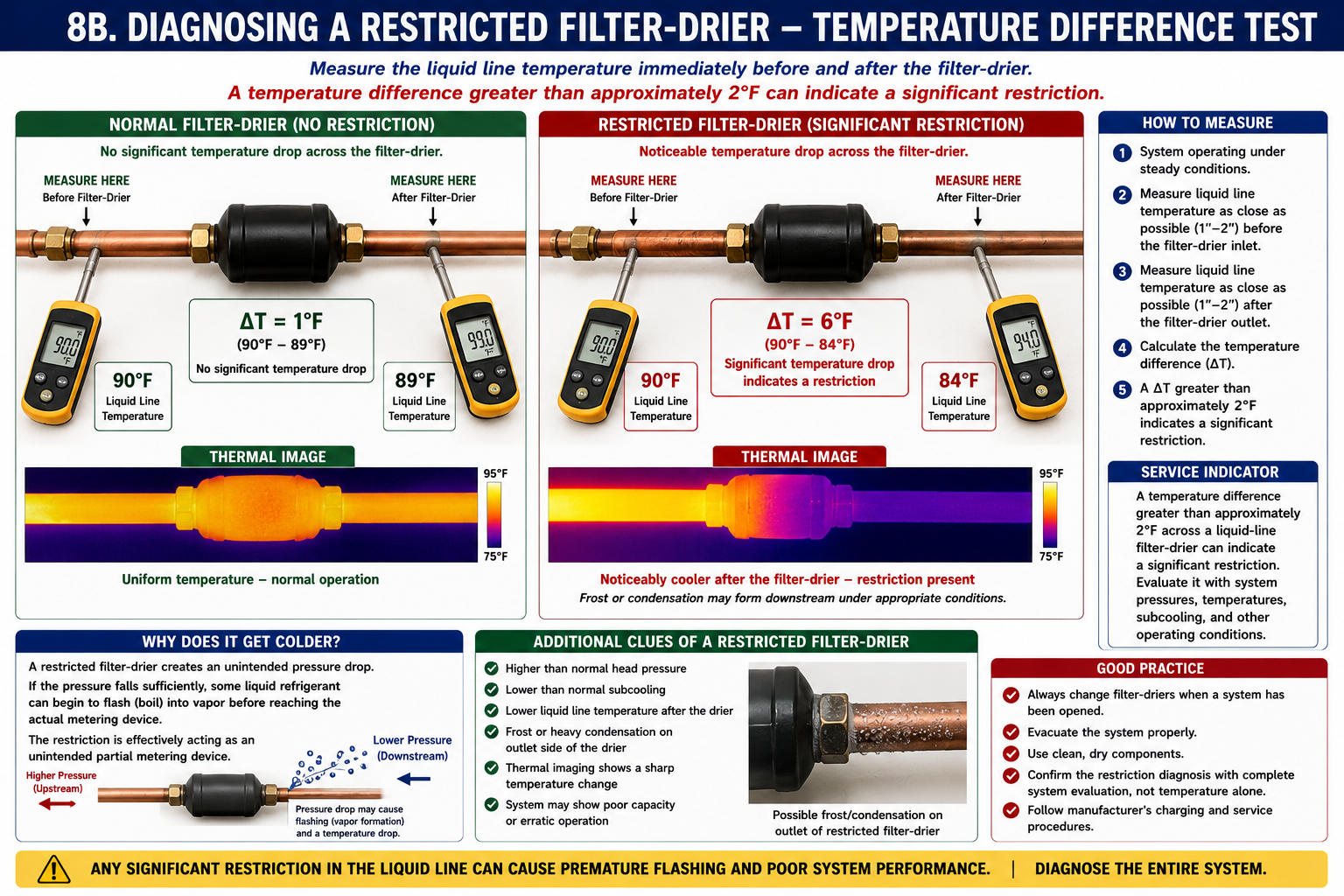
A useful field check is to measure the liquid-line temperature immediately before and immediately after the filter-drier while the system is operating under stable conditions.
Measure the Inlet
Measure liquid-line temperature close to the filter-drier inlet.
Measure the Outlet
Measure liquid-line temperature close to the filter-drier outlet.
Calculate the Difference
Subtract the colder temperature from the warmer temperature to determine the temperature difference across the component.
Little temperature difference indicates little measurable pressure drop across the drier under these example conditions.
A significant temperature difference supports the diagnosis of an unwanted restriction.
A temperature difference greater than approximately 2°F across a liquid-line filter-drier is a strong indication that the drier is significantly restricted and should be investigated.
Confirm the diagnosis with the rest of the refrigeration-system measurements and operating conditions. Sensor accuracy, changing load, ambient conditions, and measurement technique can affect small temperature differences.
Pressure Drop Changes Refrigerant Saturation Conditions
The temperature change across a restricted filter-drier is not caused merely by the metal shell becoming dirty. The refrigeration process explains what is happening.
If the pressure drop becomes large enough, part of the liquid refrigerant can begin flashing into vapor before the refrigerant reaches the intended metering device.
The intended metering device is supposed to create the major pressure drop into the evaporator. A restricted filter-drier creates an additional unwanted pressure drop upstream of that device.
Frost or Condensation Can Appear
If the pressure and temperature drop across the filter-drier becomes large enough, the outlet side of the component or the downstream liquid line may become cold enough to condense moisture from the surrounding air.
Temperature Difference
The outlet side measures noticeably colder than the inlet side.
Condensation
Moisture can form on the colder portion of the drier or downstream tubing when its temperature falls below the surrounding-air dew point.
Frost
Under sufficiently cold conditions, frost can form at or immediately downstream of the restriction.
Starved Evaporator
The restriction can reduce the amount of liquid refrigerant reaching the actual metering device, resulting in evaporator underfeeding.
A cold or frosted location indicates that a significant pressure drop may be occurring in that area. Confirm where the restriction actually exists before replacing components.
A Restriction Can Be Very Obvious on a Thermal Camera
Thermal imaging can make the temperature transition across a restricted filter-drier easy to see. A normal drier should show relatively little temperature change from one end to the other, while a severely restricted drier may show a sharp thermal transition.
Normal Drier
The inlet, shell, and outlet remain relatively similar in temperature.
Restricted Drier
The outlet side and downstream liquid line appear significantly colder than the inlet side.
A thermal camera makes temperature differences easier to locate, but the technician should still verify the condition with contact temperature measurements and normal refrigeration-system diagnostics.
What Else Can a Restricted Filter-Drier Cause?
Reduced Liquid Flow
Less refrigerant reaches the metering device and evaporator.
High Evaporator Superheat
The evaporator can become starved because insufficient refrigerant is being supplied.
Low Suction Pressure
A starved evaporator can result in lower-than-expected suction pressure.
Loss of Capacity
Reduced refrigerant flow limits the amount of heat the evaporator can absorb.
A restricted filter-drier can create symptoms that resemble a restricted or underfeeding metering device. Always verify liquid supply and check for upstream restrictions before condemning a TXV or EEV.
Filter-Driers Are Service Components
A filter-drier that is significantly restricted, contaminated, damaged, or otherwise unable to perform its intended function should be replaced using procedures appropriate for the refrigeration system.
System Opened for Major Repair
Manufacturer procedures commonly require replacement when the sealed refrigeration circuit has been opened for certain repairs.
Moisture or Contamination
A drier may be replaced as part of correcting moisture, acid, debris, or compressor-failure contamination.
Measured Restriction
A significant temperature drop and supporting system symptoms can indicate that the drier is restricting refrigerant flow.
Manufacturer Requirement
Always follow the equipment and filter-drier manufacturer’s service recommendations for replacement and selection.
Use the Correct Component for the System
Filter-driers are selected according to refrigerant, system capacity, line size, pressure rating, flow direction, application, and contamination-removal requirements.
Refrigerant Compatibility
The filter-drier must be approved for the refrigerant and lubricant used in the system.
Pressure Rating
The shell and connections must be suitable for the maximum pressures of the refrigeration system.
Line Size
Connections must match the refrigerant piping and provide adequate flow capacity.
Flow Direction
Directional and heat-pump applications require the correct filter-drier design and orientation.
Keep the Refrigeration Circuit Clean and Dry
Prevent Contamination
Keep tubing capped or sealed during installation so moisture and debris do not enter the refrigeration circuit.
Flow Nitrogen While Brazing
Prevent copper oxide scale from forming inside the tubing. This will be covered in detail later in the subsection.
Evacuate Properly
Remove air and moisture from the system according to the manufacturer’s procedures before releasing or charging refrigerant.
Do Not Use the Sight Glass to Charge
Use the manufacturer’s specified refrigerant-charging method and treat the sight glass primarily as a moisture/system-condition indicator.
Filter-Driers and Sight Glasses Serve Different Purposes
The filter-drier removes moisture, acids, particles, and other contaminants from the refrigerant circuit.
A liquid-line filter-drier helps protect the metering device from contamination.
A moisture-indicating sight glass provides information about system moisture condition.
The sight glass is not a refrigerant charging tool, and bubbles alone do not prove that the system is undercharged.
A restricted filter-drier creates an unwanted liquid-line pressure drop and begins acting like an unintended partial metering device.
A temperature difference greater than approximately 2°F across a liquid-line filter-drier is a strong indication of a significant restriction.
Severe restrictions can produce condensation, frost, visible thermal differences, and evaporator starvation.
Filter-drier diagnosis should be confirmed with the complete set of refrigeration-system measurements and manufacturer information.
Can You Explain Filter-Driers and Sight Glasses?
You should be able to answer these questions before continuing.
- What contaminants does a filter-drier remove from a refrigeration system?
- Why is a liquid-line filter-drier commonly installed ahead of the metering device?
- Why is filter-drier flow direction important?
- What is the primary purpose of a moisture-indicating sight glass?
- Should a system be charged until all bubbles disappear from the sight glass?
- Why do bubbles in a sight glass not automatically prove an undercharged system?
- What charging method should be used instead of the sight glass?
- What happens to pressure across a restricted filter-drier?
- Why can the outlet side of a restricted filter-drier become colder?
- What temperature difference across a liquid-line filter-drier is a strong indication of restriction?
- Why can condensation or frost form downstream of a severe restriction?
- How can a thermal camera help diagnose a restricted filter-drier?
- Why can a restricted filter-drier be mistaken for a bad TXV or other metering device?
- Why should the diagnosis be confirmed with additional system measurements?
What You Should Have Learned
Filter-driers protect refrigeration systems by removing moisture, acids, particles, and other contaminants.
Liquid-line filter-driers protect metering devices by cleaning and drying the refrigerant before it reaches the intended restriction.
Moisture-indicating sight glasses are used primarily to indicate system moisture condition.
A sight glass is not a refrigerant charging tool, and bubbles should not be used alone to determine refrigerant charge.
A restricted filter-drier creates an unwanted pressure drop in the liquid line and can act as a partial metering device.
A temperature difference greater than approximately 2°F across a liquid-line filter-drier is a strong indication of a significant restriction.
A severe restriction can cause the outlet side to become cold enough for condensation or frost and can starve the evaporator.
Temperature measurements, thermal imaging, pressures, superheat, subcooling, and other operating information should be considered together before replacing a filter-drier or metering device.