Bends, Fittings, and Equivalent Length
Refrigerant tubing rarely travels in a perfectly straight line between the indoor and outdoor equipment. Every bend, elbow, fitting, valve, and change in direction adds resistance to refrigerant flow.
Good refrigerant piping design minimizes unnecessary restrictions, uses smooth bends where practical, avoids kinking the tubing, and accounts for the added resistance of fittings when the equipment manufacturer requires equivalent-length calculations.
What You Will Learn
By the end of this lesson you should be able to:
Explain why bends and fittings create pressure drop.
Describe how changes in refrigerant direction and flow path add resistance to the tubing system.
Compare tight bends with sweeping bends.
Explain why smooth, long-radius bends generally create less resistance than tight-radius fittings and abrupt changes in direction.
Explain equivalent length.
Describe how the resistance of fittings can be represented as an additional length of straight tubing.
Recognize the importance of tubing workmanship.
Identify kinks, flattened tubing, unnecessary fittings, and poor routing as potential sources of excessive pressure drop.
Connect fittings to oil return.
Recognize how excessive restrictions and poor routing can affect refrigerant velocity and oil movement through the system.
Use manufacturer piping requirements.
Understand that fitting allowances and maximum equivalent lengths must come from the equipment manufacturer’s installation information.
Every Change in Direction Adds Resistance
As refrigerant moves through tubing, friction between the refrigerant and the inside wall of the copper creates pressure drop. A straight tube produces some resistance, but bends and fittings create additional turbulence and directional change.
Some pressure drop is unavoidable whenever refrigerant flows through tubing. The goal is to keep pressure drop within the range allowed by the equipment design so system capacity, efficiency, and oil return remain acceptable.
Smoother Turns Usually Create Less Resistance
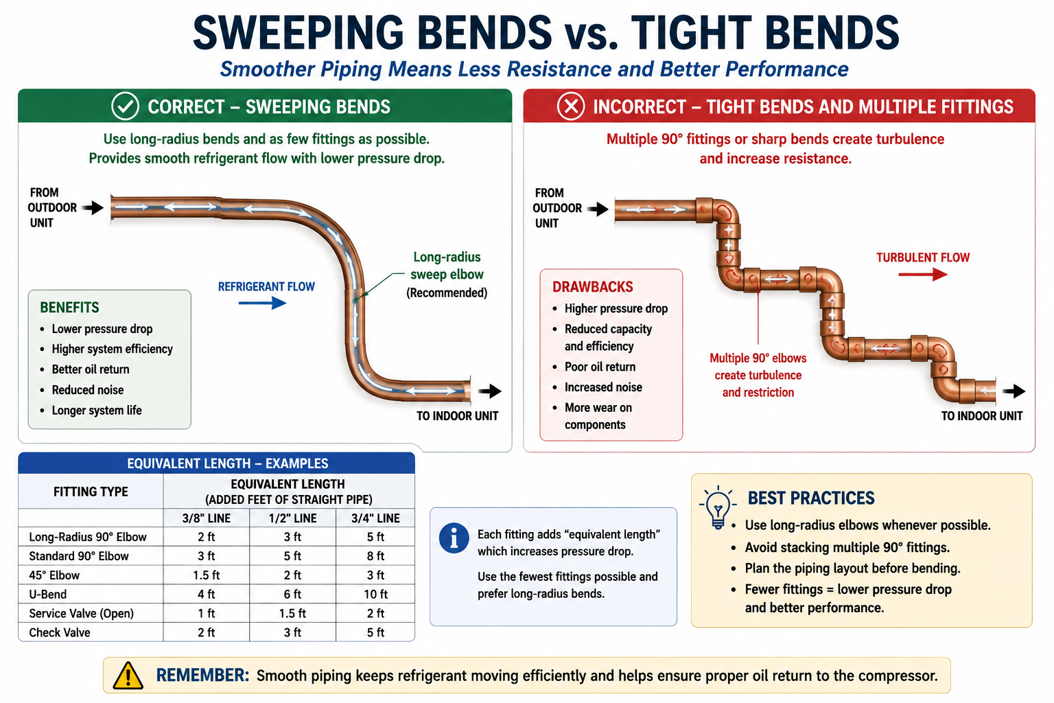
Sweeping Bend
A gradual bend changes refrigerant direction smoothly and generally creates less turbulence and pressure drop.
Tight-Radius Bend or Fitting
A sharp turn forces the refrigerant to change direction more abruptly and usually creates greater resistance.
Every fitting adds another potential source of pressure drop and another joint that must be installed correctly and remain leak-free. Good routing minimizes unnecessary elbows and direction changes.
Bend the Tube Without Damaging It
Soft copper ACR tubing can often be bent in the field, but the bend must maintain the internal cross-sectional area of the tube.
Proper Bend
The tubing remains round and smooth through the turn, with no flattening or collapse of the internal passage.
Flattened Bend
A flattened tube reduces the effective internal area and can increase pressure drop.
Kinked Tube
A kink creates a severe restriction and can act like an unintended partial metering device.
Use an appropriate tubing bender or other approved method for the tubing size and material. Do not force a bend tighter than the tubing can tolerate without distortion.
A Fitting Can Be Treated Like Additional Straight Tubing
Equivalent length is a way of representing the resistance of a fitting as an additional length of straight tubing.
The additional straight-tubing length that would create approximately the same resistance as a particular fitting or component.
A tight elbow, long-radius elbow, service valve, check valve, solenoid valve, or other component can each create a different amount of resistance. The equivalent-length value can also change with tubing size.
Two Installations Can Have the Same Physical Distance but Different Resistance
Direct Routing
A short, direct tubing path with gradual bends and few fittings has relatively low added resistance.
Complex Routing
The same building separation with many elbows and direction changes can have significantly greater equivalent length.
Good line-set routing generally uses the shortest practical path while maintaining serviceability, proper support, protection from damage, and compliance with manufacturer requirements.
Restrictions on the Suction Side Can Reduce System Performance
The suction line carries low-pressure refrigerant vapor back to the compressor. Excessive pressure drop through this line reduces the pressure available at the compressor inlet compared with the pressure leaving the evaporator.
Lower Compressor Inlet Pressure
Excessive suction-line restriction increases the pressure difference between the evaporator and compressor inlet.
Reduced Refrigerant Density
Lower suction pressure can reduce vapor density entering the compressor and affect compressor mass flow.
Capacity Loss
Excessive piping pressure drop can reduce the useful refrigeration capacity available at the evaporator.
Efficiency Loss
The compressor may have to operate across a greater effective pressure ratio.
Too Much Restriction Can Cause Problems Before the Metering Device
The liquid line should deliver a reliable supply of high-pressure liquid refrigerant to the intended metering device.
Excessive resistance from long tubing, too many fittings, damaged tubing, or another restriction can reduce liquid pressure before the refrigerant reaches the metering device.
If the pressure drop is large enough, some refrigerant can begin flashing into vapor before it reaches the intended metering device. Later in this subsection we will use this principle to diagnose restricted filter-driers.
Good Routing Helps Oil Keep Moving
Oil return depends on refrigerant velocity and the physical path through the piping. Unnecessary low spots, excessive fittings, and poor routing can make it more difficult for circulating oil to return to the compressor.
Smooth Route
Gradual bends, proper supports, and no unnecessary low areas help refrigerant vapor continue carrying oil toward the compressor.
Poor Route
Multiple abrupt bends, sagging sections, or unnecessary traps can create locations where oil accumulates.
Reducing pressure drop is important, but the piping must also maintain enough refrigerant velocity for oil return. Correct tubing size and routing must satisfy both requirements.
Use the Method That Produces a Reliable Refrigerant Path
Refrigerant piping may use field-formed bends, manufactured fittings, or a combination of both. Neither method is automatically correct in every situation.
Field-Formed Bend
Can reduce the number of brazed joints and provide a smooth turn when the tubing can be bent without flattening or kinking.
Manufactured Fitting
Can provide a controlled change in direction where field bending is impractical, especially with larger or harder tubing.
A smooth manufactured elbow is better than a field bend that has been flattened, kinked, or damaged. The goal is a clean, unrestricted, leak-free refrigerant path.
Every Joint Is Another Installation Point
Fittings do more than add flow resistance. They also increase the number of joints in the refrigerant piping.
More Brazed Joints
Each fitting normally creates additional joints that must be brazed correctly.
More Leak Opportunities
Every joint must remain leak-free throughout system operation and thermal cycling.
More Internal Heating During Installation
Every brazed connection exposes the inside of the copper tubing to high temperature unless proper brazing practices are used.
More Installation Time
Unnecessary fittings increase labor, materials, pressure testing, and inspection points.
A direct tubing route with properly formed bends can reduce both equivalent length and the number of potential leak points.
Use the Piping Tables for the Actual Equipment
Manufacturers may specify maximum actual line length, maximum equivalent length, fitting allowances, vertical separation, required tubing diameter, and special piping provisions.
Maximum Actual Length
Limits the physical refrigerant tubing run between the equipment components.
Maximum Equivalent Length
Accounts for the added resistance of fittings and accessories where specified.
Tubing Size
Determines the relationship between refrigerant velocity and pressure drop.
Vertical Separation
Can create additional requirements for oil return and refrigerant piping configuration.
Do not assume that every 90-degree elbow adds the same number of feet to every refrigerant system. Use the manufacturer’s values or approved piping-design information for the tubing size and fitting type being installed.
Good Refrigerant Piping Should Be Simple and Deliberate
Preferred Installation
Direct route, correct tubing size, smooth bends, few unnecessary fittings, proper support, no kinks, no unintended low spots, and easy access for service.
Poor Installation
Multiple unnecessary elbows, sharp direction changes, crushed tubing, unsupported runs, accidental traps, excessive joints, and routing that exceeds manufacturer limits.
Follow the Resistance Through the Line Set
Refrigerant experiences friction as it flows through straight tubing.
Bends, elbows, valves, and fittings add resistance and additional pressure drop.
Sweeping bends generally create less resistance than tight-radius changes in direction.
Kinked or flattened tubing reduces internal flow area and can create a serious restriction.
Equivalent length represents fitting resistance as an additional length of straight tubing.
Excessive suction-line pressure drop can reduce system capacity and efficiency.
Excessive liquid-line pressure drop can reduce the liquid pressure available at the metering device and may contribute to premature flashing.
Manufacturer piping requirements determine allowable tubing lengths, equivalent lengths, fitting allowances, and routing limitations.
Can You Explain Bends, Fittings, and Equivalent Length?
You should be able to answer these questions before continuing.
- Why does refrigerant experience pressure drop as it moves through tubing?
- Why do bends and fittings create additional resistance?
- Why is a sweeping bend generally preferred over a tight bend?
- What happens if copper tubing becomes flattened during bending?
- Why is a kinked refrigerant line a serious problem?
- What is equivalent length?
- Why can two installations with the same straight-line distance have different equivalent lengths?
- How can excessive suction-line pressure drop affect system operation?
- How can excessive liquid-line pressure drop affect refrigerant arriving at the metering device?
- Why should unnecessary fittings be avoided?
- What additional installation concern comes with every fitting and brazed joint?
- Why should generic fitting-equivalent-length values not be applied to every system?
- How can poor piping routing affect oil return?
- Where should the technician obtain the allowable line-length and fitting information for the equipment?
What You Should Have Learned
Straight tubing creates frictional pressure drop, while bends and fittings add additional resistance and turbulence.
Sweeping bends generally create less flow resistance than abrupt tight-radius changes in direction.
Field bends must remain round and unrestricted; flattened or kinked tubing can create serious refrigerant restrictions.
Equivalent length represents the resistance of fittings and components as an additional length of straight tubing.
Excessive suction-line pressure drop can reduce refrigeration capacity and efficiency.
Excessive liquid-line pressure drop can reduce pressure at the metering device and may allow refrigerant to begin flashing before the intended restriction.
Unnecessary fittings increase both refrigerant-flow resistance and the number of joints that must remain leak-free.
Manufacturer installation information determines the acceptable actual length, equivalent length, fittings, tubing size, and piping arrangement for the system.