Condensate Management
When an evaporator coil operates below the dew-point temperature of the air, moisture condenses on the coil surface and must be collected and removed from the equipment.
Proper condensate management depends on more than simply connecting a drain pipe. The technician must understand the drain pan, piping slope, equipment pressure relationship, trap requirements, venting, air breaks, and the possibility of creating an unintended double trap.
A condensate system that is installed incorrectly can cause poor drainage, water overflow, equipment damage, microbial growth, and indoor-air-quality problems.
What You Will Learn
By the end of this lesson you should be able to:
Describe how moisture in the air condenses on an evaporator surface that is below the dew-point temperature.
Describe how the pan collects water from the evaporator and directs it toward the drain connection.
Determine whether the evaporator is on the discharge side or inlet side of the blower.
Recognize why a negative-pressure evaporator drain requires a trap while a typical positive-pressure evaporator drain does not.
Recognize how proper drain piping prevents air locking and avoids unintended double traps.
Identify clogged drains, incorrect slope, dry traps, double traps, pan problems, and drain piping installed against the equipment pressure relationship.
Why Does Condensate Form?
Air normally contains water vapor. When warm, humid air passes across an evaporator coil whose surface temperature is below the dew-point temperature of the air, some of that water vapor changes into liquid water.
This moisture collects on the fins and tubing and flows downward under gravity.
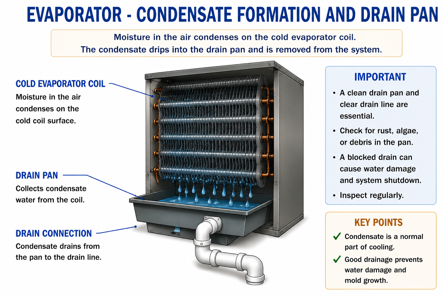
Water forming on an air-conditioning evaporator is normally evidence that the coil is removing latent heat and moisture from the air.
The problem begins when that water is not collected and drained correctly.
Follow the Condensate
Moisture Condenses on the Coil
Water vapor changes into liquid water on the cold evaporator surface.
Water Flows Into the Drain Pan
Gravity carries the condensate down the coil surface and into the pan below the evaporator.
The Pan Directs Water to the Outlet
The pan is shaped and installed so water can move toward the condensate drain connection.
Drain Piping Carries Water Away
The condensate piping transports the water to an approved disposal point.
The Condensate Drain Pan
The drain pan is the first part of the condensate-removal system after water leaves the evaporator surface.
The pan must collect water from the entire coil and direct it toward the intended drain opening.
Primary Drain Pan
The primary drain pan is part of the evaporator assembly and collects condensate during normal operation.
Drain Connection
The pan outlet connects to the condensate piping that removes water from the equipment.
The Pan Must Match the Equipment Orientation
An evaporator approved for multiple orientations may use different drain openings or pan arrangements depending on whether the unit is installed upflow, downflow, or horizontal.
The equipment manufacturer’s approved drain connections and orientation must be followed.
Condensate Piping Must Drain by Gravity
Most conventional condensate drain systems depend on gravity to move water away from the evaporator.
The drain line must therefore maintain continuous fall toward the disposal point unless the system design specifically uses a condensate pump or another approved method.
Proper Slope
Water continually moves away from the equipment without creating low points where condensate can collect.
Poor Slope
Sags, reverse pitch, and low spots can retain water and contribute to slow drainage, biological growth, and blockage.
If the drain depends on gravity, the piping must provide an uninterrupted path downhill.
Positive- and Negative-Pressure Condensate Drains
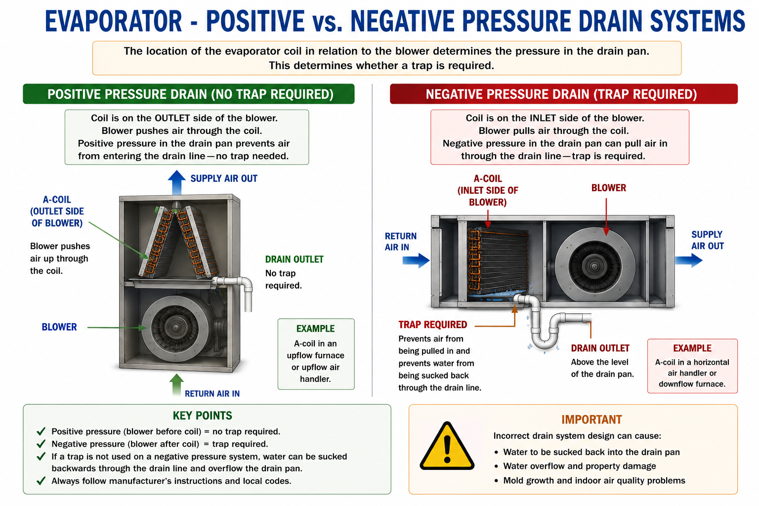
The location of the evaporator relative to the blower determines the pressure inside the cabinet at the drain pan.
Positive Pressure
The evaporator is on the discharge side of the blower. The blower pushes air through the coil and the drain pan operates above surrounding atmospheric pressure.
Negative Pressure
The evaporator is on the inlet side of the blower. The blower pulls air through the coil and the drain pan operates below surrounding atmospheric pressure.
Positive-Pressure Drain Systems
A typical upflow split system with an A-coil installed above the blower places the evaporator on the blower’s discharge side.
Air pressure inside the coil cabinet is greater than the surrounding atmospheric pressure.
Raises the air pressure.
Air is pushed through the coil.
Cabinet pressure assists rather than opposes water leaving the drain connection.
A condensate trap is normally not required simply for drainage on a positive-pressure evaporator system.
Do not add a trap to a positive-pressure drain unless the equipment manufacturer’s instructions or applicable local requirements call for one.
Negative-Pressure Drain Systems
When the evaporator is located on the inlet side of the blower, the blower pulls air through the coil.
This creates negative pressure inside the evaporator cabinet and drain pan.
If the drain connection is left open without a trap, the blower can pull air backward through the condensate drain line.
The Blower Runs
The blower pulls air through the evaporator coil.
Negative Pressure Develops at the Drain Pan
The pressure inside the evaporator cabinet falls below the surrounding atmospheric pressure.
Air Tries to Enter Through an Untrapped Drain
Blower suction can pull air backward through the drain piping.
Drainage Is Disrupted
The inward airflow can oppose gravity drainage and can pull condensate backward or prevent it from leaving the pan correctly.
Negative Pressure Requires a Trap
A properly designed condensate trap provides a water seal between the negative-pressure evaporator cabinet and the surrounding atmosphere.
Two Common Examples
Upflow Furnace With A-Coil Above the Blower
The blower pushes air through the evaporator.
Positive-pressure drain — trap normally not required.
Horizontal Air Handler With Coil Before the Blower
The blower pulls air through the evaporator.
Negative-pressure drain — trap required.
The Condensate Trap
A trap is a section of drain piping designed to retain enough water to create a seal between the equipment cabinet and the surrounding atmosphere.
On a negative-pressure system, the water seal prevents the blower from using the condensate drain as an unwanted air inlet.
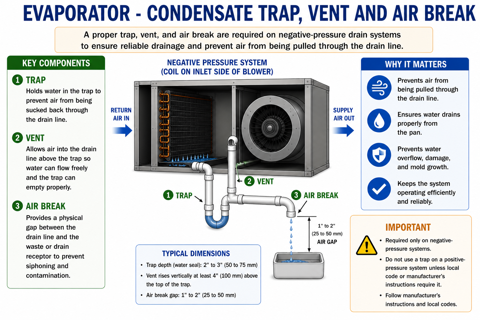
The trap dimensions must be appropriate for the negative pressure developed by the equipment. A trap that is too shallow can lose its water seal or allow air to be pulled through the drain.
Use the equipment manufacturer’s trap dimensions and installation instructions.
What Does the Trap Actually Do?
Water Remains in the Trap
The trap retains a standing column of condensate.
The Water Forms a Pressure Seal
The water prevents outside air from being freely pulled through the drain into the negative-pressure cabinet.
New Condensate Pushes Water Through the Trap
As additional condensate enters the drain, water can flow through the trap and continue toward the disposal point.
Why Is a Vent Used?
A properly located vent allows the downstream side of the condensate drain to communicate with atmospheric pressure.
This helps prevent pressure effects in the downstream piping from interfering with gravity drainage.
Vent Placement Matters
A vent installed in the wrong location can defeat the purpose of the trap by allowing air to bypass the water seal.
The vent belongs in the location specified for the particular drain configuration and equipment design.
Air Breaks and Indirect Drain Connections
When condensate piping terminates at another drain system, receptor, or piping arrangement that could create an additional water seal, an air break can separate the HVAC condensate system from the downstream drainage system.
The air break prevents the downstream piping from becoming part of the evaporator trap arrangement.
Directly Connected
A downstream trap or standing water condition can unintentionally create a second trap in series with the equipment trap.
Air Break Provided
The physical break allows the HVAC drain to discharge without allowing the downstream drainage system to create another pressure seal.
Avoid Double Traps
Two traps installed in series can trap air between them.
That trapped air can resist condensate flow and create intermittent or completely blocked drainage even though neither trap is individually clogged.
First Trap Holds Water
The equipment trap provides the required pressure seal.
A Second Trap Exists Downstream
A plumbing trap, sagging drain line, or submerged outlet creates another water seal.
Air Becomes Trapped Between the Two Water Seals
The trapped air can resist the movement of condensate through the piping.
Drainage Becomes Unreliable
Water can back up into the equipment even though the piping appears open.
The condensate system should have the pressure seal it needs without unintentionally adding another trap downstream.
Primary and Secondary Condensate Protection
The primary drain is intended to remove condensate during normal operation.
Equipment installed where overflow could damage the building may also use secondary drain provisions, auxiliary drain pans, overflow switches, or other approved protective methods.
Primary Drain
Carries condensate away from the evaporator during normal operation.
Secondary Protection
Provides an additional means of detecting or managing water if the normal condensate path fails.
The exact secondary protection method depends on the equipment installation, manufacturer requirements, and applicable local requirements.
Common Condensate Drain Problems
Clogged Drain
Algae, biological material, dirt, debris, or sludge can obstruct the condensate piping.
Improper Slope
Reverse pitch or sagging piping can hold water and prevent reliable gravity drainage.
Missing Negative-Pressure Trap
The blower can pull air backward through the drain and interfere with condensate leaving the pan.
Trap Too Shallow
The negative pressure can overcome the water seal and pull air through the trap.
Double Trap
Two water seals can trap air between them and restrict condensate flow.
Blocked or Damaged Drain Pan
Cracks, corrosion, debris, or an obstructed outlet can allow condensate to overflow into the equipment or building.
Condensate Systems Require Maintenance
Condensate drains operate in a wet environment that can collect dust and support biological growth.
Drain pans and piping should be inspected and maintained so water can continue to move freely from the evaporator to the disposal point.
Inspect the evaporator drain pan for standing water, dirt, corrosion, cracking, and biological growth.
Verify that the primary drain opening is clear.
Inspect the drain piping for proper slope, sags, leaks, and obstructions.
Verify that a negative-pressure system has the correct trap and that the trap can maintain its water seal.
Inspect vents and air breaks for correct location and unobstructed operation.
Confirm that secondary drain or overflow protection is functional where provided.
Put the Concepts Together
Condensate forms when evaporator surfaces are below the dew-point temperature of the air.
The drain pan collects condensate and directs it toward the drain connection.
Gravity drain piping must maintain a continuous path toward the disposal point.
An evaporator on the blower discharge side operates under positive pressure.
A typical positive-pressure evaporator drain does not require a trap simply for drainage.
An evaporator on the blower inlet side operates under negative pressure.
A negative-pressure evaporator drain requires a properly designed trap to prevent air from being pulled backward through the drain line.
Proper venting allows the downstream drain to operate without defeating the trap.
An air break can prevent a downstream piping arrangement from creating an unintended double trap.
Drain pans and condensate piping require inspection and maintenance to remain reliable.
Can You Explain Condensate Management?
You should be able to answer these questions before continuing.
1. Why does water form on an operating air-conditioning evaporator?
2. What is the purpose of the condensate drain pan?
3. Why must conventional condensate piping slope toward the drain point?
4. What determines whether an evaporator drain pan is under positive or negative pressure?
5. Is a trap normally required on a typical positive-pressure evaporator drain?
6. Why is a trap required on a negative-pressure evaporator drain?
7. What happens if a negative-pressure drain is left untrapped?
8. What does the water seal in the trap accomplish?
9. Why does trap depth matter?
10. What is the purpose of a properly located vent?
11. What is a double trap?
12. How can an air break help prevent a double trap?
13. Why is an upflow A-coil above the blower usually a positive-pressure drain system?
14. Why can a horizontal air handler with the coil before the blower require a trap?
What You Should Have Learned
Evaporator dehumidification produces condensate that must be collected and removed.
The condensate pan directs water into the drain piping.
Proper drain slope is necessary for reliable gravity drainage.
Blower location relative to the evaporator determines whether the drain pan is under positive or negative pressure.
Positive-pressure drains normally do not require a trap unless manufacturer instructions or applicable requirements call for one.
Negative-pressure drains require a properly sized trap to prevent air from being pulled backward through the drain line.
Vents must be located so they do not bypass the trap water seal.
Air breaks can isolate the HVAC condensate system from downstream piping that could otherwise create a second trap.
Double traps can trap air and interfere with condensate flow.
Routine inspection and maintenance are necessary to keep drain pans and condensate piping reliable.
Next: Evaporator Capacity and Design Factors
Once the evaporator is transferring heat and removing condensate correctly, the next question is how much heat it can absorb and what limits that capacity.
The next lesson examines surface area, temperature difference, airflow, refrigerant velocity, circuiting, pressure drop, and oil return.
Heat Transfer · Airflow · Refrigerant Flow · Capacity